

Page 1

Wireless RIM
Programming Guide
©2018 EMS Ltd. All rights reserved. TSD115 Iss2 17/09/2018 AJM
Page 2

Contents
Introduction 3
Tools 3
Wireless RIM familiarisation 4
Adding a Wireless RIM to a Fusion Loop Module 5
Adding a Wireless RIM to a FireCell Radio Hub (manually) 6
Adding a Wireless RIM to a FireCell Radio Hub (via software) 8
Adding a Wireless RIM to the Control Panel 10
Linking a zone to a RIM 12
Linking an individual device to a RIM 16
Testing RIM functionality 20
©2018 EMS Ltd. All rights reserved. Page 2 of 24 TSD115 Iss2 17/09/2018 AJM
Page 3

Introduction
The FireCell Wireless Remote Indicator Module (RIM) is compatible with both the EMS FireCell
system and the EMS Fusion Loop Module.
It is possible to add (log on) the RIM to the FireCell system both manually and via FireCell
Conguration Tool software, whilst the RIM must be added to the Fusion Loop Module manually.
All of the aforementioned methods are detailed in this programming guide.
Also covered within this guide is the adding (logging on) of RIMs to the FireCell control panel, via
the Loop Explorer computer software plus two methods of programming the cause and eect
rules to link either, a zone of devices, or a single device to a RIM.
This guide has been written for engineers that have completed FireCell product training and
therefore have knowledge of the product and the basic programming functionality of the control
panel.
It is therefore assumed that the engineer is practised in the methodology of removing, editing
and sending Loop Explorer setup les to the FireCell control panel.
Note: screenshots shown in this programming guide depict FireCell Conguration Tool
version 60082 and Loop Explorer Version 3.0. Future software releases may vary both
visually and in operation.
Tools
Before starting the programming, the following items MUST be available.
Laptop c/w Loop Explorer software
FireCell control panel programming lead (FC-000-KEN)
©2018 EMS Ltd. All rights reserved. Page 3 of 24 TSD115 Iss2 17/09/2018 AJM
Page 4
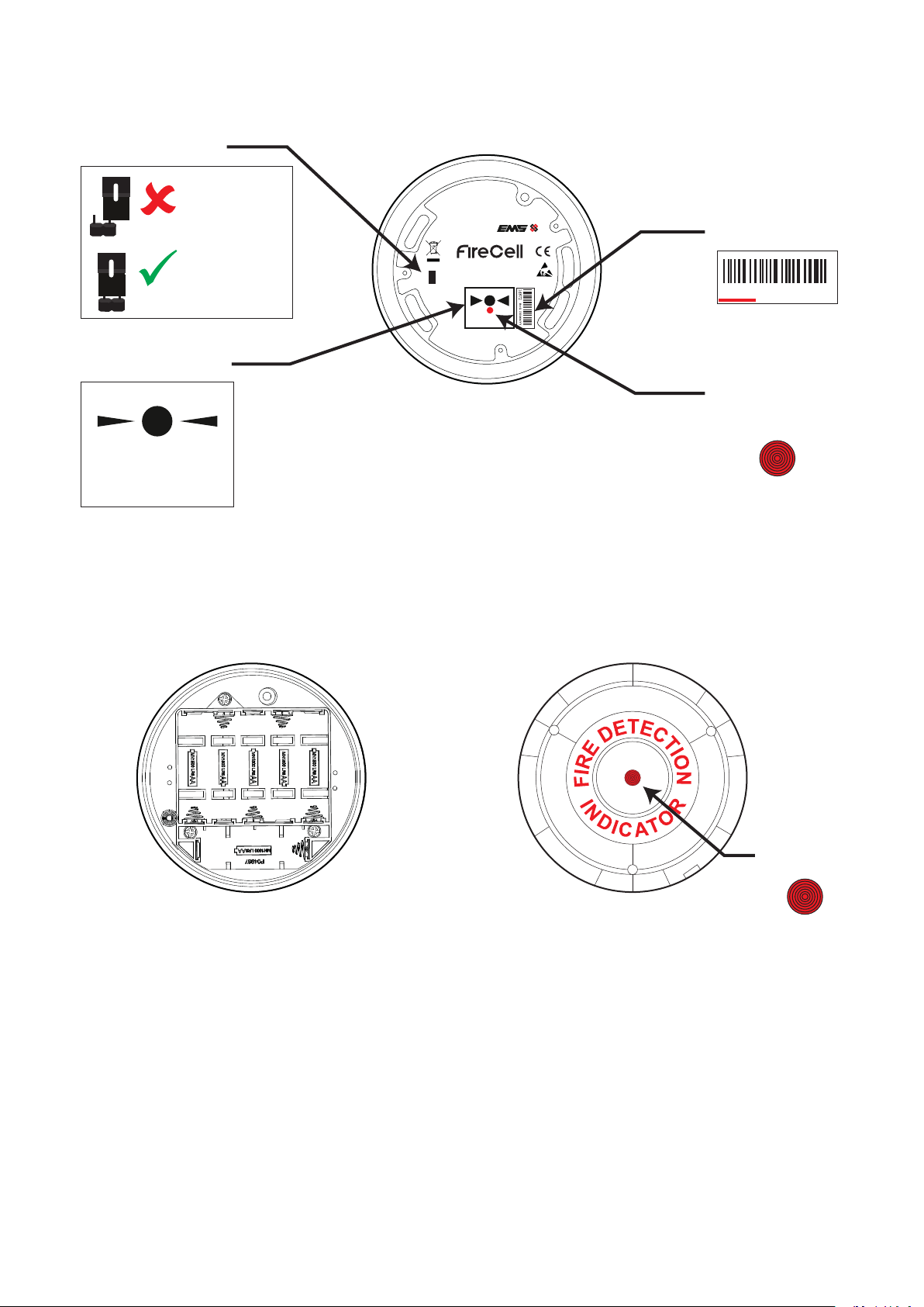
Wireless RIM familiarisation
Power jumper
unpowered
(pins unlinked)
device
powered
(both pins linked)
Log on button
PRESS HERE TO
LOG ON
device
Wireless Module
www.emsgroup.co.uk
Wireless Detector Base
Part No: FCZ-170-111
PRESS HERE TO
LOG ON
Ident number
RevX DD/MM/YY
1d872
Conrmation
LED
Battery compartment Remote Indicator
Fire LED
©2018 EMS Ltd. All rights reserved. Page 4 of 24 TSD115 Iss2 17/09/2018 AJM
Page 5
Adding a Wireless RIM to a Fusion Loop Module
Take the device to the Loop Module and follow the steps below:
With the loop module in its normal state, the screen will display:
Press the rotary control and the screen will display:
Turn the rotary control until the screen displays:
Press the rotary control and the screen will display:
Press the device’s log on button for 2 seconds (the device’s
DEV01 AL00 FT00
Device Status
Add New Device
Press Dev Log On
Add Dev xxxxx N?
conrmation LED will illuminate). The screen will display:
If the ident shown does not match the ident of the new device to be added, press the rotary
control (with the above Add Dev xxxxx N? display shown). This will return the display to the
previous menu.
If the device ident is correct, turn the rotary control until the
Add Dev xxxxx Y?
screen displays:
Press the rotary control and the screen will display:
Followed by:
Turn the rotary control, until the desired device address is shown:
Press the rotary control to conrm the device address. The screen
will display:
Press the BACK button, to return to the front display:
Adding
Address 002
Address 007
I/O Added
DEV02 AL00 FT00
©2018 EMS Ltd. All rights reserved. Page 5 of 24 TSD115 Iss2 17/09/2018 AJM
Page 6

Adding a Wireless RIM to a FireCell Radio Hub (manually)
Take the device to the Radio Hub and follow the steps below:
With the radio hub in its normal state the screen will display:
Press the rotary control and the screen will display:
Turn the rotary control until the screen displays:
Press the rotary control and the screen will display:
Turn the rotary control, until the screen displays the required
RCC to programmed the device to:
Press the rotary control and the screen will display:
Turn the rotary control until the screen displays the required
Loop to be programmed and press the rotary control to select.
DEV15 AL00 FT00
Device Status
Add New Device
RCC01=06 Max 31
RCC02=03 Max 31
Loop 1 Addr 016
Loop 2 Addr 007
Turn the rotary control until the screen displays the required
Add By Log On
addressis shown and press the rotary control to select. The
Press the rotary control and the screen will display:
Press Dev Log On
Press the device log on button for 2 seconds. The device’s
conrmation LED will illuminate and the she screen will display:
Add Dev xxxxx N?
If the ident shown does not match the ident of the new device to be added, press the rotary
control (with the above Add Dev xxxxx N? display shown). This will return the display to the
previous menu.
Conrm the ident number displayed is the same as located on the
device. If correct, turn the rotary control until the screen displays:
Add Dev xxxxx Y?
Press the rotary control and the screen will now conrm the new
devices loop and address number:
New Addr L2 A007
Press the BACK button until the screen displays:
Unassigned Dev
Press the rotary control and the screen will display:
©2018 EMS Ltd. All rights reserved. Page 6 of 24 TSD115 Iss2 17/09/2018 AJM
Device Status
Page 7

Turn the rotary control until the screen displays:
Assign Device
Press the rotary control and the screen will display:
Press the rotary control and the screen will display:
Followed by:
Assign ALL
Dev 000 of 001
Done 001 of 001
Note: If unsuccessful when operation is carried out next to the Radio Hub, re-try steps 16-19
with the device installed in its correct installed location.
Once complete, press the BACK button until the screen displays:
DEV16 AL00 FT00
©2018 EMS Ltd. All rights reserved. Page 7 of 24 TSD115 Iss2 17/09/2018 AJM
Page 8

Adding a Wireless RIM to a FireCell Radio Hub (via software)
When programming the Wireless RIM to a FireCell system via the conguration tool software, the
device should be added as an Input/Output unit.
All of the standard programming features for the device remain the same.
Details are explained below:
Add the Wireless RIM, by clicking on the ‘I/O Unit’ icon from the ‘Device Palette’.
The new device will be shown in the main window, allocated to the RCC as shown.
©2018 EMS Ltd. All rights reserved. Page 8 of 24 TSD115 Iss2 17/09/2018 AJM
Page 9

Complete the device’s ‘Ident’, ‘Loop’ and ‘Address’ elds shown below.
An example of an RCC programmed with three Wireless RIMs is shown below:
©2018 EMS Ltd. All rights reserved. Page 9 of 24 TSD115 Iss2 17/09/2018 AJM
Page 10

Adding a Wireless RIM to the Control Panel
The Wireless RIMs are added to the Loop Explorer conguration le as ‘Input/Output Wireless’
devices.
The selection of available wireless devices is shown below with the ‘Input/Output Wireless’ device
selected for the RIM highlighted.
Double click on the ‘Input/Output Wireless’ icon, shown above, to add the RIM to the setup. An
example is shown below:
Double click on the ‘Input/Output Unit Wireless’ icon shown above to expand the device to show
the input and output, as shown below:
©2018 EMS Ltd. All rights reserved. Page 10 of 24 TSD115 Iss2 17/09/2018 AJM
Page 11

Double click on the output eld. The display will change to show the device’s output properties.
Ensure all elds are un-selected and that a delay is not present.
Also ensure the zone setting for the output (Wireless RIM) corresponds with the zone that is to
cause the device to operate. An example with the correct settings to follow zone 1 operation is
shown below:
1
2
3
4
Note: the zone setting for the device (Wireless RIM) is only relevant for the cause and eect
when programming the unit to follow the activation of a zone of devices.
©2018 EMS Ltd. All rights reserved. Page 11 of 24 TSD115 Iss2 17/09/2018 AJM
Page 12

Linking a zone to a RIM
An example is shown below for linking a zone of devices to an individual RIM. In this example,
zone 1 is used.
Fire alarm in RIM allocated to
Zone 1
Zone 2
Zone 3, etc.
Click on the ‘Cause & Eect’ icon, shown below:
Zone 1
Zone 2
Zone 3, etc.
Double-click on the ‘Action’ icon, shown below:
©2018 EMS Ltd. All rights reserved. Page 12 of 24 TSD115 Iss2 17/09/2018 AJM
Page 13

The display will change to show available options for the input programming. Click on the ‘Fire
Zone Inputs’ icon and the display will now show individual zones. Click on the individual zone
required and the ‘OR/Single’ icon. An example below shows the settings required for zone 1.
1
2
Click the ‘Next >’ button once complete.
3
4
©2018 EMS Ltd. All rights reserved. Page 13 of 24 TSD115 Iss2 17/09/2018 AJM
Page 14

The display will change to show available options for the output programming.
Click on the ‘Fire Zone Outputs’ icon and the display will change to show individual zones.
Click on the required individual zone and select the ‘Continuous’ output type. An example below
shows the settings required for zone 1.
1
2
3
4
Click the ‘Next >’ button once complete.
5
©2018 EMS Ltd. All rights reserved. Page 14 of 24 TSD115 Iss2 17/09/2018 AJM
Page 15

The display will change and allow a text description to be allocated for the cause and eect rule
written. An example is shown below.
1
2
Enter the required text to identify the rule and click the ‘Finish’ button once complete.
The rules for the system will be displayed under the cause and eect icon on the Loop Explorer
front display. They will be individually identiable via the text description allocated. An example
is shown below.
Repeat the above programming for each of the Wireless RIMs on the system which are required to
follow individual zone activations.
©2018 EMS Ltd. All rights reserved. Page 15 of 24 TSD115 Iss2 17/09/2018 AJM
Page 16

Linking an individual device to a RIM
An example is shown below for linking an individual device to an individual RIM. In this example,
detection device 4 is associated with Wireless RIM device 6.
Fire detector address Associated RIM address
Device 1
Device 2
Device 3
Device 4
Device 5
Device 6
Click on the ‘Cause & Eect’ icon, as shown below:
Device 1
Device 2
Device 3
Device 4
Device 5
Device 6
Double-click on the ‘Action’ icon, shown below:
©2018 EMS Ltd. All rights reserved. Page 16 of 24 TSD115 Iss2 17/09/2018 AJM
Page 17

The display will change to show available options for the input programming.
Click on the individual device required (detector), followed by the ‘OR/Single’ action operator.
An example below shows the settings required for device 4.
2
1
Click the ‘Next >’ button once complete.
3
©2018 EMS Ltd. All rights reserved. Page 17 of 24 TSD115 Iss2 17/09/2018 AJM
Page 18

The display will change to show available options for the output programming.
Click on the individual device required (RIM), followed by the ‘Continuous’ output type.
An example below shows the settings required for remote indicator module device 6.
Click the ‘Next >’ button once complete.
1
3
2
©2018 EMS Ltd. All rights reserved. Page 18 of 24 TSD115 Iss2 17/09/2018 AJM
Page 19

The display will change and allow a text description to be allocated for the cause and eect rule
written. An example is shown below.
1
2
Enter the required text to identify the rule and click the ‘Finish’ button once completed.
The rules for the system will be displayed under the cause and eect icon on the Loop Explorer
front display. They will be individually identiable via the text description allocated. An example
is shown below.
Repeat the above programming for each of the Wireless RIMs on the system which are required
to follow individual device activations.
©2018 EMS Ltd. All rights reserved. Page 19 of 24 TSD115 Iss2 17/09/2018 AJM
Page 20

Testing RIM functionality
Once the programming of the Wireless RIMs is complete, it is recommended that their
functionality is fully tested to ensure correct operation.
Below are some testing recommendations to ensure correct functionality.
Cause & eect programmed for linking a zone of devices to a RIM.
Note: The RIM LED will only illuminate for re alarm activations in the associated Zone. The LED
should not illuminate for any other activations.
Activate a device into a re alarm condition, in a zone which also has a RIM allocated to that
zone.
Ensure that the device operated into an alarm condition’s LED illuminates, together with
the LED of the RIM associated with the zone.
Silence the control panel. The LEDs will still be illuminated.
Reset the re alarm condition on the control panel. The activated device and the associated
RIM’s LEDs will extinguish.
Repeat the above test for each device in the zone. On each occasion the RIM’s LED will
operate and follow the operation as described above.
Cause & eect programmed for linking an INDIVIDUAL DEVICE to a Remote Indicator
Module.
Activate a device into a re alarm condition which also has an associated Wireless RIM .
Ensure that the device operated into an alarm condition’s LED illuminates, together with
the LED of the device’s associated RIM.
Silence the Control panel. The LED’s will still be illuminated.
Reset the re alarm condition on the control panel. The activated device and the associated
RIM’s LEDs will extinguish.
Note: The RIM LED will only illuminate for Fire Alarm activations from the allocated device. The
LED should not illuminate for any other activations.
©2018 EMS Ltd. All rights reserved. Page 20 of 24 TSD115 Iss2 17/09/2018 AJM
Page 21

©2018 EMS Ltd. All rights reserved. Page 21 of 24 TSD115 Iss2 17/09/2018 AJM
Page 22

www.emsgroup.co.uk
+44 (0) 1227 369570
enquiries@emsgroup.co.uk
The information contained within this literature is correct at time of publishing. EMS reserves the right to change any information regarding products as part of its continual development
enhancing new technology and reliability. EMS advises that any product literature issue numbers are checked with its head oce prior to any formal specication being written.
©2018 EMS Ltd. All rights reserved. Page 22 of 24 TSD115 Iss2 17/09/2018 AJM
 Loading...