

Page 1
Installation Guide
TM
EkoMini
Repeater
Norcross, GA 30071 U. S. A.
900-1100-017 Rev. A
2850 Colonnades Court
+1.770.582.0555
Fax: +1.770.729.0075
Page 2

1.0 Unpacking:
Remove the EkoMiniTM repeater and the external power supply from the box. If an
EkoMini repeater kit was purchased, donor and server antennas should have been
received in separate shipping containers.
2.0 Additional Parts Needed for Installation:
Since every installation is different, other parts may need to be provided by the
installer:
• Donor antenna, unless an EkoMiniTM kit was purchased.
• Server antenna(s), unless an EkoMiniTM kit was purchased.
• 50 ohm Coaxial power splitter, if more than one server antenna is
needed.
• 50 ohm ½” flexible coaxial cable, plenum rated if required by building
code.
• Type N male connectors (or DIN 7-16, depending on the antenna
connector option)
• Mounting hardware for the donor antenna
• Weatherproofing compound
• Other miscellaneous installation items
3.0 Pre-setting the Configuration Switches:
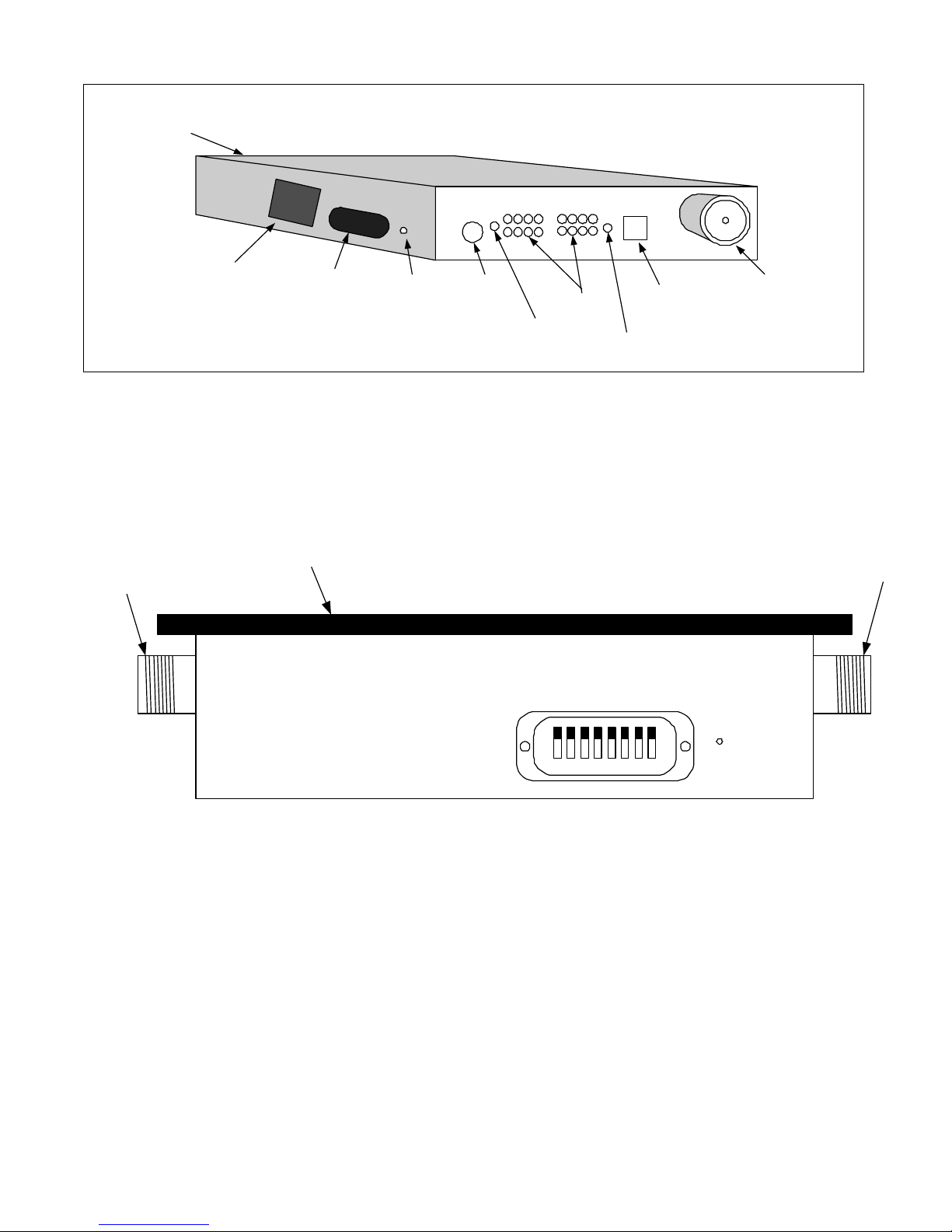
The EkoMiniTM is shown in Figure 1. It has a set of eight configuration “DIP” switches
located under a small removable panel. See Figure 2. For many installations, these
switches are set properly at the factory. However, they can be verified or changed
using this procedure:
• Remove the small switch panel with a Phillips head screwdriver.
• The switches are numbered 1 through 8, as shown in Figure 2
below. They can be turned “on” or “off” using a small screwdriver or
a bent paper clip. Note that each switch is “off” when it is pushed
“up” toward the repeater mounting flange.
• Position each of the eight switches as described below.
Page 3
Re-Rad (Server) Antenna
Port (rear panel)
Rerad Connector
Model
Number
Sticker
Configuration
Switch Removable
Panel
Reset
Button
DC Power
Connector
Power "ON" Indictor
(Green)
Signal
Level LEDs
Alarm Indicator (Red)
Figure 1: EkoMiniTM Repeater Illustration
Mounting Flange
Telephone
Connector
Donor
Antenna
Connector
Donor Connector
OFF
1 2 3 4 5 6 7 8
ON
Reset
Figure 2: EkoMiniTM Configuration Switches
3.1 Switches 1 and 2: Uplink Gain Offset
Pre-set these switches to “off”. After initial power on tests, these switches can be
adjusted if necessary. See Appendix A for full details.
Page 4

3.2 Switches 3 and 4: Bandpass Filter Position (800 MHz Models),
Band Selection (1900 MHz Models)
The function of these switches depends on the frequency band of operation. For
proper set-up, follow the guidelines in the chart below:
If Your Repeater Model is: Go to Section:
800 MHz Cellular A Band Series
(EkoMini 8-11-CA*-*)
800 MHz Cellular B Band Series
(EkoMini8-14CB*-*)
All other 800 MHz Models
(Cellular Full Band, SMR,
Public Safety Band, etc.)
EkoMini 1.9 – 15: 1900 MHz 15
MHz
EkoMini 1.9 – 5: 1900 MHz 5
MHz
3.2.1
3.2.2
Skip to Section 3.3
3.2.3
3.2.4
Page 5
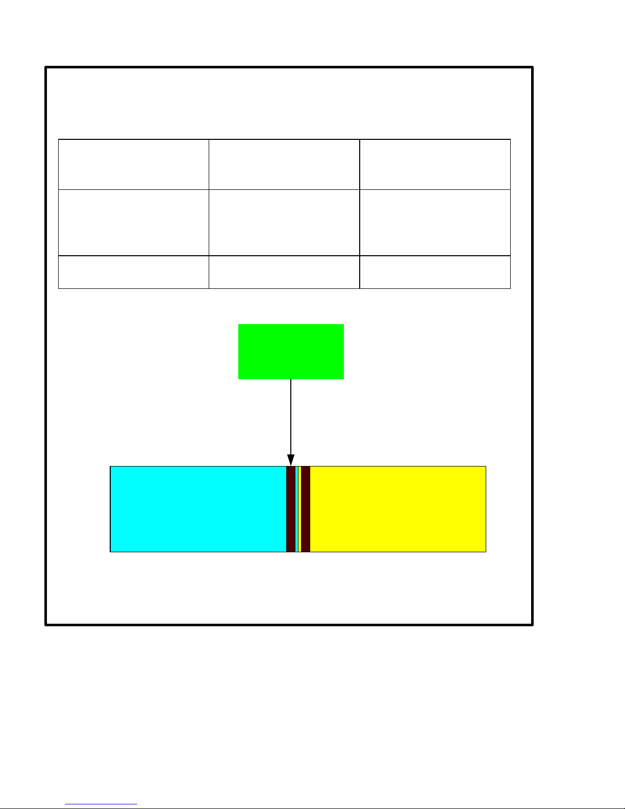
3.2.1 800 MHz Cellular A Band Series (EkoMini 8-11 CA*-*):
See Figure 3 below.
If the donor BTS
Switch 3 Position Switch 4 Position
uses control
channels:
In AMPS channel 317
On On
– 333 region (Zone 1)
(879.500 – 880.000
MHz)
Other area(s) of the A
Off Off
Band spectrum
Control Channel Zone 1:
879.500 - 880.000 MHz
AMPS Channel 317 - 333
Cellular Channel A (DL)
Figure 3: Control Channels in Zone 1 (879.500 – 880.000 MHz)
Cellular Channel B (DL)
Page 6
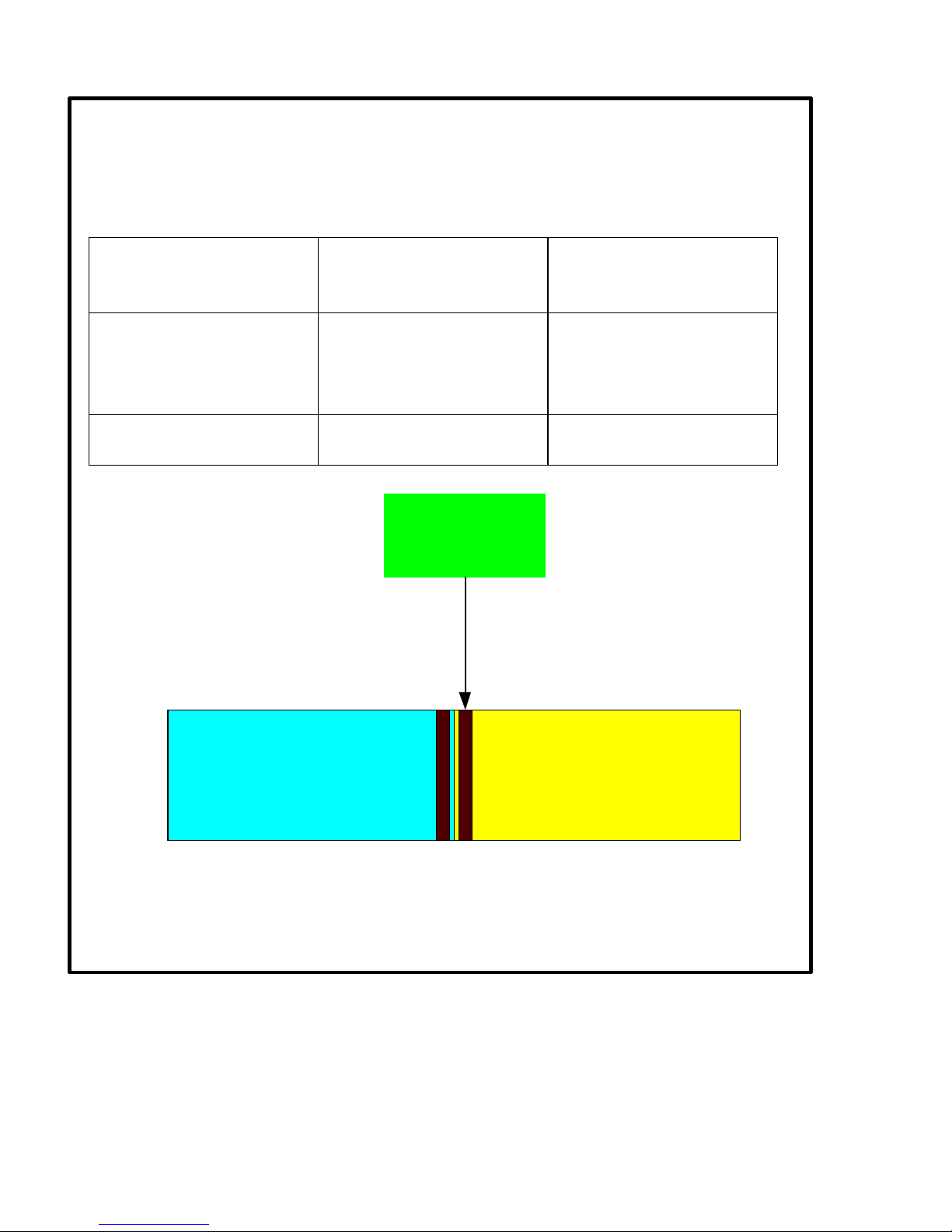
3.2.2 800 MHz Cellular B Band Series (EkoMini 8-14 CB*-*):
See Figure 4 below.
If the donor BTS
Switch 3 Position Switch 4 Position
uses control
channels:
In AMPS channel 334
On On
– 350 region (Zone 2)
(880.000 – 880.500
MHz)
Other area(s) of the B
Off Off
Band spectrum
Control Channel Zone 2:
880.000 - 880.500 MHz
AMPS Channel 334 - 350
Cellular Channel A (DL)
Figure 4: Control Channels in Zone 2 (880.000 – 880.500 MHz)
Cellular Channel B (DL)
Page 7

3.2.3 EkoMini 1.9
–
15: 1900 MHz
15
MHz Bandwidth (
Ba
nds A, B, or
C) Model:
To properly set the PCS band, see Table 2 below.
Band Selection Switch 3
Position
Switch 4 Position
A On On
B On Off
C Off On
Error – Fault indicated
by the DC LED indicator
flashing green.
Table 2: Switches 3 and 4 set-up for PCS 15 MHz models
Off Off
3.2.4 EkoMini 1.9 – 5: 1900 MHz 5 MHz Bandwidth (Bands D, E, or F)
Model:
To properly set the PCS band, see Table 3 below.
Band Selection Switch 3 Position Switch 4 Position
D On On
E On Off
F Off On
Error – Fault
Off Off
indicated by the DC
LED indicator
flashing green.
Table 3: Switches 3 and 4 set-up for PCS 5 MHz models
Page 8

3.3 Switch 5: CDMA Modulation
A different calibration table is needed for CDMA operation. Turn on switch 5 for
CDMA use.
Modulation Switch 5 Position
CDMA On
All other Off
3.4 Switch 6, 7, and 8: Downlink Peak Power Limit
For initial power-up, turn all these switches “off”. See Appendix B for full details.
This completes the configuration switch settings. Leave the cover off so adjustments
can be made later if needed.
4.0 Installing the EkoMiniTM:
Only qualified technicians should perform the installation. The user is cautioned that
modification or changes to this device not expressly approved by EMS Wireless
could void the user’s authority to operate this equipment.
The EkoMiniTM is designed for indoor use only. It should not be mounted outside.
• Determine the donor and server antenna(s) locations. Choose a
location for the EkoMiniTM that will minimize coaxial cable lengths to
these antennas, while maintaining adequate isolation. Also choose
a protected area such as an electrical or telephone room so the
EkoMiniTM will not be physically damaged. The location must also
be near a 100 - 240 VAC, 47 – 63 Hz outlet. See Figures 3 and 4
below – do not apply AC power without the coaxial cables and
antennas installed! If this is done, disconnect and then
reconnect the DC power cable after the antennas are
connected. This will initiate a software reset.
Page 9

Mounting Flange
Donor Connector
Reset
Rerad Connector
Figure 3: Do not apply power with the coaxial connectors disconnected!
Mounting Flange
Donor Connector
Reset
Rerad Connector
Figure 4: AC power OK – coaxial cables are connected
• Four mounting holes are provided to mount the EkoMiniTM to a wall
or ceiling. Allow access clearance to the small removable panel on
the side of the repeater near the model number sticker (for access
to the configuration switches), the reset button, the telephone
connector jack (if remote alarming will be used), and both coaxial
Page 10

connectors. Also, make sure you can see the front panel LED
indictors, as shown in Figure 1.
• Select a location for the external power supply, such as a protected
shelf, etc. Plug the power supply into the AC outlet, but do not plug
the power supply into the EkoMiniTM at this time. Only apply power
to the repeater after the donor and server antennas are installed
and connected.
5.0 Installing the Donor and Server antennas:
• Choose a donor antenna location that gives line-of-sight coverage
back to the donor base station, and install it according to the
manufacturer’s installation procedure.
• Install ½” flexible coaxial cable from the donor antenna to the
“Donor” port of the EkoMiniTM repeater.
• Install the server antenna per the antenna manufacturer’s
installation procedure.
• Install ½” flexible coaxial cable from the server antenna pigtail to the
“Rerad” port of the EkoMiniTM repeater.
• Most common installations will provide enough electrical isolation
between the donor and server antennas. In general, keep the donor
and server antennas separated by more than 75 feet. If there is any
question whether the isolation is adequate in a particular
installation, contact EMS Wireless Technical Support for
assistance.
6.0 Installing the Remote Alarming Telephone Cable (optional):
If the optional remote alarming is installed in the repeater, install a standard
telephone cable to the EkoMiniTM repeater using an RJ-11 connector. This should be
a dedicated telephone line. Remote alarming details are detailed in Appendix C.
7.0 Initial Power-up:
• Be sure the donor and server antennas and coax cables are
connected to the EkoMiniTM. Then, plug the power supply into the
AC outlet, and the DC power cord into the EkoMiniTM.
Page 11

• Allow several seconds for the EkoMiniTM automatic software
sequence to adjust the internal attenuators for proper operation.
• The EkoMiniTM should now be in proper operation. UL and DL
signal levels can be checked by watching the front panel LED
indicators. Each successive LED indicates 5 dB increase in signal
level, from –10 dBm to +20 dBm. If the signal is greater than +20
dBm, the “Overdrive” LED will light.
• Use a test phone to place a call. If there is excessive noise in the
uplink BTS receiver when using the repeater, see Appendix A to
reduce the UL gain of the repeater.
• If you want to manua lly reduce the repeater DL power output (i.e. to
deliberately limit coverage area, etc.), see Appendix B.
• For remote log-in procedures using a computer, see Appendix C.
Complete details are found in the Operator’s Manual.
Note: If any of the DIP configuration switches are changed after the repeater is
turned on, the unit must be reset for the new switch configuration to take
effect. This is done by using a bent paperclip. Press and hold the reset button
until the front panel LEDs “flash” (generally a few seconds). Release the
switch and allow the unit to re-start. Alternatively, the DC power cable can be
unplugged from the repeater and then plugged in again. This will initiate a
reset sequence.
8.0 Troubleshooting
The EkoMini
set-up conditions or resetting the unit. Other problems require repair of the unit at
EMS Wireless.
Whenever an unexpected operating condition is encountered, the unit should be reset
using the following two step procedure:
• Step 1 – “Soft Reset”: Be sure that power is applied to the repeater
TM
has no field replaceable parts. Repair is limited to correcting improper
using the provided power supply. Using a bent paper clip, press and
hold the reset button found in the small hole in the repeater housing
(see Figure 3 to locate this hole). Watch for the front panel LED
indicators to “flash” after a few seconds, and then release the reset
Page 12

button. Normal operation should occur. If it does not, perform a “hard
reset” described in step 2.
• Step 2 – “Hard Reset”: Again using a bent paperclip, press and hold
the reset button. While the button is held down, remove the DC power
cable from the repeater, and then plug the cable back in. Continue to
hold the reset button for approximately 45 seconds, and then release
it. This procedure completely resets the repeater’s microprocessor
and other software settings. Normal operation should occur. Note: If
the remote alarming option is installed, this “hard reset” will reset all
user names and passwords back to the factory default settings
described in the Operator’s Manual.
Other troubleshooting procedures are described in the table below.
Problem Probable Cause Corrective Action
No Power (Green
power LED is off)
Power Supply
problem
Reconnect power
supply to repeater.
Verify AC power
source; plug in power
supply if necessary.
Alarm Light is On No Downlink Signal Check downlink
signal level with a
spectrum analyzer.
Check band switches
3 and 4 on PCS
models.
Low Downlink Signal,
possibly with alarm
issued
Donor antenna is
mis-aligned, DL cable
is faulty, BTS is not
line of sight, BTS is
excessively far from
repeater site, etc.
Measure downlink
signal level with a
spectrum analyzer.
Improve DL signal by
raising the donor
antenna, re-orienting
the donor antenna,
re-orienting unit to
shorten cable runs,
etc.
Uplink –10 dBm
signal level is on
Normal condition if no
mobile phones are in
use near the repeater
Activate a mobile
phone and move it
close to the server
antenna. UL signal
Page 13

Unit issues alarm and
shuts down after 5
minutes
Flashing green Power
LED
Unable to log in with
HyperTerminal, etc.
Excessive DL or UL
signal is overdriving
repeater
Configuration
switches 3 and 4 are
both turned “off” on
PCS models.
Remote alarm option
not installed.
level should increase.
Lower signal levels
by moving phone
away from server
antenna, etc.
Toggle switches to
correct frequency
band; then reset unit.
Check unit model
number – “N”
indicates remote
alarming is not
installed.
Page 14

Appendix A: Manually Reducing the Uplink Gain
If excessive noise is received in the BTS uplink receiver during repeater use, the
repeater uplink signal may be too strong. Up to 6 dB attenuation of the repeater UL
signal may be inserted by toggling switches 1 and 2 according to the table below.
Note: This manual control overrides the automatic set-up software. It also
unbalances the UL gain relative to the DL gain.
UL Gain Offset
Relative to DL
0 dB Off Off
-2 dB On Off
-4 dB Off On
-6 dB On On
Be sure to press the “reset” button to make these changes effective.
Switch 1 Position Switch 2 Position
Page 15

Appendix B: Manually Reducing the Downlink Power Output Limit:
The downlink peak power output limit may be manually controlled over a 14 dB range
using switches 6, 7, and 8. Note: This manual control overrides the automatic set-up
software.
DL Peak Power
Switch 6
Position
Switch 7
Position
Switch 8
Position
Limit (dBm)
+20 Off Off Off
+18 On Off Off
+16 Off On Off
+14 On On Off
+12 Off Off On
+10 On Off On
+8 Off On On
+6 On On On
Be sure to press the “reset” button to make these changes effective.
Page 16

Appendix C: Summary of Remote Log-in Procedure:
Repeater Serial
Number
System Date
and Time
Software
Version #
DL and UL RF
Power Output
Levels, dBm
DL RF Peak
Output Level, dBm
UL RF Offset Relative
• Connect the EkoMiniTM repeater to a telephone line using the front
panel RJ-11 connector.
• Connect a computer (laptop preferred) with a modem to a telephone
line. Configure a HyperTerminal session for 2400, 8, 1, None,
None.
• Dial the appropriate telephone number. The repeater should
answer after approximately two rings.
• Press the ENTER key. The prompt “Password?” will appear. Enter
the default password of ‘11111’ followed by the ‘Enter’ key.
• After a few seconds, the following screen should appear, shown in
Figure C-1 below.
to DL, dB
Alarm Condition
Figure C-1: EkoMiniTM Remote Login Session
Page 17

This screen can be used to see most of the important repeater details, and to
diagnose performance problems, if needed. It should be noted that the power
sensors in the repeater cannot register an accurate level at less than –10 dBm. If –
10 dBm is listed for any parameter, it is likely the level is lower than that. In the case
of Figure C-1 above, the DL RF output is shown as –10 dBm because no downlink
signal was connected.
Complete details of the available remote software commands are shown in the
Operator’s Manual.
 Loading...