

Page 1

FCC Part 22
Transmitter Certification
Test Report
FCC ID: DNY0A5EPCELL20REM
FCC Rule Part: CFR 47 Part 22 Subpart H
ACS Report Number: 06-0471-22H
Manufacturer: EMS Wireless
Equipment Type: Cellular Fiber Optic DAS
Tradename: EkoLink Plus
Model: EPCELL20REM
®
II
Manual
5015 B.U. Bowman Drive Buford, GA 30518 USA Voice: 770-831-8048 Fax: 770-831-8598
Page 2
Operator’s Manual
®
EkoLink Plus
Fiber Optic Distributed Antenna System
900-5000-017 REV. B
2850 Colonnades Court
Norcross, GA 30071
770.582.0555
Fax 770.729.0075
Page 3

EMS Wireless Operator’s Manual
EkoLink Plus Fiber Optic DAS
Disclaimer
Every attempt has been made to make this material complete, accurate, and up-todate. Users are cautioned, however, that EMS Wireless reserves the right to make
changes without notice and shall not be responsible for any damages, including
consequential, caused by reliance on the material presented, including, but not
limited to, typographical, arithmetical, or listing errors.
Copyright Information
© 2001 by EMS Wireless
EMS Wireless
Norcross, GA
2
Page 4

EMS Wireless Operator’s Manual
EkoLink Plus Fiber Optic DAS
WARNINGS, CAUTIONS, AND GENERAL NOTES
This product conforms to FCC Part 15, Section 21. Changes or modifications not
expressly approved by the party responsible for compliance could void the user's
authority to operate the equipment. .
NOTE: This equipment has been tested and found to comply with the limits for a
Class B digital device, pursuant to Part 15 of the FCC Rules. These limits are
designed to provide reasonable protection against harmful interference in a
residential installation. This equipment generates, uses, and can radiate radio
frequency energy and, if not installed and used in accordance with the
instructions, may cause harmful interference to radio communications. However,
there is no guarantee that interference will not occur in a particular installation. If
this equipment does cause harmful interference to radio or television reception,
which can be determined by turning the equipment off and on, the user is
encouraged to try to correct the interference by one or more of the following
measures:
• Reorient or relocate the receiving antenna.
• Increase the separation between the equipment and receiver.
• Connect the equipment into an outlet on a circuit different from that to
which the receiver is connected.
• Consult the dealer or an experienced radio/TV technician for help.
This Class B digital apparatus meets all requirements of the Canadian Interference
Causing Equipment Regulations. Operation is subject to the following two
conditions: (1) this device may not cause harmful
interference, and (2) this device must accept any interference received, including
interference that may cause undesired operation.
Cet appareillage numérique de la classe B répond à toutes les exigences de
l'interférence canadienne causant des règlements d'équipement.L'opération est
sujette aux deux conditions suivantes: (1) ce dispositif peut ne pas causer
l'interférence nocive, et (2) ce dispositif doit accepter n'importe quelle interférence
reçue, y compris l'interférence qui peut causer l'opération peu désirée.
Installation should be made per ANSI/NFPA 70, the National Electrical Code(NEC),
Article 810 specifically for clearances from power and lighting conductors,
mounting and grounding.
3
Page 5

EMS Wireless Operator’s Manual
EkoLink Plus Fiber Optic DAS
The screen of the coax cable must be connected to earth(grounded) at the
entrance to the building. This should be done in accordance with applicable
National Electrical Code(NEC) installation codes. In the U.S., this is required by
Section 820.93 of the National Electrical Code, ANSI/NFPA 70.
IC Requirements
` The Manufacturer's rated output power of this equipment is for single carrier
operation. For situations when multiple carrier signals are present, the rating
would have to be reduced by 3.5 dB, especially where the output signal is
re-radiated and can cause interference to adjacent band users. This power
reduction is to be by means of input power or gain reduction and not by an
attenuator at the output of the device.
Safety Considerations
When installing or using this product, observe all safety precautions during
handling and operation. Failure to comply with the following general safety
precautions and with specific precautions described elsewhere in this
manual violates the safety standards of the design, manufacture, and
intended use of this product. EMS Wireless assumes no liability for the
customer's failure to comply with these precautions.
WARNING
WARNING Calls attention to a procedure or practice, which, if ignored, may result
in damage to the system or system component. Do not perform any procedure
preceded by a WARNING until described conditions are fully understood and met.
If You Need Help
If you need additional copies of this manual, or have questions about
system options, or need help with installation and using of the system,
please contact EMS Wireless’ Customer Support Department.
2850 Colonnades Court
Norcross, GA 30071 USA
770.582.0555 ext. 5310
cswireless@ems-t.com
4
Page 6

EMS Wireless Operator’s Manual
EkoLink Plus Fiber Optic DAS
Service
Do not attempt to modify or service any part of this product other than in
accordance with procedures outlined in this Operator's Manual. If the
product does not meet its warranted specifications, or if a problem is
encountered that requires service, notify EMS Wireless’ Customer Support
department. Service will be rendered according the EMS Wireless’ warranty
and repair policy. The product shall not be returned without contacting EMS
Wireless and obtaining a return authorization number from the Customer
Service department
When returning a product for service, include the following information:
Owner, Model Number, Serial Number, Return Authorization Number
(obtained in advance from EMS Wireless Customer Service Department),
service required and/or a description of the problem encountered.
Warranty and Repair Policy
The EMS Wireless Quality Plan includes product test and inspection
operations to verify the quality and reliability of our products.
EMS Wireless uses every reasonable precaution to ensure that every device
meets published electrical, optical, and mechanical specifications prior to
shipment. Customers are asked to advise their incoming inspection,
assembly, and test personnel as to the precautions required in handling and
testing ESD sensitive opto-electronic components. Physical damage to the
external surfaces voids warranty.
These products are covered by the following warranties:
1. General Warranty
EMS Wireless warrants to the original purchaser all standard products
sold by EMS Wireless to be free of defects in material and
workmanship for the duration of the warranty period of two (2) years
from date of shipment from EMS Wireless. During the warrant y period,
EMS Wireless’ obligation is limited to repair or replacement of any
product that EMS Wireless proves to be defective. This warranty does
not apply to any product, which has been subject to alteration, abuse,
improper installation or application, accident, electrical or
environmental over-stress, negligence in use, storage, transportation
or handling.
5
Page 7

EMS Wireless Operator’s Manual
EkoLink Plus Fiber Optic DAS
2. Specific Product Warranty Instructions
All EMS Wireless products are manufactured to high quality standards
and are warranted against defects in workmanship, materials and
construction, and to no further extent. Any claim for repair or
replacement of a device found to be defective on incoming inspection
by a customer must be made within 30 days of receipt of the shipment,
or within 30 days of discovery of a defect within the warranty period.
This warranty is the only warranty made by EMS Wireless and is in lieu
of all other warranties, expressed or implied, except as to title, and can
be amended only by a written instrument signed by an officer of EMS
Wireless. EMS Wireless Customer Support agents or representatives
are not authorized to make commitments on warranty returns.
In the event that it is necessary to return any product against the
above warranty, the following procedure shall be followed:
a. Return authorization shall be received from EMS Wireless
Customer Support prior to returning any device. Advise EMS
Wireless Customer Support of the model, serial number, and the
discrepancy. The device shall then be forwarded to EMS
Wireless, transportation prepaid. Devices returned freight collect
or without authorization may not be accepted.
b. Prior to repair, EMS Wireless Customer Support will advise the
customer of EMS Wireless test results and will advise the
customer of any charges for repair (usually for customer caused
problems or out-of-warranty conditions).
If returned devices meet full specifications and do not require
repair, or if the customer does not authorize non-warranty
repairs, the device may be subject to a standard evaluation
charge. Customer approval for the repair and any associated
costs will be the authority to begin the repair at EMS Wireless.
Customer approval is also necessary for any removal of certain
parts, such as connectors, which may be necessary for EMS
Wireless testing or repair.
c. Repaired products are warranted for the balance of the original
warranty period, or at least 90 days from date of shipment.
6
Page 8

EMS Wireless Operator’s Manual
EkoLink Plus Fiber Optic DAS
3. Limitations of Liabilities
EMS Wireless’ liability on any claim of any kind, including negligence,
for any loss or damage arising from, connected with, or resulting from
the purchase order, contract, or quotation, or from the performance or
breach thereof, or from the design, manufacture, sale, delivery,
installation, inspection, operation or use of any equipment covered by
or furnished under this contract, shall in no case exceed the purchase
price of the device which gives rise to the claim.
EXCEPT AS EXPRESSLY PROVIDED HEREIN, EMS WIRELESS MAKES
NO WARRANTY OF ANY KIND, EXPRESSED OR IMPLIED, WITH
RESPECT TO ANY GOODS, PARTS AND SERVICES PROVIDED IN
CONNECTION WITH THIS AGREEMENT INCLUDING, BUT NOT
LIMITED TO, THE IMPLIED WARRANTIES OF MERCHANTABILITY AND
FITNESS FOR A PARTICULAR PURPOSE. EMS WIRELESS SHALL
NOT BE LIABLE FOR ANY OTHER DAMAGE INCLUDING, BUT NOT
LIMITED TO, INDIRECT, SPECIAL OR CONSEQUENTIAL DAMAGES
ARISING OUT OF OR IN CONNECTION WITH FURNISHING OF GOODS,
PARTS AND SERVICE HEREUNDER, OR THE PERFORMANCE, USE
OF, OR INABILITY TO USE THE GOODS, PARTS AND SERVICE.
EMS Wireless test reports or data indicating mean-time-to-failure,
mean-time-between-failure, or other reliability data are design guides
and are not intended to imply that individual products or samples of
products will achieve the same results. These numbers are to be used
as management and engineering tools, and are not necessarily
indicative of expected field operation. These numbers assume a
mature design, good parts, and no degradation of reliability due to
manufacturing procedures and processes.
This fiber optic laser transmitter contains a class IIIb laser product as defined
by the US Department of Health and Human Services, Public Health Service,
Food and Drug Administration. This laser product complies with 21 CFR,
Chapter I, Subchapter J of the DHEW standards under the Radiation Control
for Health and Safety Act of 1968. The laser module certification label is
located on the equipment enclosure and it also shows the required DANGER
warning logotype (as shown below).
7
Page 9

EMS Wireless Operator’s Manual
R
EkoLink Plus Fiber Optic DAS
The EMS Wireless laser products are used in optical fiber communications
systems for radio frequency and microwave frequency analog fiber optic
links. In normal operation, these systems are fully enclosed and fully
shielded by the hermetically sealed laser metal package. Laser bias current
is limited by the internal control circuitry. The transmitters are coupled to
glass fiber and have 1310/1550 nm optical output wavelength with typically
0.5 to 20 mW output depending on the model. The optical radiation is
confined to the fiber core. Under these conditions, there is no accessible
laser emission and hence no hazard to safety or health.
Since there is no human access to the laser output during system operation,
no special operator precautions are necessary when fiber is connected to the
transmitter and receiver. During installation, service, or maintenance, the
service technician is warned, however, to take precautions, which
include not looking directly into the fiber connector or the fiber that is
connected to the fiber connector before it is connected to the fiber
optic receiver. The light emitted from the fiber optic connector or any
fiber connected to the connector is invisible and may be harmful to the
human eye. Use either an optical power meter or an infrared viewer or
fluorescent screen for optical output verification. All handling
precautions as outlined by the FDA and ANSI Z136.2 and other
authorities of class IIIb lasers must be observed.
Do not attempt to modify or to service this Product. Contact the EMS
Wireless Customer Support Department for a return authorization if service
or repair is necessary.
8
DANGER
INVISIBLE LASER RADIATION
A VOID DIRECT EXPOSURE TO BEAM
PEAK POWER 30 mW
WAVELENGTH 1300/1550 nm
CLASS IIIb LASER PRODUCT
THIS PRODUCT COMPLIES WITH 21 CF
CHAPTER I SUBCHAPTER J
Page 10

EMS Wireless Operator’s Manual
EkoLink Plus Fiber Optic DAS
Handling the EkoLink Plus
1. Use ESD (electrostatic discharge) precautions when dealing with the modules
within the EkoLink Plus so that units are not damaged.
2. Opening any module voids the wa rranty .
3. Modules cannot be "hot-swapped" (removed while unit is in operation).
Disconnecting any component within the EkoLink Plus when powered can
damage or destroy the equipment and will void the warranty. Unit must not be
operating when modules are removed for replacement.
9
Page 11

EMS Wireless Operator’s Manual
EkoLink Plus Fiber Optic DAS
TABLE OF CONTENTS
1.0 General Information
2.0 Equipment Mounting and Installation
2.1 Hub Mounting
2.2 Remote Mounting
2.3 Cabling
3.0 System Set-up and Turn-on
3.1 Automatic Set-up
3.1.1 Hub Set-up
3.1.2 Remote Set-up
3.2 Manual System Set-up
4.0 System Optimization
5.0 Major Modular Components – Technical Description
5.1 Remote Unit
5.1.1 Channelizer Modules
5.1.2 Power Amplifier
5.1.3 Power Supply Module
5.1.4 Duplex Filter
5.1.5 Status and Control Module
5.1.6 Interconnect Module
5.1.7 Fiber Optic Transceiver
5.2 Hub Unt
5.2.1 Hub Interface Module
5.2.2 Fiber Optic Transceiver
5.2.3 Hub Control Module
5.2.4 Hub Power Supply Module (Optional)
6.0 EkoLink Plus Specifications
6.1 EkoLink Plus RF Specifications
6.2 EkoLink Plus Mechanical Specifications – Remote
6.3 EkoLink Plus Mechanical Specifications – Hub
6.4 EkoLink Plus Environmental Specifications
7.0 Detailed Software Commands
7.1 General
7.2 Software Command Set
7.3 Communication via the MirrorCell Unit Manager
Appendix A: Installing the Wireless Modem into an EkoLink Plus
Appendix B: HyperTerminal Configuration
10
Page 12

EMS Wireless Operator’s Manual
EkoLink Plus Fiber Optic DAS
TABLE OF FIGURES
Figure 1: Mechanical Diagram of the EkoLink Plus Hub, Rack Mount
Configuration
Figure 2: Mechanical Diagram of the EkoLink Plus Hub, Waterproof Housing
Configuration
Figure 3: Mechanical Diagram of EkoLink Plus Remote Unit
Figure 4: Rack Mounted EkoLink Plus Hub
Figure 5: Wall Mounted EkoLink Plus Hub
Figure 6: Wall Mounted Remote Unit
Figure 7: Remote Unit with Optional Battery Back-up Unit
Figure 8: EkoLink Plus Cabling Connections
Figure 9: Remote Unit Connections
Figure 10: Neighbor List Changes
Figure 11: General Block Diagram of EkoLink Plus System
Figure 12: Block Diagram of EkoLink Plus Hub
Figure 13: EkoLink Plus Remote Unit Block Diagram
Figure B-1: Connection Description in HyperTerminal
Figure B-2: HyperTerminal Screen for Direct Connection
Figure B-3: HyperTerminal Screen for Mod em Co nn ection
Figure B-4: Port Settings for Direct Connection and Remote Connection
11
Page 13

EMS Wireless Operator’s Manual
EkoLink Plus Fiber Optic DAS
LIST OF TABLES
Table 1: Default User Names and Passwords
Table 2: EkoLink Plus RF Specifications
Table 3: EkoLink Plus Remote Mechanical Specifications
Table 4: EkoLink Plus Hub Mechanical Specifications
Table 5: EkoLink Plus Environmental Specifications
Table 6: Manual Software Command List
12
Page 14

EMS Wireless Operator’s Manual
EkoLink Plus Fiber Optic DAS
1.0 GENERAL INFORMATION
The EkoLink Plus Fiber Optic Distributed Antenna System (DAS), provides excellent
signal coverage of most all large buildings, multiple buildings, airports, convention
centers as well as large outdoor environments such as university campuses, rural
stretches of highway, etc. With the correct selection of equipment, this can include a
combination of outdoor and in-building coverage for multi-building office parks, etc.
The EkoLink Plus System offers these general features:
• Remote alarming through the hub unit. This allows technicians to monitor
system performance remotely via telephone line and computer with modem and
terminal software.
• Truly “plug and play” operation, with a totally automatic software set-up
sequence, in the hub and all remote units, or manual control capability for
specific setups.
• Remote units have true automatic gain control to allow compensation for RF
source variations, optical loss, or other variations in power level.
• The monitoring and control of the system occurs with a direct connection to a
laptop computer, wireless modem, or via a wireline option for remote access.
• The system uses single mode fiber optic cable to connect the hub to the
remote(s). This eliminates the large signal losses inherent in long runs of coax or
CAT 5 (twisted pair) cables used in other systems. For this reason, very long (up
to five kilometers) fiber optic cables can be used to provide coverage very far
away from the hub unit in large complexes of buildings or large outdoor areas.
• The unit operates with +20 dBm RF donor signal level, which is conveniently
obtained via direct coaxial cable launch from a BTS with appropriate attenuators.
The advantage of using a dedicated micro BTS for the DAS is dramatically
increased system capacity within the covered building. The BTS interface is a
pair of coaxial connections to independent receive and transmit ports. Optionally
an interface is available to connect to a duplexed BTS output.
• The Eko Link Plus is a band selective Fiber Optic Distributed Antenna System
(DAS), designed to be fully compliant with GSM-AMPS-TDMA-CDMA standards.
• Standard downlink path output power is 2 watts (+33 dBm), 4 watts (+36 dBm), 8
watt (+39 dBm) or 20 watt (+43 dBm) composite. The uplink path provides an
approximate 3 dB system overall gain.
• The EkoLink Plus can be optionally configured with two independent passbands
for each radio frequency path. This means that two PCS bands can be covered
13
Page 15

EMS Wireless Operator’s Manual
EkoLink Plus Fiber Optic DAS
with one system. At Cellular 800 MHz, A + A’ + A” or B + B’ extended band
segments can be covered with one unit.
• The EkoLink Plus system will support up to four remotes per hub or two remotes
with the diversity receive option. Diversity receive is accomplished by processing
an additional receive signal (using a second receive antenna) at a particular
remote unit. This signal is sent via fiber optic cable back to the hub unit. This
allows for spatial or polarization diversity to be supported, similar to a BTS.
• Optionally, Wave Division Multiplexing (WDM) can be added to the system,
allowing for a single fiber optic cable from the hub to each remote, which handles
both uplink and downlink signals.
• An optional wireless or wireline modem can be equipped at the remotes and or at
the hub location. The modem allows for remote alarm and control of the units via
MUM software or a laptop computer.
More specific technical features can be found in the Technical Specifications and the
Technical Description sections of this Operator’s Manual.
Figure 1 shows a mechanical diagram of the Hub in the rack mount configuration.
Figure 2 shows the hub in the optional waterproof housing, and Figure 3 shows the
remote unit.
14
Page 16

EMS Wireless Operator’s Manual
EkoLink Plus Fiber Optic DAS
17.52
( 445mm )
14.08
( 358mm )
4.000
2x
( 102mm )
.278
4x
4x
(7.1mm )
.406
( 10.3mm )
OPTICS
OPTICS
OPTICS
Output
Output
Output
Laser
Laser
Laser
DC
DC
DC
Optical Rx
Optical Rx
Optical Rx
Input
Input
Input
19.00
( 483mm )
RS232/SERIAL
1.9 GHZ
RX
TX
800 MHZ
RX
TX
MODEM
ALARM OUTPUT
DC INPUT
A Division of EMS Technologies, Inc.
OPTICS
Output
Laser
DC
Optical Rx
Input
18.31
( 465mm )
A Division of EMS Technologies, Inc.
EKO-LINK PLUS
6.968
( 177mm )
6.91
(175)
Figure 1: Mechanical Diagram of the EkoLink Plus Hub, Rack Mount
Configuration
15
Page 17

EMS Wireless Operator’s Manual
EkoLink Plus Fiber Optic DAS
7.9
(200mm)
8.2
(207mm)
Figure 2: Simplified EkoLink Plus Hub Block Diagram
21.25
2x
(540mm)
.406
4x THRU
O
(10mm)
14.25
2x
(362mm)
15.7
400mm
19.7
(500mm)
Figure 2: Mechanical Diagram of the EkoLink Plus Hub, Waterproof Housing
Configuration
16
Page 18

EMS Wireless Operator’s Manual
EkoLink Plus Fiber Optic DAS
(.95)
15.25
( 387m m )
11.75
( 298 mm )
14.22
(361mm)
.406
O
4x
(10mm)
11.75
(298mm)
10.90
2x
(277mm)
( 461m m )
23.12
(587mm)
18.16
2x
(394mm )
15.50
19.03
( 483m m )
1.28
(4.01)
AIR FLOW
DIRECT ION
FAN ENCLOSURE
2x
(33mm)
Figure 3: Mechanical Diagram of EkoLink Plus Remote Unit
17
Page 19

Page 20

EMS Wireless Operator’s Manual
EkoLink Plus Fiber Optic DAS
2.0 Equipment Mounting and Installation
The following general recommendations should be adhered to for optimal performance.
1. The remote units should be mounted so the heatsink avoids direct sunlight. This
will extend the life of these units.
2. The remote units must be mounted upright so that the connectors are on the
underside. This will help prevent a buildup of moisture inside the cabinet.
3. The hub and remotes are equipped with N-type antenna connectors. Connectors
are located on the bottom of the remote cabinet.
4. Ensure that adequate room has been allocated for the bending radius of the
cables. Refer to the cable manufacturer’s specifications for the allowable cable-bend
radius.
5. Ensure that adequate room is allowed for the opening and closing of the
remote unit door. See the specification table for dimensions of the cabinet.
2.1 Hub Mounting
The hub should be mounted as close as possible to the donor BTS. The 19” (48.3 cm)
rack mount version is shown in Figure 4. The alternate NEMA 4 weatherproof wall
mounted enclosure is shown in Figure 5. Observe all environmental specifications for
the hub to avoid damage from moisture, heat, cold, etc.
19
Page 21

EMS Wireless Operator’s Manual
EkoLink Plus Fiber Optic DAS
Figure 4: Rack Mounted EkoLink
Plus Hub
Figure 5: Wall mounted
EkoLink Plus Hub
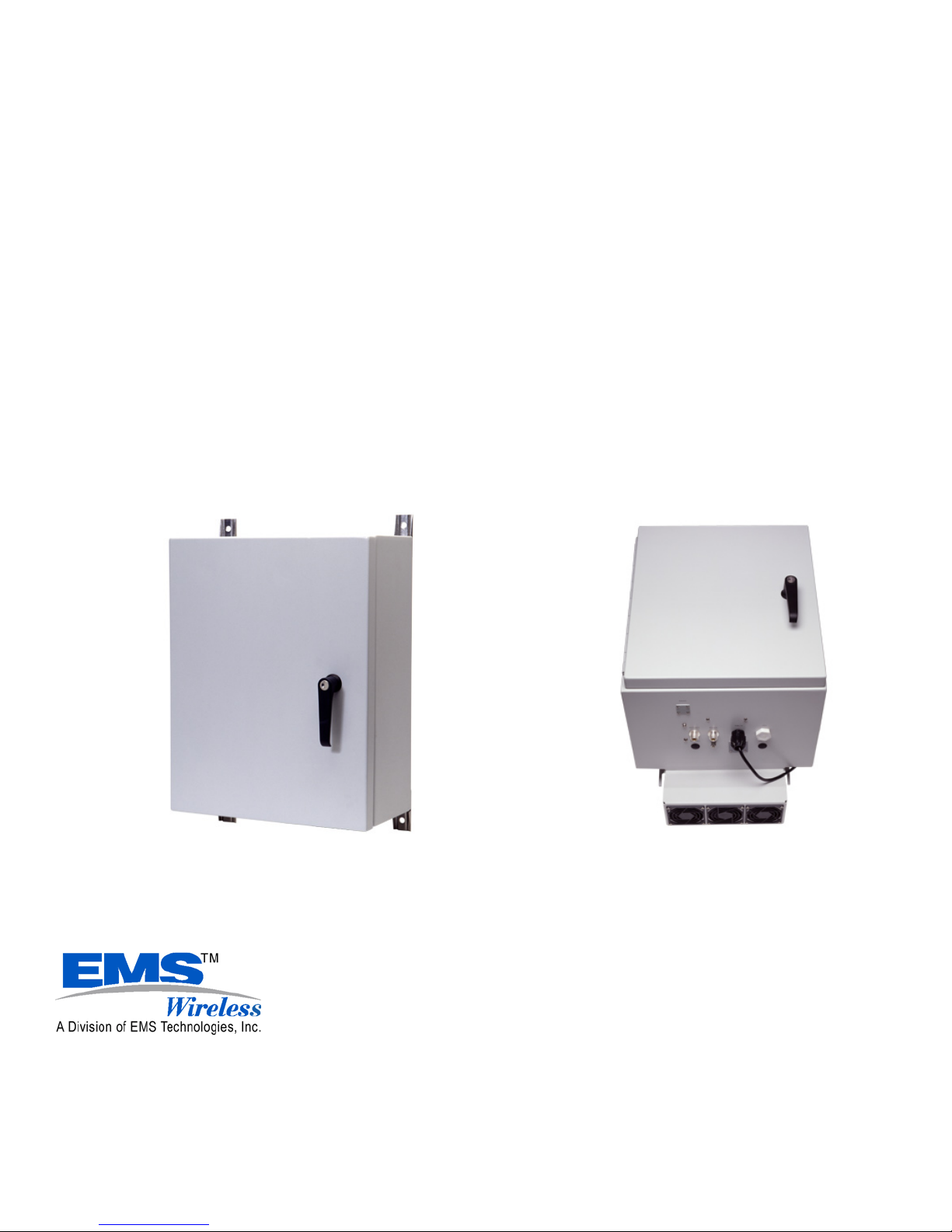
2.2 Remote Mounting
Ensure that each remote location is as close as possible to the antenna(s) it serves.
Observe all environmental specifications for the remote to avoid damage from
moisture, heat, cold, etc.
An example of the wall mounted remote is shown in Figure 6. A battery back-up unit
may be included as part of the system. This unit should be mounted close to the
EkoLink Plus remote, as shown in Figure 7.
Pole mounting is another popular method of mounting the remote. U-bolts and
“unistrut” stock may be used to easily mount the remote.
20
Page 22

EMS Wireless Operator’s Manual
EkoLink Plus Fiber Optic DAS
Figure 7: Remote Unit with optional
Battery Back-up Unit
Figure 6: Wall mounted remote unit
2.3 Cabling
A cabling schematic showing the hub connections is shown in Figure 8. The remote
connections are shown in Figure 9.
21
Page 23

EMS Wireless Operator’s Manual
EkoLink Plus Fiber Optic DAS
EkoLink Plus Hub Connections
(Configured without WDM, and without
Receive Diversity)
Remote 1 Downlink
Single Mode Fiber
Optic Cables
Remote 1 Uplink
(Hub shown with one remote.
Additional remotes are wired
OPTICS
Output
Laser
DC
Optical RX
Input
identically.)
EKO-LINK PLUS
Typical EkoLink Plus Hub
front panel shown with two
RF/Optical Transceivers
Installed
800 MHz BTS Downlink (Optional)
Local Maintenance Computer Connection
1.9 GHz BTS Uplink
1.9 GHz BTS Downlink
800 MHz BTS Uplink (Optional)
1.9 GHz
TXTXRX
800 MHz
RS-232C Serial
Conector) for
RX
Modem
Telephone
Connection
(RJ11
Remote
Alarming
DC
Alarm Output
Input
24 VDC
Power (120
VAC
optional)
External
Alarm
Circuitry
Typical EkoLink Plus Hub
Rear Panel with 1900 MHz
only
Figure 8: EkoLink Plus Hub Cabling Connections
22
Page 24

EMS Wireless Operator’s Manual
EkoLink Plus Fiber Optic DAS
(See Optional Battery Backup
Instructions for Detailed
Connections)
EkoLink Plus Remote Connections
Single Mode Fiber Optic
Cable(s) to Hub
AC or DC Power (depending
on option), or Battery Backup
Unit (optionally)
Diversity Receive Antenna
(optional) [N(f) connector with
1/2" coax]
Chassis Ground Screw
TX/RX Server Antenn a [N(f)
connector with 1/2" coax]
Div RX Ant
Fiber
AC MainAntenna
Fiber Optic Connections
Inside Remote Unit
y Install FO jumper with single
FC connector to FO
transceiver.
y Fusion splice jumper to FO
cable from hub.
y Repeat for diversity RX
connection, if used.
y Use optional pull box to
protect splices and coil up
excess cable.
Figure 9: Remote Unit Connections
3.0 System Set-up and Turn-on
The EkoLink Plus hub and remotes can be configured locally through a laptop
computer and its RS-232 serial communications port. Once the system is configured, it
can be controlled using an optional telephone line interface.
The following is a summary procedure for configuring the EkoLink Plus using its built-in
automatic software. More detailed software commands for specific configurations can
be found later in this manual.
23
Page 25

EMS Wireless Operator’s Manual
EkoLink Plus Fiber Optic DAS
DO NOT TURN ON THE POWER UNLESS THE REMOTE UNIT(S)
ARE CONNECTED TO ANTENNAS OR ATTENUATORS ON THE
SERVER ANTENNA PORT!
WARNING!
3.1 Automatic Set-up:
3.1.1 Hub Set-up:
Connect the computer using an RS232 serial port with a DB9 male connector (on
cable end for the repeater) to the hub status and control module in the repeater.
Use a terminal emulation program, such as ProComm or HyperTerminal, set to:
• VT-100 series terminal emulation
• 9600 baud
• 8 bit
• 1 stop bit
• no parity
• no flow control (flow control = none)
Turn the hub on, followed by each remote unit. Press the ‘Enter’ key on the
computer to initialize the login screen.
Note: Login may take several seconds if the repeater is in active communications
mode. To bypass sending all of the alarms, press ‘ENTER’ as soon as the date and
time appear on the screen.
Note: For assistance, type ‘HELP’ for a list of available commands.
Login to the system using one of the default Usernames and Passwords shown in Table
1 below. Both the Username and Password are CASE SENSITIVE. Do not use the
number pad on the keyboard to input numbers
.
24
Page 26

EMS Wireless Operator’s Manual
EkoLink Plus Fiber Optic DAS
Table 1: Default User Names and Passwords
Password Authority
User Name
USERNAM1 PASSWRD1 Read/write
USERNAM2 PASSWRD2 Read/write
USERNAM3 PASSWRD3 Read only
USERNAM4 PASSWRD4 Read only
Change the default Username and Password. Each Username and Password can have
a maximum of eight characters. For example, to change the second Username and
Password, enter the following two commands:
SET PWD#[password]<enter>
SET UID#[password]<enter>
Type ‘RESTART’ followed by the “enter” key. This command will re-set all the software
settings and allow the set-up routine to measure the RF signal levels and set the
attenuators appropriately.
Type ‘EXIT’ to log off the EkoLink Plus hub. Disconnect the RS-232 cable from the
hub.
3.1.2 Remote Set-up:
Move the computer and serial cable to each of the remote units. Log on to each
remote unit using the same procedure as above for the hub unit.
At each remote, look at the status screen. If necessary, adjust the peak RF output
level by using the SET PEAK command. For example,
SET PEAK 24
This command will set the RF output power to 1 dB less than the command value. In
this example, the RF output from the remote unit will be +23 dBm.
Type the RESTART command. This command should initialize the software
sequence, and set up the remote so it will transmit at the power level set in the
previous step.
25
Page 27

EMS Wireless Operator’s Manual
EkoLink Plus Fiber Optic DAS
Note: To transmit the minimum necessary power, the repeater automatic setup will set
the attenuation for maximum. Then, attenuation levels are reduced until the desired
output power is achieved. The uplink (reverse) attenuation is automatically set equal to
the downlink (forward) attenuation to maintain path balance.
The repeater should now be properly configured for operation.
3.2 Manual System Set-up:
There is an extensive list of software commands that may be used with the EkoLink
Plus. These commands will override the automatic system set up feature and will
require the user to manually adjust both the down link and up link attenuation. The
complete list of commands may be found in Section 8.
4.0 System Optimization
Now that the EkoLink Plus is providing the desired output power, the local repeater
system needs to be optimized. The neighbor lists of the donor base station should
be reviewed. The repeater uses highly selective Surface Acoustic Wave (SAW)
filters, which have a group delay of approximately 3 microseconds. Since the
propagation delay of free space is 5.4 microseconds per mile, the delay is
“equivalent” to approximately 1/2 of a mile of free space propagation.
The neighbor lists of the donor base station and the base stations surrounding the
area served by the repeater need to be adjusted. For example, in Figure 10, a
repeater or DAS extends the coverage of BTS1 to a new area. BTS1 is now
neighbors with BTS4 and BTS5, whereas without the repeater, BTS1 is neighbors
with just BTS2 and BTS3. Thus BTS4 and BTS5 must be added to BTS1’s neighbor
list, and BTS1 must be added to BTS4’s and BTS5’s neighbor lists. A drive test of
the coverage area should be performed to verify the final setup.
26
Page 28

EMS Wireless Operator’s Manual
EkoLink Plus Fiber Optic DAS
BTS 5
BTS 2
COVERAGE
REPEATER
BTS 4
BTS 1
BTS 3
3.2.1.1.1.1
Figure 10. Neighbor List Changes
27
Page 29

EMS Wireless Operator’s Manual
EkoLink Plus Fiber Optic DAS
5.0 Major Modular Components – Technical Description
Figure 11 below shows a general block diagram of the EkoLink Plus System.
BTS
Figure 12 below shows a block diagram of the hub unit, and Figure 13 shows the
remote unit block diagram.
EkoLink Plus System
Coaxial Cable
Figure 11: General Block Diagram of EkoLink Plus System
(Simplified Block Diagram)
EkoLink Plus
Hub
DL +20 dBm
Fiber
UL
UL
DL
UL
DL
UL
DL
UL
DL
Remote
1
Remote
2
Remote
3
Remote
4
Server Antenna 1
Server Antenna 2
Server Antenna 3
Server Antenna 4
28
Page 30

EMS Wireless Operator’s Manual
1:2
1:2
Fiber
In/Out
Fiber
In/Out
1:2
1:2
Variable
Attenuator
DL
UL
DL
UL
Fiber Optic
Transceiver
Variable
Attenuator
Diversity Rx 1
Fiber Optic
Transceiver
Out
WDM
In
Link 1
Link 3 or
Out
WDM
In
EkoLink Plus Fiber Optic DAS
BTS Tx
Input
BTS Rx
Output
Controller
DL
1:2
Wireline or Wireless
Modem
Telco Line
1:2
Variable
Attenuator
DL
UL
UL
Variable
Attenuator
Figure 12: Block Diagram of EkoLink Plus Hub
Fiber Optic
Transceiver
Link 2
Link 4 or
Diversity Rx 2
Fiber Optic
Transceiver
Out
In
Out
In
WDM
WDM
Fiber
In/Out
Fiber
In/Out
29
Page 31

EMS Wireless Operator’s Manual
EkoLink Plus Fiber Optic DAS
Duplexer
(Optional)
Tel co
Line
Fiber
In/Out
WDM
Optional
Fiber
Input
Fiber
Output
Fiber Optic
Tra nsceiver
RS 232/
Tec h P o r t
Power
Amp
MIXER
AMP
Filter
SAW Fil. MIXER
CONTROLLER
Channelizer Module
AMP
AMP
Filter
RS 232/
Programming
Wireless or
Wired Modem
EMS Wireless
(Simplified Block Diagram)
Figure 13: EkoLink Plus Remote Unit Block Diagram
5.1 Remote Unit
5.1.1 Channelizer Modules
Each path in the channelizer module consists of an LNA, a baseband down converter
with SAW (Surface Acoustic Wave) filters, a baseband up converter, and a post
amplifier. The module includes power level control functionality. The uplink path
includes the power amplifier, while the downlink path has the power amplifier external
to the channelizer.
5.1.2 Power Amplifier
The power amplifier is designed for an output power of 2 watts (+33 dBm), 4 watts
(+36 dBm), 8 watts (+39 dBm) or 20 watts (+43 dBm) composite. The power amplifier
is designed to meet industry standards for Adjacent Channel Power Ratio (ACPR) and
spectral re-growth, and is compliant with all FCC required standards.
5.1.3 Power Supply Module
The power supply is designed for an input voltage of +26VDC or optionally 90 – 130
VAC, or 187 - 265 VAC.
30
Page 32

EMS Wireless Operator’s Manual
EkoLink Plus Fiber Optic DAS
5.1.4 Duplex Filter
The transmit and receive RF signals are combined with duplex filters operating in the
desired frequency band. The filter consists of comb-line cavity bandpass filters, which
provide excellent isolation against out-of-band signals.
5.1.5 Status and Control Module
The status and control module, contained within the channelizer, enables monitoring
and control of the repeater. This module determines the status of the channel module
and identifies failure conditions. When an alarm occurs, the module can send a
message to a PC over a serial data link. The PC connection uses an RS232 serial port
interface which connects to a laptop computer using Windows HyperTerminal or
another similar terminal emulation program. Also, the status and control module sends
and receives channel and amplification data on the addressed channel module when
connected to a cellular modem.
Monitoring and control is possible through the MirrorCell Unit Manager (MUM) using a
wireless or wired modem connection. The MUM is not accessible with a direct hard-line
(local) connection to the status and control module.
5.1.6 Interconnect Module
The Interconnect Module provides interface and power connection to all of the modules
in the remote unit. The control module, located in the channelizer, monitors each of
the major modules by monitoring status and control lines distributed through the
interface module. DC levels required by the channelizer are also regulated on the
interconnect module and distributed to the channelizer.
5.1.7 Fiber Optic Transceiver
The Fiber Optic Transceiver modulates or demodulates the RF signal from the optical
signal and provides interconnection to the optical fiber. Interconnection is provided via
the interconnect module with the control module located in the controller. The control
module transmits alarm status to the Hub Unit by pulsing the laser. This is received at
the Hub where the alarm status is displayed or is monitored on a remote computer.
31
Page 33

EMS Wireless Operator’s Manual
EkoLink Plus Fiber Optic DAS
5.2 Hub Unit
A block diagram of the hub unit is shown in Figure 12.
5.2.1 Hub Interface Module
The Hub Interface Module provides the RF interface control for the uplink path, control
of the optical lasers for signaling the remote status, interface to the controller module
and wireline modem, and relays for alarm and control status. In addition, the primary
power conversion is done in the hub interface module to provide all of the required
voltages from an input supply voltage of 24 VDC.
5.2.2 Fiber Optic Transceiver
The Fiber Optic Transceiver modulates or demodulates the RF signal to the optical
signal and provide interconnection to the optical fiber. The control module transmits
alarms and control information to the remote repeater unit by pulsing or turning off the
laser. This, in turn, is received at the remote repeater detector which provides the
desired alarm and or control command. The Hub can be equipped with up to four fiber
optic transceivers to support four remotes or two remotes with diversity receive.
5.2.3 Hub Control Module
The Hub control module enables monitoring and control of the hub and repeater. This
module determines the status of the hub and repeater and identifies failure conditions.
When an alarm occurs, the module can send a message to a PC over a serial data
link. The PC connection is through an RS232 serial interface to a laptop computer
equipped with Windows HyperTerminal or a similar terminal emulation program. Also,
the status and control module sends and receives channel and amplification data to a
remote location when connected to a wireline or wireless modem.
Monitoring and control is possible through the MirrorCell Unit Manager (MUM) using a
wireless or wired modem connection. The MUM is not accessible with a direct hard-line
(local) connection to the status and control module.
5.2.4 Hub Power Supply Module (Optional)
The 115/230 VAC power supply module provides an output nominal voltage of 24VDC
to the hub interface module when battery back up is not required.
32
Page 34

EMS Wireless Operator’s Manual
EkoLink Plus Fiber Optic DAS
6.0 EkoLink Plus Specifications
6.1 EkoLink Plus RF Specifications
The RF Specifications are shown in Table 2 below.
Table 2: EkoLink Plus RF Specifications
Parameters
PCS Bands:
Band A
Band B
Band C
Band D
Band E
Band F
Cellular Bands:
Cellular A
Cellular B
Cellular AE (Extended)
Cellular BE (Extended)
Cellular Full
Cellular Public Safety
Cellular SMR
SMR, Full
Uplink Downlink
1850-1865 MHz
1870-1885 MHz
1895-1910 MHz
1865-1870 MHz
1885-1890 MHz
1890-1895 MHz
824 – 835 MHz
835 – 849 MHz
824 – 835/845 – 846.5
835 – 845/846.5-849.0
824-849
821-824
806-821
806-824
1930-1945 MHz
1950-1965 MHz
1975-1990 MHz
1945-1950 MHz
1965-1970 MHz
1970-1975 MHz
869 – 880 MHz
880 – 894 MHz
869-880/890 – 891.5
880-890/891.5-894
869-894
866-869
851-866
851-869
Maximum number of Sub-Bands 2 2
Output Power Limit (Composite)
- 733, Single Carrier Power
- 736, Single Carrier Power
- 739, Single Carrier Power
- 743, Single Carrier Power
N/A
+33 dBm (+0.5, -1 dB)
+36 dBm (+0.5, -1 dB)
+39 dBm (+0.5, -1 dB)
+43 dBm (+0.5, -1 dB)
Number of Carriers Single or Multiple Single or Multiple
Interference Signal, No Desense -35 dBm
RF Input to repeater Maximum, No
-10 dBm +30 dBm
Damage
Noise Figure at Max Gain
≤ 6 dB ≤7.5 dB
C/N, Over Gain Range ≥55 dB
Gain at Minimum Attenuation
33
4 dB (± 2 dB)
19, 23 dB
Page 35

EMS Wireless Operator’s Manual
EkoLink Plus Fiber Optic DAS
Digital Attenuator Range
Intermodulation, Out of Band
Intermodulation, Out of Band
0 to 30 dB
1 dB steps
(± .5 dB)
≤ -13 dBm
0 to 30 dB
1 dB steps
(± .5 dB)
≤ -13 dBm
Flatness 2 dB (p-p) 2 dB (p-p)
Gain Change over BW
± 2 dB ± 2 dB
Gain Change over temperature
(-25 to 50 °C operating ambient
± 2 dB ± 2 dB
temp.)
Return Loss (I/O) > 14 dB > 14 dB
Signal Electrical Delay, plus Fiber
3.0 μsec (Typical) 3.0 μsec (Typical)
Impedance 50 ohm 50 ohm
Optical Wavelength 1310 nm 1550 nm
Optical Path Loss Maximum 5 dB 5 dB
6.2 EkoLink Plus Mechanical Specifications – Remote
The Remote Mechanical Specifications are shown in Table 3 below.
Table 3: EkoLink Plus Remote Mechanical Specifications
Housing (W x H x D) 15.2 x 23 x 14.2 inches (61 x 38 x 35.6 cm)
RF Connectors N Type/Female
Optical Connectors FC/APC
Fiber Type Single Mode
Weight 47 lbs (21.4 kg)
Housing Material Aluminum
Primary Power 26VDC
115/230 VAC
Current Draw @ 27
VDC
-739 (8 watts RF) 10.5 Amps @ 26 VDC
-743 (20 watts RF) 14.5 Amps @ 26 VDC
Connection Panel Protected against unauthorized access
Color Gray (painted)
Cooling Convection/Forced Air
Temperature Controlled
34
Page 36

EMS Wireless Operator’s Manual
EkoLink Plus Fiber Optic DAS
6.3 EkoLink Plus Mechanical Specifications – Hub
The EkoLink Plus Hub Mechanical Specifications are shown in Table 4 below.
Table 4: EkoLink Plus Hub Mechanical Specifications
Housing (W x H x D) Rack Mount: 7 x 19 x 14 inches (17.8 x 48.3 x 35.6
cm)
Wall Mount: 15.7 x 19.7 x 8.2 (39.9 x 50.0 x 20.8
cm)
RF Connectors N(f)
Weight 32 lbs (14.5 kg)
Housing Material Aluminum
Primary Power +/- 27VDC, 0.7 Amps, standard
115/230 VAC, optionally
Color Rack Mount: Black with white front panel (painted)
Wall Mount: Gray
Cooling Convection
6.4 EkoLink Plus Environmental Specifications
The EkoLink Plus Environmental Specifications are shown in Table 5 below.
Table 5: EkoLink Plus Environmental Specifications
Meets specifications for influx of an electromagnetic
EMI field of 10 V/m between 100 kHz – 1 GHz, excluding band of
operation
Operating
Temperature specification GR-63-CORE, section 5.1.2
Storage Temperature
Weather Resistance Enclosure: NEMA 4 rated
Shipping Conforms to Bellcore specification
-25 to 50° C. Also conforms to Bellcore
-40 to 75° C
GR-63-CORE, sections 5.3 and 5.4.3
35
Page 37

EMS Wireless Operator’s Manual
EkoLink Plus Fiber Optic DAS
7.0 Detailed Software Commands
7.1 General
The Channelizer Module is equipped with a status and control system, which allows
the monitoring and control of various parameters such as channel number, attenuation,
temperature, status of door, etc., either with a local serial port/computer connection or
via the MirrorCell Unit Manager (MUM). The communication interface between the
computer and the control module is set up as a self-explanatory menu for simple
manual control and monitoring. This way, the parameters can be easily read off of and
set up from the display.
Note: The Usernames and Passwords should be changed during installation.
7.2 Software Command Set
A complete list of the manual software commands is shown in Table 6 below.
Table 6: Manual Software Command List
Command Range Example Description
General Commands:
GET PASSWORD Displays current Username
and Password settings.
NEED UPDATES Can be used to retrieve
information from the MUM
RESTART Allows the unit to re-initiate
the automatic software setup sequence.
INIT232 Initializes both serial ports
of the Channelizer.
GET FAT Displays all attenuation and
allocation thereof.
STATUS Displays Status Screen.
STAT Displays Status Screen.
HANGUP Causes the RS232 port to
sent ATH to the modem.
LIST ALARMS List alarms and if they are
36
Page 38

EMS Wireless Operator’s Manual
EkoLink Plus Fiber Optic DAS
currently active (able to
report alarm state)
ALARMS Lists current alarms in
alarm state.
ALARM# Displays a single alarm’s
parameters.
EXIT Logs the user out.
MENU Displays a menu of
commands.
MODEM Displays settings related to
modem and reporting
alarms.
GET LOG
Help Commands:
HELP Displays Help screen.
HELP ALARM Displays Help screen for
alarms
HELP MODEM Displays Help screen for
modem and reporting.
HELP MENU Displays Help screen for
Menus.
HELP PASS Displays Help screen for
passwords.
HELP SET Displays Help screen for
SET commands.
SET Commands
UNTNUMBER Up to 19
alphanumerics
MEMNUMBER Up to 19
alphanumerics
SET
UNTNUMBER
770582
SET
MEMNUMBER
770582
The unit’s phone number
(USED by MUM for
identification).
The number the repeater
will dial to report to the
MUM an alarm or
heartbeat.
UL OFFSET -10 to 16 SET UL
OFFSET –5
Allows the user to add an
offset from the factory
setting of the uplink gain in
dB.
HB PERIOD 0 to 9999 SET HB
PERIOD 720
Set the period in minutes
the unit expects to have the
37
Page 39

EMS Wireless Operator’s Manual
EkoLink Plus Fiber Optic DAS
heartbeat message either
transmitted or received.
ALRM RTRY 0 to 100 SET ALRM
RTRY 3
The number of time the unit
will attempt to retry to
report an alarm via modem.
ALRM INTV 0 to 999 SET ALRM INTV
10
PROTOCOL CDMA, GSM,
OTHER
SET
PROTOCOL
Time between re-try
attempts in minutes.
Protocol setting for
repeater.
CDMA
LZR RPRT ON or OFF SET LZR RPRT
OFF
Off temporarily disables
Laser Reporting, forcing the
laser on until user exits or
turns back on.
DLPOWER 20 to 38
(PEAK –1)
SET DLPOWER
37
Attemps to set Downlink
composite output power to
level (dBm). Only works
within usable attenuation.
DL ATTN 0 to 30 SET DL ATTN 2 Allows the user to directly
set the attenuation for the
Downlink. CAUTION: Use
the SET DLPOWER
command for correct
system functionality.
UL ATTN 0 to 30 Allows the user to directly
set the attenuation for the
Uplink. Use with
CAUTION.
DL FREQ 1 1920 – 1990 SET DL FREQ 1
1937.5
UP FREQ 1 1800 – 1920 SET UL FREQ
1857.5
REPORT OFF
LASER
SET REPORT
LASER
MODEM
BOTH
Center frequency of the
downlink filter.
Center frequency of the
uplink filter.
Determines how the remote
unit will report an alarm:
OFF = no report will be
sent.
LASER = Unit will ONLY
report to Hub unit via Laser
Pulses.
MODEM = Unit will ONLY
report to MUM using
38
Page 40

EMS Wireless Operator’s Manual
EkoLink Plus Fiber Optic DAS
Modem dialing
MEMNUMBER.
BOTH = Remote unit will
use both methods to report
alarm.
PEAK 20 - 39 SET PEAK 36 Allows the user to set a
LOWER peak output power
than the factory setting.
ALARM # ON or OFF SET ALARM 2
OFF
If alarm is turned off, unit
will not check for specific
alarm condition.
DESIG # 0 – 3 SET DESIG 2 3 Change the designation of
alarm #. Determines the
specific alarm’s value:
0 = Non-reporting
1 = Minor
1 = Major
2 = Critical
PWD # 8
alphanumerics
SET PWD 1
1Passwrd
CASE SENSITIVE and can
only be used by User ID1
and 2.
UID # 8
alphanumerics
SET UID 1
1UserNam
CASE SENSITIVE and can
only be used by User ID1
and 2.
DT xx/xx/xx SET DT
12/31/02
TM xx:xx:xx SET TM
Date in month/day/year
format.
Time in 24 hour format.
16:33:00
ID Up to 19
alphanumerics
SET ID
unit1location
User defined name or
location of repeater; seen
at MUM also.
Note: The SET UL and DL ATTN commands override the auto setup feature and
allows the repeater to be set up outside of the RF detected power range of the
repeater. Peak power limit will still function properly at the lowest usable level of
detection, 18 dBm typical. User may wish to disable down link power detect alarm
which will be on constantly due to no RF detected.
39
Page 41

EMS Wireless Operator’s Manual
EkoLink Plus Fiber Optic DAS
The RF detector typically has a dynamic range of detection of 23 dB and is calibrated
at the factory for a RF power range of 17 to 40 dBm for the 8 watt unit option. The
software look up table for the RF detector gives the unit a very accurate means of
measuring average RF output power, typically +/-1 dB across the power range.
Greatest accuracy is in the higher 10 dB of the power ranges. For example, option 739
would have the greatest accuracy in the +30 to +40 dBm region.
Command Examples
>set ul offset 2
>set dlpower 34
>set protocol CDMA
>set peak 37
>set PWD2 pass2
>set UID2 user2
>set dt 20/02/01
>set dt 02/20/01 Date set.
>set tm 11:47:00 Time set.
>set id unit123
>set memnumber 9876543211
>set untnumber 1234567890
>set report on
>set alarm 1 off
>set hb period 21
>set alrm rtry 2
>set alrm intv 5
7.3 Communication via the MirrorCell Unit Manager
To establish a connection to the repeater, follow the instructions contained in the
MirrorCell Element Manager User’s Guide. To enable the repeater to dial into the MUM
to report ALARMS three command settings must be made.
1. SET UNTNUMBER – tells the repeater the phone number of the cell phone
assigned to it
2. SET MEMNUMBER – Tells the repeater what number to call when an alarm has
been triggered
3. SET REPORT ON – Tells the repeater that it is ok to report alarms when they occur
ALL setting commands can be administered by the MUM.
40
Page 42

EMS Wireless
EkoLink Plus Fiber Optic DAS
Appendix A: Installing the Wireless Modem into an EkoLink Plus
Items Needed:
• Wireless Modem
• Modem Interface cable
• Coaxial cable
• EkoLink Plus Repeater
Steps:
1. Remove interface from packaging material.
2. Plug DB9 Female connector into DB9 Male found on the Interface Module.
3. Connect the coaxial cable to the wireless modem and the other end to the the uplink
4. Plug modem interface cable into wireless modem.
5. Turn on modem. (The modem will be powered by the EkoLink Plus power supply
6. Mount the modem in the designate location.
7. Power Cycle the EkoLink Plus.
duplexer coupling port
and will supply charging power to the modem battery if applicatble through the
interface cable as long as there is power to the power supply.)
2
Page 43

EMS Wireless
EkoLink Plus Fiber Optic DAS
Appendix B: HyperTerminal Configuration
HyperTerminal may be used for terminal emulation when using remote control of the
repeater. Use the following steps for setting up HyperTerminal.
1. In the Start menu, open the Programs folder. Go to the Accessories folder in the
Programs folder.
2. Choose Hyper-terminal. In that folder, choose HyperTerminal.
3. A dialog box will ask you to name the session. Use any name you choose. Select
the icon showing the two telephones. See Figure B-1.
Figure B-1: Connection Description in HyperTerminal
3
Page 44

EMS Wireless
EkoLink Plus Fiber Optic DAS
4. For a direct connection to the repeater, choose “Direct to Com X” in the drop down
box. See Figure B-2.
Figure B-2: HyperTerminal Screen for Direct Connection
For remote connection via modem, enter the number you wish to dial and choose to
connect using “Standard Modem” as in Figure B-3.
Figure B-3: HyperTerminal Screen for Modem Connection
4
Page 45

EMS Wireless
EkoLink Plus Fiber Optic DAS
5. After clicking OK, you will need to choose “Port Settings”, as shown in Figure B-4.
Select:
• Bits per Second: 9600
• Data bits: 8
• Parity: None
• Stop bits: 1
Figure B-4: Port Settings for Direct Connection and Remote Connection
The port settings will be the same for direct connection and remote connection. For a
direct connection to the repeater, make sure flow control is set to “None.”
5
 Loading...