

Page 1
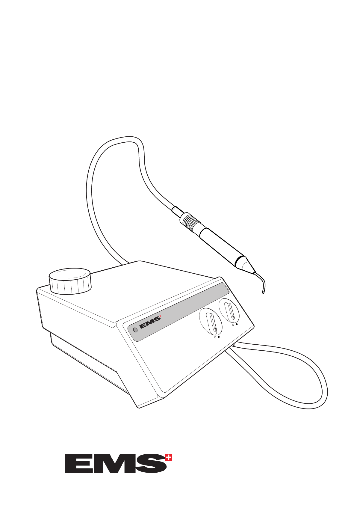
AirFlow® S1
AirFlow
®
S1
Water
Airflow
Service manual
ELECTRO MEDICAL SYSTEMS
1
Page 2

AirFlow® S1
2
Page 3

AirFlow® S1
Table of contents
Important note 5
The unit and its components 6
Installation 6
Technical data 7
Description of the unit 7
Description of the electrical parts 8
Description of the hydraulic parts 10
Description of the pneumatic parts 11
Description of the powder parts 12
Trouble shooting 14
Verication of the general condition (internal) 14
Verication of the primary electrical circuit 14
Verication of the secondary electrical circuit 14
Verication of the water circuit 14
Verication of the air circuit 16
Verication of the powder circuit 16
Opening of the unit 15
Disconnecting of the air, water and powder hoses 16
Replacement of the secondary fuses 17
Unsoldering of the electrical wires 17
Replacement of the primary fuses 18
Assembly of the knob 19
Replacement of the transformer 20
Replacement of the thermostats 21
Replacement of the water heater 22
Procedure in case of heating problem 23
Replacement of the water lter cartridge 24
Replacement of the complete water lter 24
Replacement of the water regulator 25
Replacement of the pneumatic module for polisher 26
Replacement of the air lter element 27
Replacement of the air lters 27
Replacement of the electrovalve 28
Replacement of the air regulator 29
Replacement of the powder bowl set 30
Replacement of the pinch valve 31
Spare parts & Update 32
Spair part View 33-35
Function control 36
Safety control 36
EMS reserves the right to modify the technic, accessories, operating instructions or
the contents of the AirFlow® S1 due to technical or scientic improvements.
3
Page 4

AirFlow® S1
4
Page 5
AirFlow® S1
Important note
As manufacturer of electrical/medical devices, our responsibility
extends to the technical safety features of the unit only if mainte-
nance, repairs and modications are carried out by a repair center
trained and authorized by EMS.
All repairs or revisions must be carried out with the original EMS
spare parts.
The EMS quality policy requires a function control for each intervention and a safety control for each intervention requiring the
opening of the unit.
Each intervention of units for repair or revision must be docu-
mented.
For each return addressed to EMS, please clean and disinfect the
AirFlow® as described in the operating instructions and sterilize
the handpiece.
The boards must be wrapped in an antistatic bag.
This unit may not be operated in an explosion hazardous environ-
ment.
5
Page 6
AirFlow® S1
Water
Airow
AirFlow
®
S1
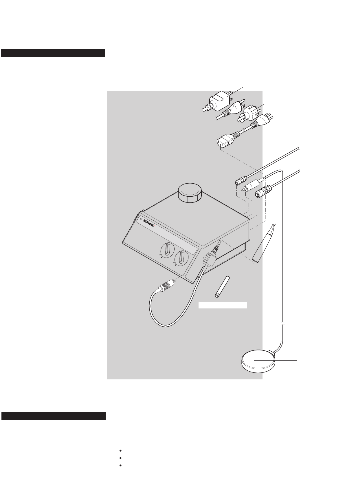
The unit and its components
Installation
Mains 100 - 110 V AC
Mains 220 - 240 V AC
Water pressure
1 - 5 bar
Compressed air
4.5 - 7 bar
Polisher handpiece
Spanner for water lter
Footswitch
6
Installation
The following connections are required to operate the
unit :
A water supply of between 1 and 5 bars
A compressed air supply of between 4.5 and 7 bars
An electrical supply.
Page 7
Technical data
Technical data
Manufacturer: EMS SA - 1260 Nyon, Switzerland
Models: AirFlow® S1
Classication: EN 60601-1 Class I
Type B
IP 20
93/42 CEE: Class IIa
Mode of operation: Continuous operation
Supply voltage: 100 V AC / 110 V AC
220 V AC
240 V AC
Main frequency: 50 - 60 Hz
Power consumption: max. 75 VA / for CSA units 115 VA*
Fuses Primary: ø 5 x 20 mm, 250 V
for 100V AC/110V AC, T 1 A, time-lag
for 220V AC/240V AC, T 0.5 A, time-lag
Secondary: ø 5 x 20 mm, 250 V, T 2.5A, time-lag
Compressed air supply: 4.5 to 7 bar (450 to 700 kPa) >15 Nl/min
(66 to 102 Psi)
Water supply: Cold water 1 to 5 bar (100 to 500 kPa)
(15 - 73 Psi)
Operating conditions: +10
30% to 75% relative humidity
Storage and transport
conditions: -10oC to +40oC (+14F to 104F)
10% to 95% relative humidity
Air pressure: 500 hPa to 1060 hPa
Weight: Approx. 3.6 kg (8.1 lbs)
Dimensions: Height: 120 mm
Width: 250 mm
Length: 250 mm
o
C to +40oC (+50F to 104F)
* For units sold in the USA and Canada
Description of the unit
The powder unit of the AirFlow® S1 is primarily intented for removing soft deposits and discolourations from all visible areas of teeth
as well as from ssures and interdental spaces.
The AirFlow® S1 is driven by a pneumatic footswitch.
7
Page 8
AirFlow® S1
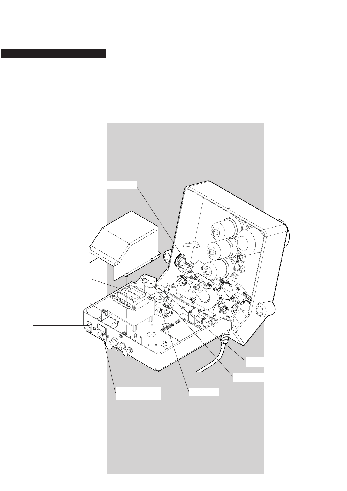
Description of the electrical parts
This unit is equipped with a mains socket with fuses incor-
porated. The main switch ON/OFF is placed on the back
side of the unit.
The mains voltage (high voltage of 110, 220 or 240 V AC)
is converted into 24V AC (low voltage), by an internal trans-
former, to supply all the electrical components of the unit.
Transformer
Secondary fuse
Main switch
Electrovalve
8
Mains socket
and primary fuses
Thermostat 47°C
Thermostat 60°C
Water heater
Page 9
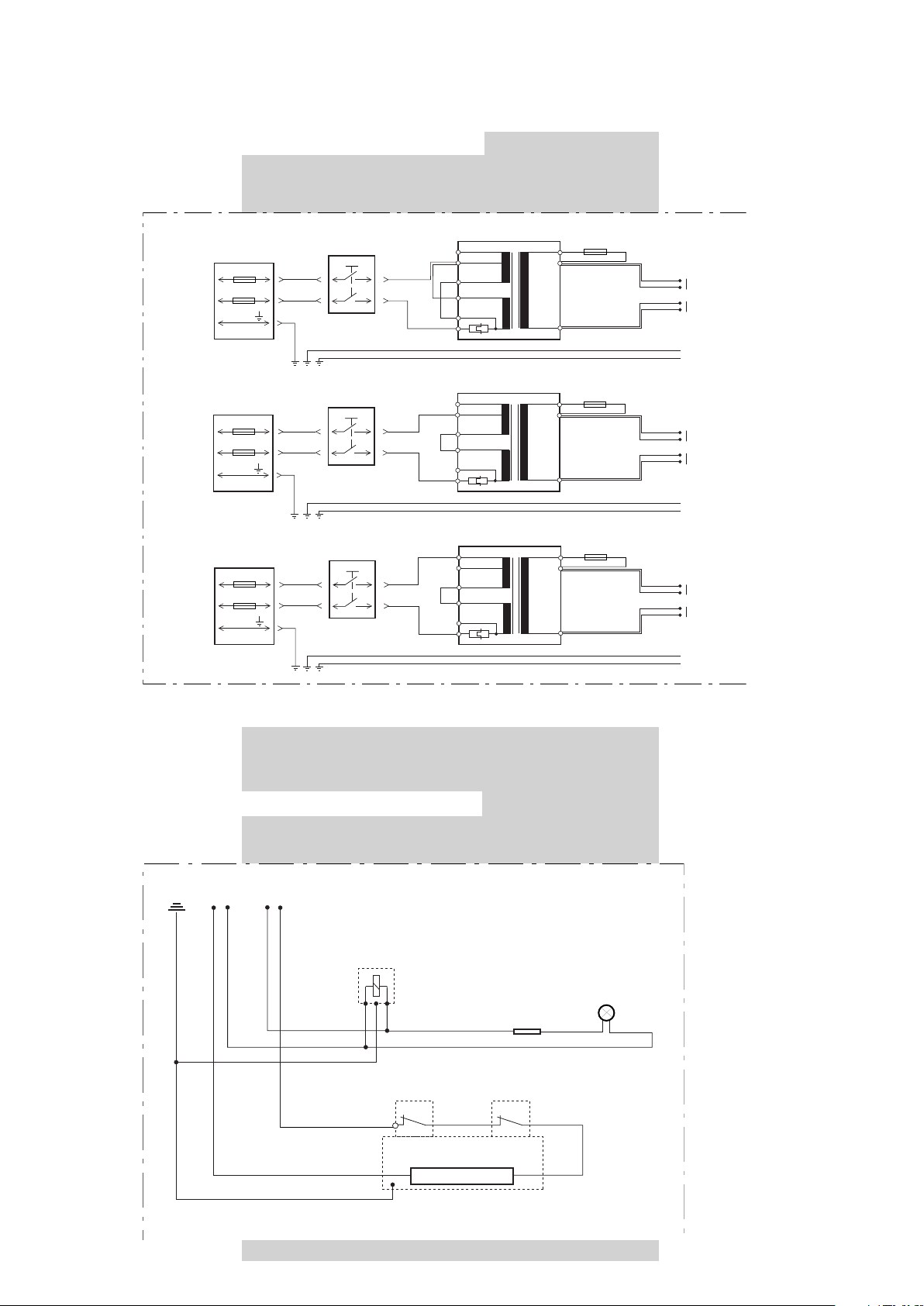
AirFlow® S1
Blue
24 V AC
Green LED
Resistance
+-
Electrovalve
Blue
Blue
Blue
Blue
Blue
Thermostat
Red
47˚C
Thermostat
60˚C
Red
Water heater
Green/Ye llow
Red
Red Red
Red
Red
Red
Black
Secondary fuse
T 2.5A
Transformer
*
Main switch
Mains socket
T 1A
Primary fuses
T 1A
Yellow/
Green
ON/OFF
11
1
2
4
3
5
6 240 V
130 V
220 V
110 V
8
9
Red
Black
Secondary fuse
T 2.5A
Transformer
*
Main switch
Mains socket
Yellow/
Green
ON/OFF
11
1
2
4
3
5
6 240 V
130 V
220 V
110 V
8
9
Red
Black
Secondary fuse
T 2.5A
Transformer
*
Main switch
Mains socket
Yellow/
Green
ON/OFF
11
1
2
4
3
5
6 240 V
130 V
220 V
110 V
8
9
110 V AC
220 V AC
240 V AC
Red
Red
Red
Red
Red
Black
Black
Black
T 0.5A
Primary fuses
T 0.5A
T 0.5A
Primary fuses
T 0.5A
Blue
24 V AC
Red
Blue
Red
Blue
24 V AC
Red
Blue
Red
Blue
24 V AC
Red
Blue
Red
Yellow/Green
Yellow/Green
Yellow/Green
Yellow/Green
Yellow/Green
Yellow/Green
Primary circuit (high voltage)
*For the transformers without thermal protection (no pin 1), connect the black wire on pin 2.
Secondary circuit (low voltage)
9
Page 10
AirFlow® S1
Polisher
handpiece cord
Additional connections available for AirFlow® S2
Water filter on
AirFlow® S1
Pneumatic
module for
polisher
Water heater
Polisher
connector
Polisher handpiece
Water
regulator
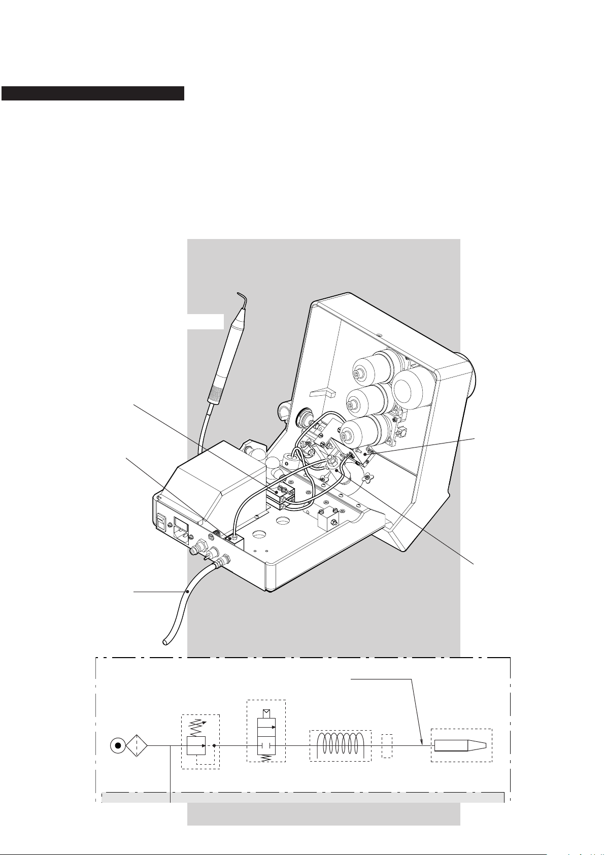
Description of the hydraulic parts
AirFlow® S1 is equipped with a water lter at the entrance
of the water supply. Water circuit is made by blue hoses.
On the AirFlow® unit, the water passes through a water
lter then though a water regulator allowing the regulation
of the ow, and goes into the pneumatic module driven by
the electrovalve, the heater and the polisher handpiece via
the handpiece cord.
Water heater
Water lter
Water supply
Polisher handpiece
Pneumatic module for
polisher
Water regulator
10
Page 11
AirFlow® S1
See water circuit
Pneumatic module for polisher
Electrovalve
Pinch valve
Footswitch
Powder bowl set
Air filterAir filterAir filter
Air regulator
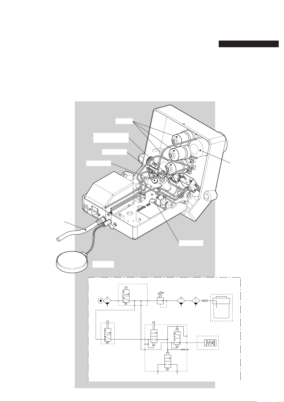
Description of the pneumatic parts
AirFlow® S1 unit is driven by a pneumatic footswitch. Internal air
circuit is made by yellow hoses.
It is equipped with an air lter at the entrance of the air supply.
The air passes through a regulator allowing the regulation of the
ow, and goes into the a set of two air lters before its entrance
into the powder bowl.
The pneumatic module for polisher, the pinch valve and the water
circuit are driven by the air circuit.
Air lter
Pneumatic module
for polisher
Air supply
Electrovalve
Air regulator
Footswitch
Powder bowl set
Pinch valve
11
Page 12
AirFlow® S1
Polisher
handpiece cord
Powder bowl set
Pinch valve
Polisher
connector
Polisher handpiece
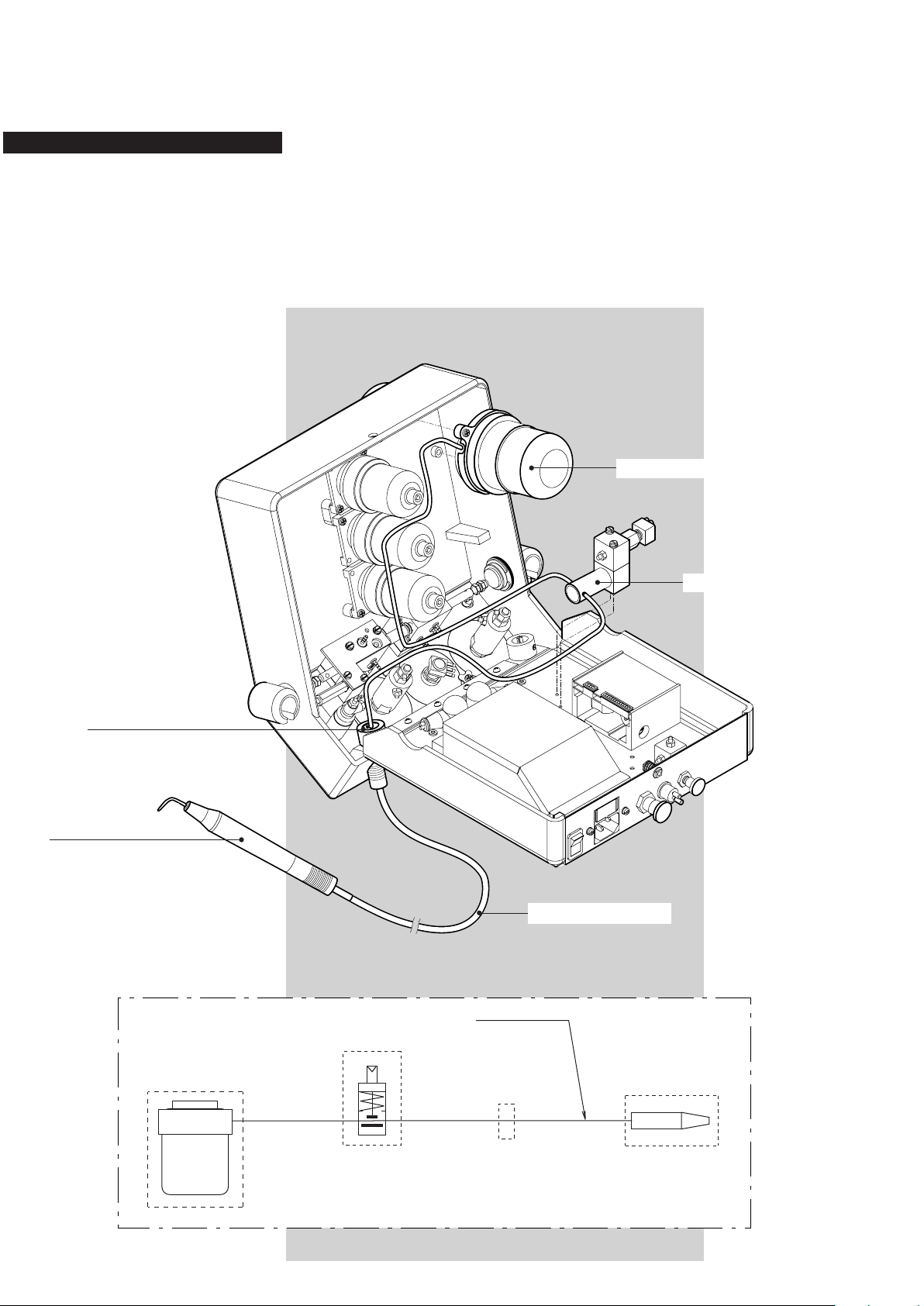
Description of the powder parts
The powder circuit is used on the AirFlow® system. The
powder circuit is made by a transparent hose.
The powder comes from the powder bowl and passes
through the pinch valve allowing the stop of the ow, and
goes into the polisher handpiece via the handpiece cord.
Powder bowl set
Polisher connector
Polisher handpiece
Pinch valve
Polisher handpiece cord
12
Page 13

Notes
Remarks and observations
13
Page 14

AirFlow® S1
Trouble shooting
-
-
°
°
14
≤ ≤
≤ ≤
≤ ≤
≤ ≤
* Replacement do not need the opening of the unit
Page 15

Opening of the unit
83
Remove the screw (83) and open the upper casing by
lifting up from the closed position.
The assembly of the upper part and the lower part of the
unit is made by the hinge (86).
86
15
Page 16

AirFlow® S1
* Replacement do not need the opening of the unit
Disconnecting of the air, water and powder hoses
In all cases, remove rst the external collar and after the
conical part of the uniclamp (92).
Remove the hose (66, 70 or 85) from the tubing of the element.
66
70
85
92
16
Page 17

Replacement of the secondary fuse
FUSE
T
2.5
AMPS
Turn the fuse holder head (82) on the anticlockwise and
extract the fuse (81).
Replace the fuse following the specications mentioned
on the sticker.
Sticker
82
81
Unsoldering of the electricawires
In all cases, before to unsolder the wires on the
electrical connexion, remove the insulated sleeving.
Connector
Insulated sleeving
17
Page 18

AirFlow® S1
FUSES
100-110V
T 1 A
220-240V
T 500mA L
I
O
Replacement of the primary fuses
Open the unit (see page 15).
Apply a lateral slight pressure with a small screwdriver on
the fuse holder (78) and extract the fuses (77).
Replace the fuses following the specications mentioned
on the sticker at the rear of the unit.
18
78
77
Sticker
Page 19

Assembly of the knob
The regulators and taps sent for After Sales Support
are ADJUSTED and TESTED to function correctly.
Don’t modify the adjustment before assembly.
Preparation of the regulator holder
Cut the three external pins coming from the moulding.
Lay down a lm of silicone paste on the contact surface
between the knob and the holder.
Assembly instructions
Put the knob (68) and the elastic washer (69) into the knob
holder of the regulator in such a way that the stop of the
knob is as close as possible to the stop of the knob holder
(on the left). Do not turn the axis of the regulator. The knob
should be able to turn in a clockwise direction (thus open-
ing the regulator).
Turn the knob anticlockwise (0o-15o) to join the 2 stops. The
regulator is now at minimum position.
69
Silicone paste
Regulator axis
68
Stop on the regulator
holder
Stop on the knob
Put the assembly into the upper casing of the unit (from
inside), the spot of the knob should be opposite to the spot
on the casing .
Spot of the knob
Spot on the casing
19
Page 20

AirFlow® S1
Replacement of the transformer
Remove the three screws (90) of the metal housing of the
transformer (64).
Remove the housing of the transformer and extract the
bushing (93).
Remark: note the order of connection for each wire.
Unsolder all the electrical cables of the transformer (65).
Remove the four screws (83) and the washers (74) of the
transformer.
Put in place a new transformer.
65
90
64
93
20
74
83
Page 21

Replacement of the thermostats
This procedure is identical for the thermostat 60oC (28)
and for the thermostat 47oC (29) screwed on the top of the
water heater (30).
Remove the thermostat protection (27).
Unsolder the two cables on the thermostat.
Unscrew the thermostat using the two pins for electrical
connection.
Put in place a new thermostat.
27
28
29
30
21
Page 22

AirFlow® S1
Replacement of the water heater
Remove the three screws (90) of the metal housing of the
transformer (64).
Remove the housing of the transformer and extract the
bushing (93).
Unsolder the electrical wires on pin 11 of the transformer
(65) and extract the electrical wire of the water heater from
the bushing.
Remove the thermostat protections (27) and unsolder the
four electrical wires on the thermostats (28) and (29).
Extract the electrical wire of the water heater from the ther-
mostat protection.
Remove the two uniclamps (92) and disconnect the blue
water hoses (70) from the water heater (30).
Unscrew the ground connection (31).
Remove the two screws (25) and the two washers (26).
Put in place a new water heater.
The water heater is mounted
on two insulating cannons (32).
28
30
64
90
25
26
27
31
29
92
70
32
22
93
65
Page 23

Procedure in case of heating problem
Switch the power ON and verify (by hand) the increase of
temperature of the water heater (30). If the heater stays cold,
use the following procedure to identify if the problem is due
or not to the thermostats.
Shunt (A) the thermostat 47oC (29) and control the increase
of temperature of the heater.
If the heater starts to be warm, it means that the
thermostat 47oC is out of order and it must be re placed by a new one (see page 21).
If no increase of temperatue appears, try to rearm
the thermostat 60oC (28) by pushing the pin down.
In case of the pin stays up, it means that the
rearmament system is out of order and the ther mostat 60oC must be replaced by a new one (see
page 21).
In case of the pin stays down (good rearmament),
and if the heater doesn’t work, shunt the thermos-
tats 47oC (A) and 60oC (B) at the same time.
At this step, if no heating is produced, control the electrical
supply of the water heater (see page 9).
Pin
28
29
30
Shunt B
Shunt A
23
Page 24

AirFlow® S1
Replacement of the water lter cartridge
Unscrew the cap of the water lter (38) on the back side
of the unit.
Unscrew the water lter cartridge using the hexagonal
spanner (10).
Change the water lter spare parts set (39).
Replacement of the complete water lter
Dismantle the uniclamp (92) and disconnect the blue water
hose (70) from the water lter.
Unscrew the external nut of the water lter and put in place
a new complete water lter (38).
38
External nut
92
70
24
10
39
Water lter cap
Page 25

Replacement of the water regulator
Dismantle the two uniclamps (92) and disconnect the blue
water hoses (70) from the regulator.
Remove the two screws (90) and the elastic washers (89)
of the knob.
Extract the water regulator (91) and the knob (68) from
inside of the casing.
Remove the knob from the water regulator.
Put in place a new water regulator (see page 19).
70 92
91
90
89
68
25
Page 26

AirFlow® S1
Replacement of the pneumatic module for
polisher
Remove the two screws (63) and the washers (26).
Release the electrovalve (23) and its plate (21).
Extract the selector rod (22) from the module.
Remove the ve uniclamps (92) and disconnect the three
yellow air hoses (66) and the two blue water hoses (70)
from the pneumatic module for polisher (62).
Put in place a new pneumatic module for polisher.
22
92
21
23
70
63
26
62
92
66
26
Page 27

Replacement of the air lter element
Unscrew the air lter bowl (59).
Unscrew the air lter element (60).
Change the air lter element and the O-ring.
Replacement of the air lters
This procedure is identical for :
- the air lter with horizontal L coupling (58),
- the air lter with check-valve (55),
- the air lter with vertical L coupling (54).
Remove the two screws (61).
Dismantle the two uniclamps (92) and disconnect the
yellow air hoses (66) from the air lter.
Put in place a new air lter.
61
59
92
66
O-ring
60
58
61
54
55
27
Page 28

AirFlow® S1
Replacement of the electrovalve
Remove the two screws (63) and the washers (26).
Release the plate support (21) of the electrovalve and re-
move the two plastic screws (20).
Disconnect the three electrical connectors from the elec-
trovalve.
Disconnect the four uniclamps (92) and the yellow air hoses
(66) from the electrovalve (23).
Put on a new electrovalve in replacement.
Place the seal (included with the electrovalve set)
between the electrovalve and the plate support.
92 66 20
Seal
23
21
63 26
28
Page 29

Replacement of the air regulator
Remove rst the two screws (63) and the washers
(26) of the pneumatic module for polisher to allow
a free access to the xation of the air regulator.
Dismantle the two uniclamps (92) and disconnect the yellow
air hoses (66) from the regulator.
Remove the two screws (90) and the elastic washers (89)
of the knob.
Extract the air regulator (67) and the knob (68) from inside
of the casing.
Remove the knob from the air regulator. Put in place a new
air regulator (see page 19).
66
92
67
68
90
89
2663
29
Page 30

AirFlow® S1
Replacement of the powder bowl set
Unscrew the cap for powder bowl (56) from outside of the
unit.
Remove the two screws (34) and the washers (26).
Dismantle the two uniclamps (92) and disconnect the yellow
air hose (66) and the transparent powder hose (85) from
the powder bowl set (35).
Put in place a new powder bowl set with the two O-rings
(33 and 37).
92 66
92
85
34 26 37 33
35
36
57
56
30
Page 31

Replacement of the pinch valve
Remove the two screws (25) and the washers (26).
Dismantle the two uniclamps (92) and disconnect the trans-
parent powder hose (85) from the polisher connector (48).
Remove the transparent powder hose passing through the
pinch valve hole.
Dismantle the uniclamp (92) and disconnect the yellow air
hose (66) from the pinch valve (24).
Put in place a new pinch valve and a new powder hose.
92
48
85
25
26
24
92
66
31
Page 32

AirFlow® S1
-The Spare parts catalogue #1 dent refer to FM-058/*
- AF Handpiece EL-085 + EL-086 + EM-061
are Discontinued
Spare parts & Update
Replace by EQ-160
-The solnoide valv EQ-024 replace by EQ-159
-The powder tube BG-006 replace by EQ-207
32
Page 33

AirFlow® S1
22
23
20
21
24
25
26
27
28
29
63
26
62
25
26
61
59
60
58
59
38
39
42
43
44
35
36
34
30
37
26
40
41
33
31
32
52
53
54
55
57
56
45
46
47
48
49
51
50
33
Page 34

AirFlow® S1
90
93
65
64
26
72
26
73
74
72
66
67
71
68
69
70
69
92
91
90
89
83
104
88
79
78
77
76
75
80
81
82
84
87
86
85
74
83
83
34
Page 35

AirFlow® S1
Pos. Designation Order No.
20 Plastic screw for electrovalve DD-037
21 Plate for electrovalve BE-003
22 Selector rod EQ-023
23 Electrovalve EQ-159
24 Pinch valve + holder EH-034
25 Screw for heater & pinch valve DD-030
26 Washer M3 DF-017
27 Thermostat protection AP-001
By position
28 Thermostat 60oC CF-004
29 Thermostat 47oC CF-006
30 Water heater EK-015
30 Water heater CSA* EK-107
31 Screw for heater ground DD-025
32 Insulating cannon for heater CH-041
33 O-ring for powder bowl BC-006
34 Screw for powder bowl DD-609
35 Powder bowl set EH-007
36 Powder bowl AB-002B
37 O-ring for powder bowl BC-017
38 Water lter complete EG-004
39 Water lter spare parts set EQ-029
40 Screw front panel connector DD-003
41 Washers for handpiece holder EQ-011
42 Locking set EQ-010
43 Air inlet connector EQ-005
44 Protection cap air connector AQ-016
45 Protection caps for footswitch AQ-013
connectors
46 Footswitch inlet connector EH-022
47 Protection cap water connector AQ-015
48 Polisher connector EG-013
49 O-ring for polisher connector BC-035
50 Set of 4 stoppers EQ-015
51 Green control light CH-031
52 Resistance 470 Ohms CJ-010
53 Push button AD-056
54 Air lter - vertical L coupling EQ-064
55 Air lter with check-valve EQ-066
56 Cap for powder bowl + O-ring EQ-019A
57 O-ring for Air-Flow cap BE-009
Pos. Designation Order No. Pos. Designation Order No.
58 Air lter - horizontal L coupling EQ-065
59 Air lter bowl + O-ring EQ-020
60 Kit Air lter element + O-ring EQ-152
61 Screw for air lters DD-608
62 Pneumatic module for polisher EH-006
63 Screw for polisher module DD-032
64 Metal housing for transformer AL-004
65 Transformer CC-008A
66 Yellow air hose BG-004
67 Air regulator + holder EH-014
68 Knob AB-011H
69 Elastic washer for knobs DF-042
70 Blue water hose BG-005
71 Handpiece holder right AA-041E
72 Nut ground conn.- mains socket DE-006
73 Nut for ground connection DE-002
74 Washer M4 DF-018
75 Mains socket CH-034
76 Screw for base and mains socket DD-026
77 Fuse T 1A (100/110 V AC) CE-033
77 Fuse T 0.5A (220/240 V AC) CE-027
78 Fuse holder CE-019
79 Main switch CE-013
80 Fuse holder CE-009
81 Fuse T 2.5A CE-025
82 Fuse holder head CE-010
83 Screw for ground, transfo & locking DD-035
84 Screw for ground DD-027
85 Powder tube replacement kit EQ-207
86 Hinge AQ-028A
87 Screw for hinge DD-607
88 Hinge plate AL-005
89 Elastic washer for knob screw DA-009
90 Screw for knobs & metal housing DD-602
91 Water regulator + holder EG-076
92 Uniclamp BG-001
93 Bushing for transformer housing CG-007
104 Upper case AA-038J
105 Front Label DQ-332
35
Page 36

AirFlow® S1
Function control
Use the “Trouble shooting” to control the functioning of the unit
after each repair.
Indicate on the data sheet the serial number of the unit, the result
of the controlled points and the part exchanged.
Date and sign the data sheet and transmit a copy to the After Sales
Service in Nyon for information.
Uae the Deat Sheet fonction control ZA-176.
Safety control
The EMS quality policy requests a safety control for each repair
requiring the opening of the unit.
Use the safety control procedure of the SAV FM-010.
36
Page 37

Notes
Remarks and observations
37
Page 38

Notes
Remarks and observations
Page 39

Page 40

SWITZERLAND
EMS SA, Ch. de la Vuarpillière 31, CH-1260 Nyon
Tel. +41 22 99 44 700, Fax +41 22 99 44 701
e-mail: welcome@ems-ch.com
website: www.emsdent.com
FM-003/EN Ed.2013/01
 Loading...