

Page 1

7258 UHF Remote Receiver
Operating Instructions
©2018 EMS Ltd. All rights reserved. Page 1 of 16 MK108 Iss4 27/07/2018 AJM
Page 2

Contents
Introduction 3
Wiring Details 3
Tools & Test Equipment 5
Remote Receiver Positioning 5
Electrical Installation 5
Software Conguration 6
Iris+ Main Menu 6
Main Iris+ Receiver Software Conguration 7
Testing the System 9
Measuring the Background Level 9
On-site Range Testing 10
Site Testing with a Pager 10
Site Testing (Single Person) 11
Site Testing (Two Person) 12
Commissioning & Programming 13
Wiring 14
©2018 EMS Ltd. All rights reserved. Page 2 of 16 MK108 Iss4 27/07/2018 AJM
Page 3

Introduction
The Remote Receiver for the Iris+ is designed to extend the systems wireless coverage. This is
usually necessary where the premises to be protected occupies a large area, is spread over
many oors or is in an area which is subject to high levels of radio interference.
The Remote Receiver units are all coded to allow individual identication. This code number
(3-31) can be located on the rear of the unit and also internally. When adding additional
Remote Receivers to a site, the existing receiver code numbers can be viewed from the Iris
receivers menu structure. For a step by step guide to viewing the devices code numbers, refer
to the ‘Main Iris+ Receiver Software Conguration’ section.
Important Note:
Before commencing the installation, check that all Receivers which are to be connected to the
Iris+ have dierent NUA code numbers from any other new / existing Remote Receivers, to ensure
correct operation.
The Remote Receiver is hardwired to the Iris+ using screened 4 core cable. Up to 28 Remote
Receivers can be connected to the Iris+. The presence of one or more Remote Receivers is
transparent to the user.
Wiring Details
The Remote Receivers and the Iris+ must be wired together in a daisy chin style. The Iris+ can
be positioned anywhere along this cable run. Under no circumstances should the units be
wired in a star conguration. The maximum overall cable run for the RS485 Bus is 1000
metres. A block diagram showing examples of correct / incorrect Remote Receiver wiring is
shown overleaf in Figure 1.
©2018 EMS Ltd. All rights reserved. Page 3 of 16 MK108 Iss4 27/07/2018 AJM
Page 4
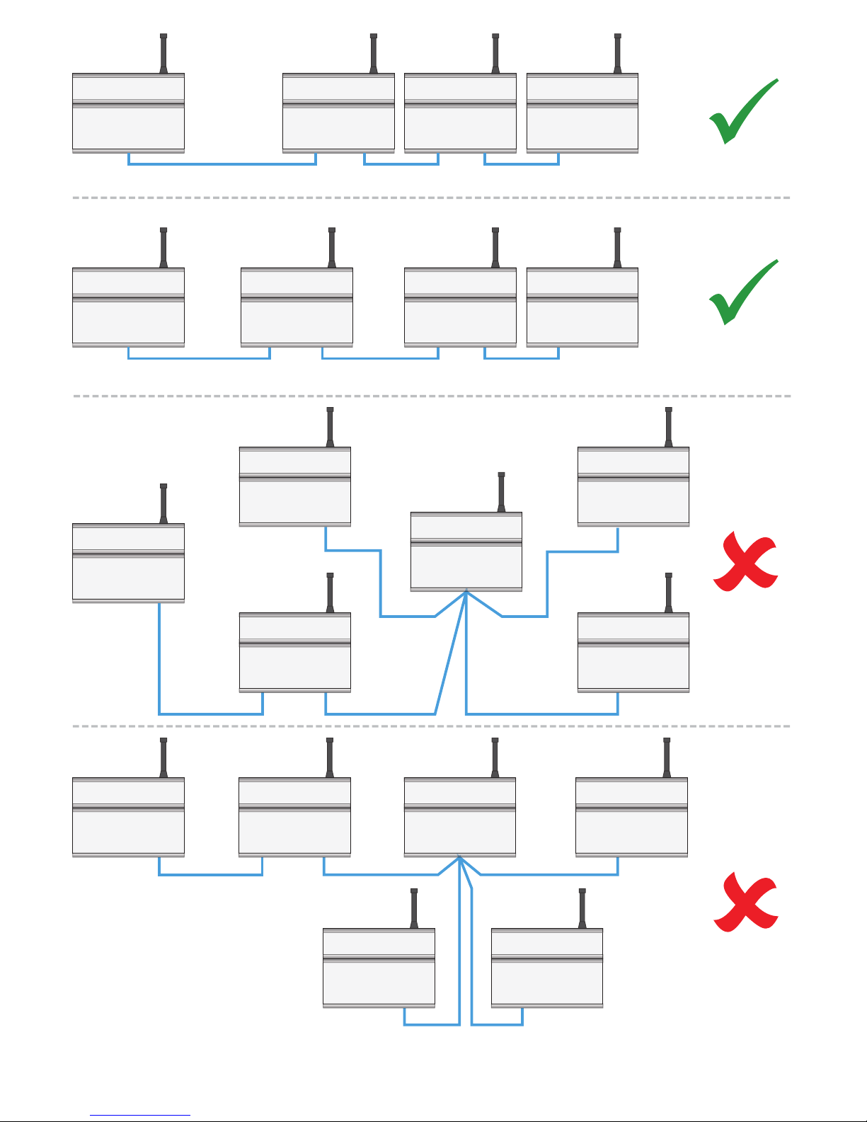
Iris+
Remote Receivers
End
Of
Line
Iris+
Remote Receivers
End
Of
Line
Remote Receiver
No End Of Line
Required
Iris+
Remote
Receivers
Remote
Receivers
Figure 1
Iris+
Remote
Receivers
Remote Receiver
©2018 EMS Ltd. All rights reserved. Page 4 of 16 MK108 Iss4 27/07/2018 AJM
Page 5

Tools & Test Equipment
No special test equipment is needed when installing the Remote Receiver. Only standard
hand tools are required to install and commission the wireless system. Beldon four core
screened cable is recommended for the connection between Remote Receivers and the Iris+
Receiver. It is also recommended that the Iris+ Engineers Programming Manual is available
when commissioning a remote receiver.
Remote Receiver Positioning
The maximum range between a Remote Receiver and any transmitter is dependant upon the
local environment. A range of up to 250 metres can be obtained although actual range
achieved is determined by site conditions, the quality of the receivers aerial and how well the
system has been installed.
When selecting a site for the receiver, the installing engineer should be aware that the aerial
should be as far as away from electrical / electronic equipment as possible and a minimum of
2 metres from any such equipment. The systems performance will be reduced if the aerial is
closer and will also be reduced by metal objects such as ling cabinets, pipe work, radiators
and air conditioning ducts obstructing the aerial.
Electrical Installation
The Iris+ Receiver and Remote Receivers are supplied with a connection back box and should
be wired as shown on page 14.
The Remote Receiver must NOT be used as a junction box or cable termination point for other
equipment as this will adversely eect performance of the system. Only those cables needed
to make the Remote Receiver function should be fed into the connection back box.
The Remote Receiver case must be earthed. An earthing tag is provided for this purpose. A
tag is located in the connection back box of the Iris+ Receiver. The Iris+ Receiver and Remote
Receivers require a 12Vdc supply. The 0V line should NOT be connected to the same point as
the earth case.
Ensure that the END OF BUS jumper is made on the rst and last receiver in the wiring daisy
chain (See page 4 for further details). The end of bus jumper can be found on the 2411 PCB,
located at the rear of the Iris+ and Remote Receivers door assembly. The jumper is located
top centre of the PCB.
The RS485 port is used as the Remote Receiver Bus. The maximum overall cable run is 1000
metres.
©2018 EMS Ltd. All rights reserved. Page 5 of 16 MK108 Iss4 27/07/2018 AJM
Page 6

Having installed the Iris+ Receiver and Remote Receivers, it is necessary to programme the
Iris+ Receiver to communicate with the Remote Receivers. If the Iris+ Receiver and the
Remote Receivers were supplied as a system, they will be pre-programmed. If however the
Remote Receiver has been ordered and supplied separately, then the system will need to be
congured. This conguration should always be checked (see below).
Software Conguration
To allow the Iris+ Receiver to communicate with the Remote Receivers, the Iris+ will have to
be programmed to re-scan it’s RS485 Bus. This action will locate all Remote Receivers on the
Bus by identifying their code numbers and allow data received my each Remote Receiver to
be passed to the Iris+ Receiver. If the Iris+ Receiver and Remote Receivers have been supplied
as a system, then the Iris+ Receiver will have these functions pro-programmed. It is good
practice to check that the settings are correct.
The relevant menu options are highlighted below in Figure 2. The programming
requirements are shown in a step by step format in the following sections.
Iris+ Main Menu
Main Menu
Pins & Access
System Support
Serial Comms
Txer Setup
Engineers Ctrl
Time & Date
Radio Setup
Output Setup
Logging
Relay Setup
Remote Rxers
Direct Inputs
Time Control
Txer Grouping
Figure 2
The Main Menu can be scrolled through using the & keys on the front keypad of
the Iris+ Receiver.
©2018 EMS Ltd. All rights reserved. Page 6 of 16 MK108 Iss4 27/07/2018 AJM
Page 7

Main Iris+ Receiver Software Conguration
Enter the Engineers Mode by turning the key to RESET and entering the engineering PIN
(221100). The Iris+ Receiver’s menu structure is shown below in Figure 3.
Iris+ Receiver’s Menu Structure
Main Menu
Pins & Access
System Support
Serial Comms
Txer Setup
Engineers Ctrl
Time & Date
Radio Setup
Output Setup
Logging
Relay Setup
Remote Rxers
Direct Inputs
Time Control
Txer Grouping
Serial Comms
Device Table
Restart Bus
Reonline Device
Bus Master Setup
Bus Remote Setup
Pager 232 Redirect
Aux 232 Redirect
Printer Redirect
Monitor Comms
Delete Device
Master Setup
Polling Baudrate
Auto Reonline
Port To Use
Reinitialising Bus
Please Wait...
Push Any Key
Master Port=1,
0= O, 1=RS485,
2=Pager 232
1st Action
2nd Action
From the Iris+ Receiver’s Main Menu:
Use the & keys to scroll through the menu, until >Serial Comms< is
highlighted.
Press the key, to select.
Use the & keys to scroll through the menu, until >Bus Master Setup<
is highlighted.
Press the key, to select.
Use the & keys to scroll through the menu, until >Port To Use<
is highlighted.
Press the key, to select. The following screen prompt will be displayed:
Figure 3
1
1
1
Master Port=0,
0= O, 1=RS485,
2=Pager 232 > _
=Done =Del 14:29
Figure 4
©2018 EMS Ltd. All rights reserved. Page 7 of 16 MK108 Iss4 27/07/2018 AJM
Page 8

Press the key, to change the Master Port to 1, then press the key to conrm
selection. This port number selects which of the output ports is used to be used for
the hardwired connection between the Remote Receiver and theIris+ Receiver.
Press the key once to return to the Serial Comms menu. Use the &
keys to scroll through the menu, until >Restart Bus< is displayed.
Press the key, to select. This will initialise and restart the data bus that the
Remote Receivers are connected to. Press the key when ‘done’ is shown.
Use the & keys to scroll through the menu, until >Device Table< is
highlighted.
Press the key, to select. The Remote Receivers connected to the system can
now be viewed. Use the key to scroll through the display to check that the
Remote Receivers are online. A typical display is shown in Figure 5.
1
3
1
3
1
03/Remote
Receiver, ONLINE
(0,00)
2=Help 14:29
Figure 5
‘Where ‘03’ is the Remote
Receivers NUA code number.
Press the key once to return to the Serial Comms menu. Use the & keys
to scroll through the menu, until >Monitor Comms< is displayed.
Press the key, to select. A typical display is shown in Figure 6.
3
1
HEAP 00 AUX=00 PGR=00
REM 000 MAS 000 T00-00
I 00 L 00 R 00 S 00 C 00
Push Any Key 14:29
Figure 6
The two relevant indicators for the monitoring of the RS485 Bus are described below:
If there is one Remote Receiver
communicating on the RS485 Bus,
the gure will be 10. If there are two
Remote Receivers communicating
on the RS485 Bus, the gure will be
20 and so on.
A time out is where Comms between
the Iris+ Receiver and the Remote
Receiver is lost momentarily.
The number of polls per second ,
from the Iris+ Receiver.
xx is the number of Bus Master
Timeouts that have occurred and
dd is the last device to time out.
MAS xxx
Txx - dd
©2018 EMS Ltd. All rights reserved. Page 8 of 16 MK108 Iss4 27/07/2018 AJM
Page 9

If the system is not performing as expected in terms of range, monitoring the Comms
between the Iris+ Receiver and the Remote Receivers may well indicate a connection
problem. For example, a large number of Time-outs by a particular Remote Receiver, indicates
a poor connection, poor screening, or the cable passing near enough to a data cable to
introduce interference on the Bus. For correct communication, the amount of time-outs
generated by any Remote Receiver must be less than one minute. To check the amount of
time-outs generated, it is necessary to view the ‘Monitor Comms’ display as previously
outlined, for this time period.
Testing the System
Once the Iris+ and Remote Receivers have been installed, the transmitters should be tested to
ensure sitewide coverage is achieved. Each test transmission received by the system will have
a signal strength value, up to a maximum value of 255. To ensure satisfactory communication,
the transmitters signal strength should exceed the Background Level on the Iris+ by 30.
Measuring the Background Level
To measure the Background Interference Level on the Iris+, the following steps will need to be
carried out. Turn the Iris+ control key to the Reset Position. Press the key and enter the
engineers pin number to access the Main Menu.
From the Main Menu:
Use the & keys to scroll through the menu, until >Radio Setup< is
highlighted.
Press the key, to select.
Use the & keys to scroll through the menu, until >Test Routines< is
highlighted.
Press the key, to select.
Use the & keys to scroll through the menu, until >Monitor Carrier< is
highlighted.
Press the key, to select.
A typical carrier display is shown below. See the Iris+ Instructions for further
information if required.
1
0
1
1
Monitor Carrier
Level = 26
Highest = 27
14:30
Figure 7
©2018 EMS Ltd. All rights reserved. Page 9 of 16 MK108 Iss4 27/07/2018 AJM
Page 10

Press the key to back out of the menu structure.
Example 1. Transmitter test transmission signal strength value
Iris+ Background Interference Level
Example 2. Transmitter test transmission signal strength value
Iris+ Background Interference Level
3
150
- 45
105
OK
65
- 45
20
Suspect
!
Therefore, as 20 is less than 30, the signal strength is suspect and reception of signal may be
marginal.
On-site Range Testing
The method of fully testing the system is dependant upon the facilities available to the
commissioning engineers carrying out the range test.
If a paging system is linked to the Iris+ Receiver, full coverage testing can be carried out by
one person with a pager receiver.
If the paging option is not available it would be necessary to re-visit the Iris+ Receiver after
each transmission or communicate back to a colleague situated at the Iris+, using two way
radio etc. to check the signal has been received.
Site Testing with a Pager
To test the system with the availability of on-site paging, the following steps should be taken:
On the Iris+ Receiver, turn the Control Key to the ‘Test’ position.
Turn the Pager Receiver On.
Generate an alarm transmission from the transmitter (push top button for example)
The pager receiver should now receive a signal. An example of a received test
message is shown in the following display:
TEST 192 Local: Hand
Push 001
©2018 EMS Ltd. All rights reserved. Page 10 of 16 MK108 Iss4 27/07/2018 AJM
Page 11

The 192 example number shown is the signal strength, received by the Iris+
Receiver from the transmitter at its tested position. (Maximum reading available is
255).
This number should be noted along with the position of the transmitter for future
reference.
Continue the testing until signal strength readings have been successfully taken from
all points of required coverage. Return the Iris+ Control Key to the ‘Clear Position’ on
completed tests.
Site Testing (Single Person)
For one person to test the system without the availability of onsite paging, the following
steps should be carried out:
On the Iris+ Receiver, turn the Control Key to the ‘TEST’ position.
Generate a transmission from the transmitter (push top button for example).
The Iris+ Receiver should now receive a signal. An example of a received test
transmission is shown in the following display:
Hand Push 001 TEST
192
Local
^ to END 14:31
Note: On an activation, the transmitter actually sends three transmission bursts. This will be
seen by the signal strength reading number varying accompanied by a short buzzer for each
transmission. If a transmission is seen by two receivers on the system i.e. Iris+ Receiver and a
Remote Receiver, or even two separate Remote Receivers, the test signals displayed will be
updated in quick succession. The highest value seen should be noted. The value shown is not
able to identify which receiver has actually received the signal. If this method of testing is
required, refer to page 13.
The 192 example shown is the signal strength received by the Iris+ receiver from the
transmitter at its tested position. Maximum reading available is 255.
Return to the Iris+ Receiver and note this number along with the position of the
transmitter for future reference.
Continue the testing until the signal strength readings have been successfully taken
from all points of required site coverage. Return the Iris+ Control key to the ‘Clear’
position on completion of tests.
©2018 EMS Ltd. All rights reserved. Page 11 of 16 MK108 Iss4 27/07/2018 AJM
Page 12

Site Testing (Two Person)
If a two way radio is available, one person will need to stay at the Iris+ Receiver, whilst the
second will be required to carry out the following steps:
One the Iris+ Receiver, turn the Control key to the ‘Test’ Position.
Generate a transmission from the transmitter (push the top button for example)
The Iris+ Receiver should now receive the signal. An example of a received test is
shown on the following display:
Hand Push 001 TEST
192
Local
^ to END 14:31
Note: On an activation, the transmitter actually sends three transmission bursts. This will be
seen by the signal strength reading number varying accompanied by a short buzzer for each
transmission. If a transmission is seen by two receivers on the system i.e. Iris+ Receiver and a
Remote Receiver, or even two separate Remote Receivers, the test signals displayed will be
updated in quick succession. The highest value seen should be noted. The value shown is not
able to identify which receiver has actually received the signal. If this method of testing is
required, refer to page 13.
The 192 example shown is the signal strength received by the Iris+ receiver from the
transmitter at its tested position. Maximum reading available is 255.
Speak to colleague and ask for the new signal value. Note this number along with the
position of the transmitter for future reference.
Continue the testing until the signal strength readings have been successfully taken
from all points of required site coverage. Return the Iris+ Control key to the ‘Clear’
position on completion of tests.
If the required range is not achieved, the following options are available:
1
2
3
4
Fit a high gain UHF antenna to the nearest receiver.
Add additional Remote Receiver
Shift the position of a high gain antenna to a maximum of 20m
away from the receiver using RG213 low loss co-axial cable.
Move the nearest receiver to a more favourable position, away
from the likely source of interference.
EMS Part no 7328
EMS Part no 7258
©2018 EMS Ltd. All rights reserved. Page 12 of 16 MK108 Iss4 27/07/2018 AJM
Page 13

Intimate testing of the system which requires the mapping of coverage areas for each Remote
Receiver is achievable. This will require the disconnecting of the aerial connector for all other
receivers than the one to be tested. Then return to the ‘On-Site Range Testing’ section on page
10, and plot the readings for the individual receiver.
This will need to be repeated for each receiver in turn until a full coverage map is formed. It is
recommended that areas of coverage overlap as shown in the example below.
Commissioning & Programming
The Iris+ Receiver is pre-congured before leaving the factory. A computer print out is
included with the equipment, showing the setup of the system. Should it be necessary to
alter the setup, consult the programming guide for details on how to reprogram the Iris+
Receiver.
Remote
Receiver
Area
Covered
Remote
Receiver
Remote
Receiver
Iris+
Receiver
©2018 EMS Ltd. All rights reserved. Page 13 of 16 MK108 Iss4 27/07/2018 AJM
Page 14

Remote Receiver Back
1.25A Fuse
RLY2
CON3
L1
BOX
TAMPER
1CON5
1CON4
IC1
IC2 IC3 IC4
Iris +12V OUT
INPUT 8
INPUT 7
INPUT 6
INPUT 5
INPUT 4
INPUT 3
INPUT 2
INPUT 1
OPTO 0V
Iris 0V OUT
0V
+12V
A
COM
B
A
COM
B
A
COM
B
N.O
COM
N.C
POWER
SUPPLY
RELAY
3
RELAY
2
RELAY
1
ALARM
RELAY
HARDWIRED INPUTS
CTS
RX
0V
DTR
TX
PAGER 232
OUT-
OUT+
IN-
IN+
A
B
A
B
+
-
RX
0V
TX
RS485
AUX
RS232
TAMPER
IN
TAMPER
OUT
REMOTE
BUZZER
1.25A Fuse
CON3
L1
BOX
TAMPER
1CON5
1CON4
0V
+12V
POWER
SUPPLY
OUT-
OUT+
IN-
IN+
A
B
A
B
RS485
TAMPER
IN
TAMPER
OUT
12Vdc Input
750mA MIN
To Next Remote Receiver
(IN)
- +
+
-
Wiring
Iris+ Receiver Back box
©2018 EMS Ltd. All rights reserved. Page 14 of 16 MK108 Iss4 27/07/2018 AJM
Page 15

©2018 EMS Ltd. All rights reserved. Page 15 of 16 MK108 Iss4 27/07/2018 AJM
Page 16

©2018 EMS Ltd. All rights reserved. Page 16 of 16 MK108 Iss4 27/07/2018 AJM
EMS Ltd.
Technology House
Sea Street, Herne Bay,
Kent, CT6 8JZ.
t: +44 (0) 1227 369570
f: +44 (0) 1227 369679
www.emsgroup.co.uk
 Loading...