

Page 1
5000
VHF & UHF
REMOTE RECEIVERS
INSTALLATION AND PROGRAMMING
INSTRUCTIONS
MODEL NUMBERS
53 -5414 & 53 –5428
Page 2

EMS 5000 FIREPOINT
2
Table of Contents
Section Page No
1. INTRODUCTION ................................................................................................ 3
2. TOOLS & TEST EQUIPMENT ................................................................................ 4
3. RECEIVER POSITION ......................................................................................... 4
4. UHF REMOTE RECEIVER RELEVANT HIGH GAIN AERIALS ....................................... 4
5. VHF REMOTE RECEIVER RELEVANT HIGH GAIN AERIALS ....................................... 5
6. ELECTRICAL INSTALLATION ............................................................................... 5
6.1 UHF REMOTE RECEIVER ............................................................................................................................................. 5
6.2 VHF REMOTE RECEIVER ............................................................................................................................................. 6
7. SOFTWARE CONFIGURATION ............................................................................. 7
8. MAIN CONTROL PANEL ENGINEERS MENU STRUCTURE ......................................... 11
9. TESTING THE SYSTEM ...................................................................................... 12
10. CONTROLLER INFORMATION ........................................................................... 15
©2015 EMS Security Group Ltd. All rights reserved. TSD244 Iss 3 25/06/15 AJM
Page 3
EMS 5000 FIREPOINT
3
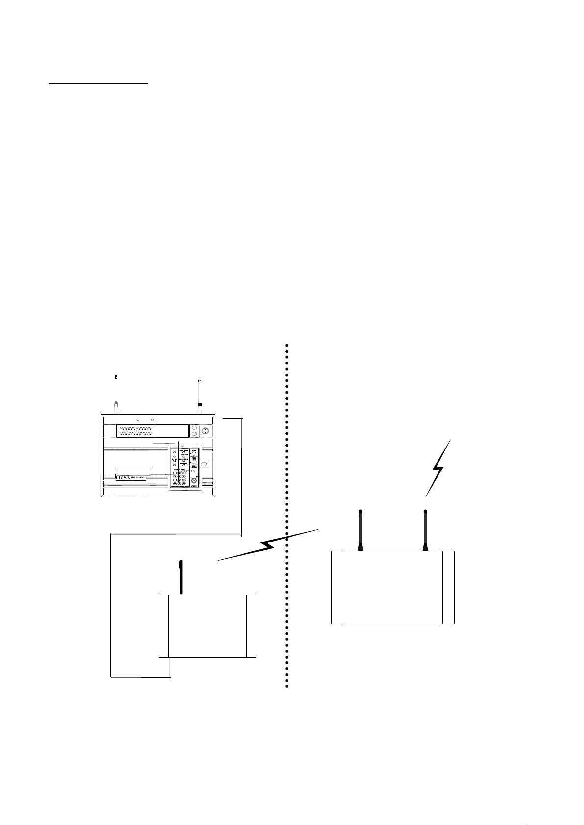
Figure 1
UHF Remote
Radio Receiver
Transponder Unit
Fire Detection
Device
Transmissions
(i.e.
Call points/
Smoke &
Heat
Detectors/
Sounders).
UHF Data
Transmitting
Aerial
VHF Data
Receiving
Aerial
UHF Data
Transmitting
Aerial
1. Introduction
The Remote Receivers used for connection to the EMS 5000 FirePoint Control Panel are
detailed in the following instructions. Two types of remote receiver can be used with the
system, both of which are hardwired to the Control Panel via 2 core screened cable.
The Model 53-5428 is a UHF remote receiver capable of receiving UHF signals from a
number of transponder units on site. The transponder units are wireless devices, which
receive information from detectors and then re-transmit this information to the UHF
remote receiver, thus improving the overall range coverage of the system. This
information is then sent to the control panel via cable (FP200). A maximum of 28 remote
receivers can be connected to the Control Panel. A block diagram of a system using the
UHF remote receiver is shown in Figure 1.
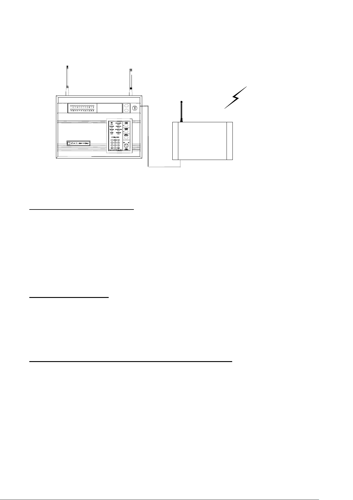
The Model 53-5414 is a VHF remote receiver capable of receiving VHF signals directly
from all types of detectors, thus improving the overall range coverage of the system.
This information is then sent to the control panel via cable (FP200). A maximum of 28
remote receivers can be connected to the Control Panel. A block diagram of a system
using the VHF remote receiver is shown in Figure 2.
©2015 EMS Security Group Ltd. All rights reserved. TSD244 Iss 3 25/06/15 AJM
Page 4
EMS 5000 FIREPOINT
4
Figure 2
VHF Remote Radio
Receiver
VHF Data
Receiving
Aerial
Fire Detection Device
Transmissions (i.e.
Call points/ Smoke &
Heat Detectors/
Sounders).
VHF Data
Receiving
Aerial
UHF Data
Transmitting
Aerial
2. Tools & Test Equipment
Only standard hand tools are required to install the Remote radio receiver system. No
special test equipment is needed when installing the receiver, although signals from
devices can be seen if a computer with a terminal programme is connected to the
system.
This gives a visual indication that the remote receivers are passing device data to the
main control panel.
3. Receiver Position
The maximum range between remote receiver and any device is dependant upon the
environment in which the system is operating. The actual range achieved is determined
by local site conditions. For range improvements high gain aerials can be attached to the
remote receivers. The table below indicates relevant aerials:-
4. UHF Remote Receiver Relevant high gain aerials
5-5501/High gain aerial c/w 3 metres of cable and bracket.
5-5501/BP10/High gain aerial c/w 10 metres of cable, wall mounting bracket and
extension pole.
5-5501/BP20/High gain aerial c/w 20 metres of low loss cable, wall mounting bracket
and extension pole.
5-5501/BP30/High gain aerial c/w 30 metres of low loss cable, wall mounting bracket
and extension pole.
©2015 EMS Security Group Ltd. All rights reserved. TSD244 Iss 3 25/06/15 AJM
Page 5

EMS 5000 FIREPOINT
5
5. VHF Remote Receiver Relevant high gain aerials
5-5500/Dipole aerial c/w 10 metres of cable and bracket.
5-5500/10 High gain external aerial c/w 10 metres of cable, wall mounting bracket and
extension pole.
5-5500/20 High gain external aerial c/w 20 metres of low loss cable, wall mounting
bracket and extension pole.
When selecting a site for the receiver, the installing engineer should be aware that the
aerial should be as far away from other electrical / electronic equipment as possible and
a minimum of 3 metres from any such equipment. Locating the receiver closer than this
will affect the systems performance. Metal objects such as filing cabinets, pipe work,
radiators and air conditioning ducts will also adversely affect the performance of the
system if they are too near the receiver antenna.
6. Electrical Installation
6.1 UHF Remote Receiver
The UHF remote receiver 53-5428, should be wired as shown in the supplied drawing
PO3045.
The following paragraphs outline the installation in a step by step format.
Remove the four lid retaining screws situated on the front cover. The front section of the
unit can now be removed.
Four fixing holes are available for the unit’s installation. These are clearly visible on the
outside of the casing.
Offer the back box up to the wall and check that the rear tamper switch operates.
Should the microswitch not operate, remove the unit from the wall and carefully adjust
the microswitch arm. Once the microswitch operates correctly the unit can be fixed to
the wall and all external wiring connections made.
The diagram PO3045 shows the wiring connections required for the remote receiver.
Only those cables needed to make the remote receiver function should be routed into
the case. The Remote Receiver must NOT be used as a junction box or cable termination
point as this will adversely affect the performance of the system.
When all connections have been made to the remote receiver the battery can be
connected, the lid can be re-fixed and mains voltage can then be applied.
©2015 EMS Security Group Ltd. All rights reserved. TSD244 Iss 3 25/06/15 AJM
Page 6

EMS 5000 FIREPOINT
6
6.2 VHF Remote Receiver
The VHF remote receiver 53-5414 should be wired as shown in the supplied drawing
P03077. The following paragraphs outline the installation in a step by step format.
Remove the four lid retaining screws situated on the front cover. The front section of the
unit can now be removed.
Four fixing holes are available for the unit’s installation. These are clearly on the outside
of the casing.
Offer the back box up to the wall and check that the rear tamper switch operates.
Should the microswitch not operate, remove the unit from the wall and carefully adjust
the microswitch arm. Once the microswitch operates correctly the unit can be fixed to
the wall and all external wiring connections made.
The diagram P03077 shows the wiring connections required for the remote receiver.
Only those cables needed to make the remote receiver function should be routed into
the case. The Remote Receiver must NOT be used as a junction box or cable termination
point as this will adversely affect the performance of the system.
When all connections have been made to the remote receiver the battery can be
connected, the lid can be re-fixed and mains voltage can then be applied.
©2015 EMS Security Group Ltd. All rights reserved. TSD244 Iss 3 25/06/15 AJM
Page 7

EMS 5000 FIREPOINT
7
Panel In Access
DATE TIME
| *** Options **** |
> Passwords <
| Time and Date |
YES = Select TIME
| * PIN’s and Access * |
>User Log On <
| View Users |
YES = Select TIME
Enter your PIN
For Access >
Then Press YES TIME
**************************
* Welcome Engineer *
**************************
Push any Key TIME
| *** Options **** |
>Passwords <
| Time and Date |
YES = Select TIME
| Logging |
>Fire System Opts <
| Remote Access |
Yes = select Time
| ** Fire system ** |
>Dev. Disable/Test <
| Net. Disable/Test |
Yes= Select Time
| System Mode |
> Engineers Config <
| Printer Options |
Yes= Select Time
| ** Eng. Config ** |
>Device Database <
| Sounder Options |
Yes= Select Time
7. Software Configuration
To allow the Control Panel and remote receivers to work together, some software
configuration will be necessary, the following instructions detail in a step by step format
how the configuration should take place for reliable communication. The menu structure
indicated at the end of this section locates the menus, which require entering.
1 With the key the “ON” position, the screen will now display:
2 Press the “0” key. The screen will now display:
3 Press the “YES” key. The screen will now display:
4 Press the “YES” key. The screen will now display:
5 Enter your PIN number (Engineering default = 221100) and
press the “YES” key. The screen will now display:
6 Press any key and the screen will display:
7 Press the “” key, until ‘the screen displays:
8 Press the “YES” button and the screen will display.
9 Press the “” key, until ‘the screen displays:
10 Press the “YES” key and the screen will display:
©2015 EMS Security Group Ltd. All rights reserved. TSD244 Iss 3 25/06/15 AJM
Page 8

EMS 5000 FIREPOINT
8
| ** Master Setup** |
>Polling Baudrate <
| Auto Re-online |
YES = Select TIME
| Reset Security |
>Reset System <
| Lan Options |
Yes= Select Time
| ** Main Menu ** |
>Pins & Access <
| System Support |
Yes= Select Time
| System Support |
> Serial Comms <
| Pager Setup |
Yes= Select Time
| ** Serial Comms ** |
>Device Table <
| Re-start Bus |
YES = Select TIME
| Re-online Device |
> Bus Master Setup <
| Bus Remote Setup |
Yes= Select Time
| Auto Re-online |
> Port to use <
| ^^^^^^^^^^^^^ |
Yes= Select Time
Master Port = 0
0 = Off, 1 = RS485
2 = PAGER 232 > _
YES = Finish TIME
| Auto Re-online |
> Port to use <
| ^^^^^^^^^^^^^ |
Yes= Select Time
| Re-online Device |
> Bus Master Setup <
| Bus Remote Setup |
Yes= Select Time
| Device Table |
>Re-start Bus <
| Re-Online Device |
YES = Select TIME
11 Press the “” key, until ‘the screen displays:
12 Press the “YES” key followed by the “0” key on the keypad
the screen will now display:
13 Press the “” key, until ‘the screen displays:
14 Press the “YES” button and the screen will display:
15 Press the “” key, until ‘the screen displays:
16 Press the “YES” button and the screen will display:
17 Press the “” key, until ‘the screen displays:
18 Press the “YES” button and the screen will display:
19 Press the “1” key followed by the “YES” key and the screen
will display:
20 Press the “NO” key once and the screen will display:
21 Press the “” key until the screen displays:
©2015 EMS Security Group Ltd. All rights reserved. TSD244 Iss 3 25/06/15 AJM
Page 9

EMS 5000 FIREPOINT
9
Re-initialising Bus
Please wait….*Done*
Push any key TIME
| Device Table |
>Re-start Bus <
| Re-Online Device |
YES = Select TIME
| Printer Redirect |
>Monitor Comms <
| Delete Device |
YES = Select TIME
HEAP00 AUX=00 PGR=00
REM000 MAS010 T00-00
I00 L00 R00 S00 C00
Push any Key TIME
| System Support |
> Serial Comms <
| Pager Setup |
Yes= Select Time
| Logging |
>Remote Rxers <
| Ext. Comms |
Yes= Select Time
|* Remote Receivers *|
>Receivers Found <
| Enable Receiver |
Yes= Select Time
| Enable Receiver |
>Enable Collector <
| Monitor Traffic |
Yes= Select Time
Collector: ENABLED
Push Yes to change
Push No to escape
Yes= Select Time
| Enable Receiver |
>Enable Collector <
| Monitor Traffic |
Yes= Select Time
Re-initialising Bus
Please wait….* *
Push any key TIME
22 Press the “YES” button and the screen will display:
23 Once completed the screen will display:
24 Push any key and the screen will display:
25 Press the “” key, until ‘the screen displays:
26 Push any key and the screen will display:
The above display can be used to check how many remote receivers are communicating
with the Control Panel. For each remote receiver that is connected, the MAS number
shown will increase by 10. I.e. if one is connected the MAS will show MAS010 if two
receivers are connected the MAS will show MAS020.
27 Press the “No” key twice. The screen will change to display:
28 Press the “” key, until ‘the screen displays:
29 Press the “YES” button and the screen will display:
30 Press the “” key, until ‘the screen displays:
31 Press the “YES” button and the screen will display:
32 The collector should be set to “ENABLED”, press the “YES”
key to change its status. Once set to “Enabled” press the
“NO” key. The screen will display:
©2015 EMS Security Group Ltd. All rights reserved. TSD244 Iss 3 25/06/15 AJM
Page 10

EMS 5000 FIREPOINT
10
| Logging |
>Remote Rxers <
| Ext. Comms |
Yes= Select Time
| Checksum Data |
> Network Router <
| Radio Lan |
Yes= Select Time
| * NETWORK ROUTER *|
>Setup local NUA <
| View network NUA |
Yes= Select Time
Local NUA :
Input Local NUA_
Yes= Finish Time
| * NETWORK ROUTER*|
> Setup local NUA <
| View network NUA |
Yes= Select Time
_ _SET AS MASTER _ _
Push Any Key Time
| Network Name |
> Control Routing <
| Send Test |
Yes= Select Time
Routing : DISABLED
Push YES to change
Push NO to escape
Yes/No Time
| Network Name |
> Control Routing <
| Send Test |
Yes= Select Time
Panel In Access
Date Time
Status Normal
Date Time
33 Press the “NO” key once and the screen will display:
34 Press the “” key, until ‘the screen displays:
35 Press the “YES” button and the screen will display:
36 Press the “YES” button and the screen will display:
37 Enter “00” followed by the “YES” key. The screen
will display:
38 Push any key and the screen will display:
39 Press the “” key, until ‘the screen displays:
40 Press the “YES” button and the screen will display:
41 The router should be set to “ENABLED”, press the “YES”
key to change its status. Once set to “Enabled” press the
“NO” key. The screen will display:
42 Press the “NO” key twice and the screen will display:
43 Now turn the control keyswitch to the “OFF” position and
the screen will display: The Remote Receiver is now
programmed to the System.
©2015 EMS Security Group Ltd. All rights reserved. TSD244 Iss 3 25/06/15 AJM
Page 11

EMS 5000 FIREPOINT
11
|**Main Menu**|
Pins & Access
System Support
Serial Comms
Pager Setup
Engineers Ctrl
Time & Date
Output Setup
Logging
Remote Rxers
Ext.Comms
Bus I/O
Fire dbase
Checksum Data
Network Router
Radio LAN
|*Serial Comms*|
Device Table
Re-Start Bus
Re-Online Device
Bus Master Setup
Bus Remote Setup
Pager 232 Redir’
Aux 232 Redirect
Printer Redirect
Monitor Comms
Delete Device
^^^^^^^^^^^^
Re-Initialising Bus
Please Wait……..
Push Any Key
|*Master Setup*|
Polling Baudrate
Auto Re-online
Port to use
|*Remote Receivers*|
Receivers Found
Enable Receiver
Enable Collector
Monitor traffic
^^^^^^^^^^^^^^
HEAP00 AUX=00
PGR=00
REM000 MAS010 T00-00
I00 L00 R00 S00 C00
Master Port =1
0=Off, 1 = RS485
2=PAGER 232
Enabled
Push YES to change
Push NO to escape
Push YES/NO TIME
Enabled
Push YES to change
Push NO to escape
Push YES/NO TIME
Local NUA : 00
Input Local NUA
YES = Finish TIME
|*Network Router*|
Setup local NUA
View Network NUA
Network Name
Control Routing
Send Test
8. Main Control Panel Engineers Menu Structure
©2015 EMS Security Group Ltd. All rights reserved. TSD244 Iss 3 25/06/15 AJM
Figure 3
Page 12

EMS 5000 FIREPOINT
12
9. Testing The System
If the system is not performing as expected in terms of range, monitoring the Comms
between the main and remote receivers may well indicate the cause of the problem (see
Figure 3).
For example, a large number of Time-outs by a particular remote indicates a poor
connection, poor screening, or the cable passing near enough to a data cable to
introduce interference onto the bus.
Once VHF Remote units have been installed and are communicating with the Control
Panel, devices should now be tested from their fixed positions.
Once UHF Remote units have been installed and are communicating with the Control
Panel, the transponder units which will send device information to the remote receiver
should be installed (see transponder installation instructions for details).
©2015 EMS Security Group Ltd. All rights reserved. TSD244 Iss 3 25/06/15 AJM
Page 13

EMS 5000 FIREPOINT
13
©2015 EMS Security Group Ltd. All rights reserved. TSD244 Iss 3 25/06/15 AJM
Page 14

EMS 5000 FIREPOINT
14
©2015 EMS Security Group Ltd. All rights reserved. TSD244 Iss 3 25/06/15 AJM
Page 15

EMS 5000 FIREPOINT
15
Dimensions:
390mm x 320mm x 80mm
Operating Frequencies:
UHF 458.5 – 459.5 MHz (Receiver)
Operating Temperature:
-10 to +55 degrees C
Humidity:
Up to 75% non-condensing.
Channel Spacing:
25 kHz
Supply:
230v 50Hz
Current Consumption:
154mA in standby
Battery space:
1 x 12volt 7Ah batteries (supplied)
EMS only recommend: Yucel Model No: NP712 or a battery of equivalent specification
Recommended battery
replacement intervals:
5 years
Dimensions:
390mm x 320mm x 80mm
Operating Frequencies:
VHF 173.2 – 173.5 MHz (Receiver)
Operating Temperature:
-10 to +55 degrees C
Humidity:
Up to 75% non-condensing.
Channel Spacing:
25 kHz
Supply:
230v 50Hz
Current Consumption:
154mA in standby
Battery space:
1 x 12volt 7Ah batteries (supplied)
EMS only recommend: Yucel Model No: NP712 or a battery of equivalent specification
Recommended battery
replacement intervals:
5 years
10. Controller Information
TECHNICAL INFORMATION FOR THE UHF Remote Receiver
TECHNICAL INFORMATION FOR THE VHF Remote Receiver
©2015 EMS Security Group Ltd. All rights reserved. TSD244 Iss 3 25/06/15 AJM
Page 16

EMS 5000 FIREPOINT
16
©2015 EMS Security Group Ltd. All rights reserved. TSD244 Iss 3 25/06/15 AJM
 Loading...