

Page 1

COMBINED SOUNDER / SENSOR
INSTALLATION MANUAL
MK235 Iss 4 20/12/2016 AJM
Page 2
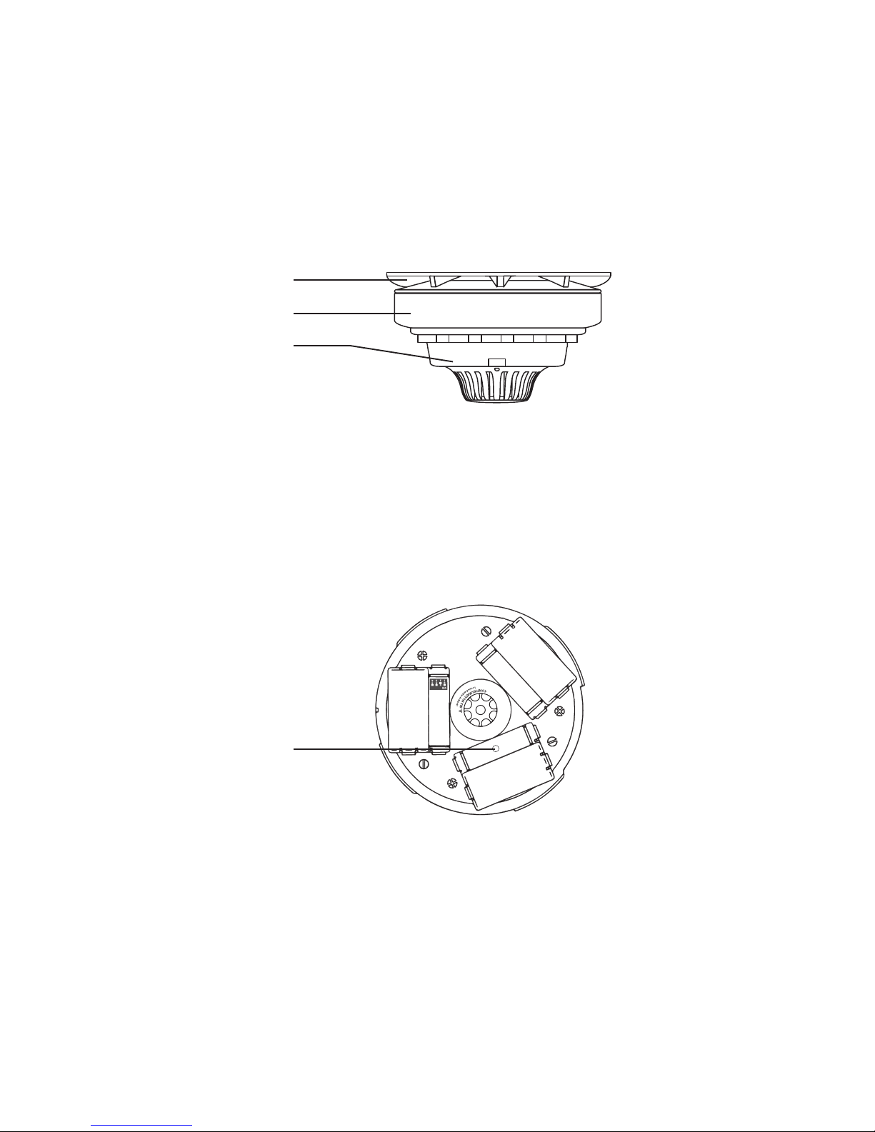
Figure 2
Logging the device to the system
If the installation has been ordered as a complete system the devices and panel will be supplied already
“pre-programmed”. The process of adding radio devices (Callpoints, Detectors, Sounders, Input / Output
Units and Transponders) to the System 5000 Control Panel, is largely carried out automatically, by the
Panel’s own operating system. It is usual practice for each device to require “logging on” to the system.
In such cases, the following action must be taken.
The sounder sensor is shown below in Figure 1 and consists of three separate sections.
The wireless module can be programmed to the system by the following procedure:
1 - Remove the mounting plate by turning it counter clockwise.
2 - Ensure the “Logging On” function on the control panel is enabled. Refer to the ‘Engineers Operating
Guide’ for full details.
3 - Ensure all but one batteries are tted, leaving out the one that covers the log on button - as shown
in Figure 2.
Mounting plate
Wireless module
Sensor
Figure 1
Log on button
4 - Press the log on button for 3 seconds. The message ‘Log On Default Device XXX’ (Where XXX is the
device’s address number on the system) will be displayed on the control panel’s front display.
5 - After a short time the message ‘Added Default Device XXX’ will be displayed on the control panel’s
front display.
6 - After approximately 10 seconds ‘New Head Default Device XXX’ will be displayed on the control
panel’s front display.
7 - Once complete, disable the control panel’s log on feature. Refer to the ‘Engineers Operating Guide’
for full details.
Figure 2
MK235 Iss 4 20/12/2016 AJM
Page 3

Setting Sensitivity
The device is able to detect either smoke or heat by simply changing the sensor’s switch conguration.
This allows easy interchanging between heat and smoke modes without having to purchase a new
sensor. The sensitivity switch location is shown in Figure 3.
OFF ON
L946-5
Placed on the market by
UTC Fire & Security.
Part no. 68701. See
Installation Sheet 1631.
ZR432-2 Radio Multisensor (Optical/Heat) Detector
FCZ-174-001
EN54-7
EN54-5 Class A 1
Made in South Africa
0359-CPD-0112
SENSITIVITY
LOW
LOW
+AVF
MED
HIGH
OFF
ON
2
1
L744-4
ON
1 2 3 4 5 6 7
OFF ON
L946-5
SENSITIVITY
LOW
LOW
+AVF
MED
HIGH
OFF
ON
2
1
L744-4
ON
1 2 3 4 5 6 7
Figure 3
Figures 4 & 5 illustrate the dip switch settings to accomplish the required function from the sensor.
Smoke Sensitivity Settings
Sw 1 Sw 2 Sw 3 Sw 4 Sw 5 Sw 6 Sw 7 Mode of Operation
Smoke Sensitivity %
Per M
Off
Off
Off
On
Off X On
High Sensitivity
1.6
Off
On
Off
On
Off X On
Normal Sensitivity
2.3
On
Off
Off
On
Off X On
Low Sensitivity
3.0
On
On
Off
On
Off X On
Low Sensitivity + AVF
3.0 + AVF
Figure 4
Heat Sensitivity Settings
Sw 1 Sw 2 Sw 3 Sw 4 Sw 5 Sw 6 Sw 7 Mode of Operation
Off
Off
Off
Off
On X On
58°C ROR
Off
On
Off
Off
On X On
58°C fixed
On
Off
Off
Off
On X On
75°C fixed
On
On
Off
Off
On X On
82°C fixed
Figure 5X – Not Used
ROR – Rate of Rise
AVF - Accelerated Alarm Verication, to prevent false alarms due to transient smoke.
Please Note
The nal commissioning, detection sensitivity settings and hand over of the re system to the end user
is the responsibility of the re installation contractor.
MK235 Iss 4 20/12/2016 AJM
Page 4

Figure 2
Conguration Switch Settings
The device is dispatched with conguration switches set as per Figure 6.
Figure 6
Switch 1: Tamper = disabled
Switch 2: Self sound = disabled
Switches 3/4: Volume = high
Tamper Disablement Feature
The device has a tilt operated tamper switch for removal detection. This feature can be enabled or
disabled using Switch 1.
Putting switch 1 to the ON position will disable the devices’s tamper monitoring.
Self Sound Feature
The device has the ability to sound immediately upon entering an alarm condition, when the re panel
is used in visual delay mode. It is therefore possible for an individual area to be alerted without
evacuating the whole building.
To enable the self-sounding option, switch 2 must be in the ON position.
Sounder Volume
The device’s sounder volume can be adjusted using the switches 3 and 4. The switch settings for the
volume are shown in gure 7.
High
Medium
Low
Switch
settings
3 & 4 On
3 Off 4 On
3 & 4 Off
Figure 7
MK235 Iss 4 20/12/2016 AJM
Page 5

Optional device locking
It is possible to lock the sensor into the wireless base. Locking is made possible by removing the cut out
section as shown in Figure 8.
Figure 8
Cut out section
(shaded area)
To remove the sensor once locked, insert a at blade screw driver into the lock release slot (shown in
Figure 9) and push the screw driver down into the device to release the mechanism. The sensor should
unlock and can now be removed by turning it anticlockwise.
Lock release slot
LED position
Figure 9
Additional locking of the wireless module into the xed mounting plate can be achieved by tting an
anti tamper screw. A 5/16 Phillips pan head screw is supplied within the packaging of each unit. To t
the anti tamper screw, the tamper knockout must be removed. The location of the tamper knockout is
shown in Figure 10.
Figure 10
Tamper knockout
MK235 Iss 4 20/12/2016 AJM
Page 6

www.emsgroup.co.uk
Third Party Accredited
ISO 9001 ISO 13485 ISO 14001
The information contained within this literature is correct at time of publishing. The EMS Security Group Ltd reserves the right to change any infomation regarding products as
part of its continual development enhancing new technology and reliability. The EMS Group advises that any product literature issue numbers are checked with its head oce
prior to any formal specication being written.
 Loading...