

Page 1

ON -WALL SP EAKERS
Model
EW25
Model
EW30
Model
EW35
US ER & I NSTA LL ATI ON M AN UAL
Page 2
Introduction
Congratulations on your purchase of an EMP Tek EW25, 30 or 35 on-wall
Speaker! Your speaker is the result of many years of research and development
dedicated to producing powerful, high-quality home audio systems.
is manual contains setup recommendations and specications for the
EW25, EW30 and EW35 on-wall speakers. It is recommend you thoroughly
read through the material contained in this manual before connecting your
speakers. is will ensure you have an understanding of how to properly setup
and operate your speakers for optimum performance.
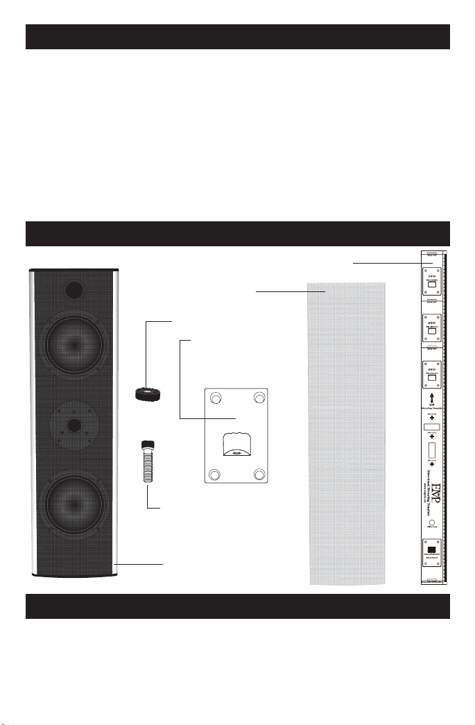
EW On-wall Speaker Contents
Directional Mounting Template (DMT)
Silver Grille
(1) Damping Spacer
(2) Mounting Brackets
with (8) drywall
anchors and
(8) screws
(2) Hex Bolts
EW On-wall Speaker
with Black Grille Installed
Break In Period
Allow 18-24 hours of listening time to adequately allow the EW series speakers to break-in. During this rst 18-24 hour listening period, the driver’s
suspensions will loosen, resulting in an increase in low frequency response,
improved denition, and increased clarity and detail.
1
Page 3

Care and Cleaning
To maintain the speaker’s high quality appearance, it is recommended to
regularly use a dry or slightly-damp so cloth to keep the exterior free from dust
or dirt. To clean dust from the grille, use a vacuum with a brush attachment.
Features
e EW series was designed to be mounted directly onto a wall, and coordinate
with at panel displays. ese speakers may be used for stereo, or can be
used in surround sound applications such as le and right front channels,
dedicated center channel, and as surround channels. e composite woofer
cone, fabricated from cellulose acetate pulp impregnated with mica substrate
and damped with carbon ber/resin polymer has a very high ratio of weight to
rigidity, permitting the EW series on-wall to deliver thundering bass response
in combination with breathtaking vocal clarity.
For high frequencies, a premium quality silk/polymer resin dome tweeter is
used. is tweeter uses a special magnetic liquid cooling to protect the tweeter
from damage and allow greater power handling.
e EW series specialized crossover design allows the speaker to be used
horizontally or vertically. e crossover system enables at frequency response
with either placement.
The EW series’ sealed cabinet, constructed from extruded aluminum,
eliminates midrange resonances, and the narrow prole minimizes cabinet
diraction. e speakers virtually disappear, leaving only a deep, wide sound
stage with pinpoint imaging.
System Setup
In order to extract the best possible sound from your speaker system, it is
important to determine where the speakers will sound best in your listening
room. Room reections from the oor, ceiling and side walls will inuence
the balance, imaging and overall sonic quality of the listening experience. It
is suggested you experiment with dierent speaker placement possibilities to
determine which location oers the best overall sound. Since the EW series
is designed to be installed next to at-panel televisions or displays such as
plasma and LCD monitors, this may dictate placing the speakers on each side
of the television, and either above or below if used as a center channel.
2
Page 4

System Setup
EW25/EW30/EW35
Bite Direction
e EW series speaker is designed to sound best when placed with its back
against a wall, using the supplied mounting brackets. ese brackets allow the
speaker to pivot or be angled towards the listening position, which may provide
a more spacious and realistic sound stage. Optimal imaging and performance
is achieved when the measurement from the oor to the middle of the EW
series on-wall speaker is between 39-45 inches; however, the location of the
television or display may not allow this placement.
For optimal performance in surround sound applications, the main front le
and right channel speakers should be mounted on either side of the television
or display with the television generally centered between the speakers. e
center channel speaker should be centered above or below the television.
Surround channel speakers should be placed behind and, or to the sides of, the
listening position. e listening position is typically centered in-between the
surround speakers. Try experimenting with the surround channel speakers
by angling them slightly towards or away from the listening position. is
angle can have a dramatic eect on the surround channel’s performance as
well as the overall surround sound experience.
Installation – Mounting Brackets
Use the enclosed Directional Mounting Template or DMT (see illustration
on page 1) to determine and mark your desired speaker location. e DMT
features bubble-type levels to help you install the speaker as level (horizontal)
or plumb (vertical) as possible. Place the DMT where the speaker will be
installed and pay close attention to center the DMT for the EW series model
you’re installing. For example, if you’re installing an EW30, make sure to
use the EW30 centering cross hair marks on the DMT and not the EW25
or EW35 centering cross hairs. Use a pencil to mark the four mounting
holes for the lower bracket, and then mark the four mounting holes for the
Directional
Mounting
Template
(DMT)
Mounting Holes
Bite direction shown here
on back plate facing down.
Mounting Holes
3
Page 5

Installation – Mounting Brackets
upper bracket located at the other end of the DMT. Again, pay close attention
to mark the correct mounting holes for the model you’re installing.
NOTE: Ultimately, the wall location where you’ll be installing your EW series
speaker will have a stud or other framing member very close by. You may
want to use a stud-nder (available at your local hardware store) to locate the
nearest stud. It is highly recommended you place your EW series mounting
brackets where at least two of the bracket’s screws can be placed into a stud
or other framing member. en, follow the drywall mounting steps below
for the other two remaining holes per mounting bracket. Mounting your EW
series speaker this way provides for a very secure installation.
If the wall location doesn’t have a stud or other framing member nearby,
and you need to install your mounting brackets onto drywall only, use a
screwdriver or drill-driver to screw a zinc drywall anchor (see the illustration
below) into each of the eight mounting bracket hole locations you’ve marked.
e drywall anchors have a self-drilling end which does not require you to
pre-drill the hole.
Screw the Four Anchors into
Marked Mounting Holes
Fasten Bracket to Wall
with Four Screws
Mark Mounting Holes
using the DMT
Once all drywall anchors are in place, place the mounting bracket in position,
paying careful attention to the bite direction of the bracket (see illustration
on page 5). e bite direction of both brackets faces outward from the center
of the speaker. Use a screwdriver or drill-driver and four screws per mount
to fasten each bracket to the wall securely.
If mounting to surfaces other than drywall, we recommend you consult
with a hardware or construction professional to obtain the best hardware
for your application.
4
Page 6

Attaching Speaker Wires
Remove the round terminal nuts from the terminal posts on the back of the
speaker. Remove 1/4” to 3/8” of the insulation from the end of each speaker
wire. Insert the ends of the speaker wires into each terminal making sure to
observe proper polarity (typically, the positive wire is red, and the negative
wire is black). Verify the wires are in the correct terminal holes and replace
the terminal nuts. Tighten each nut so the wire is securely attached.
Speaker Wires
Back View of Speaker
Mounting Speakers
To mount the speaker to the mounting plates on
the wall: 1.) Place the damping spacer on top of the
speaker’s lower mounting bracket as shown in the
illustration to the right; 2.) Line up the speaker’s
lower bracket to the lower wall mount bracket;
3.) Insert one hex bolt into the bottom hole on the
speaker’s mounting bracket and into the lower wall
bracket; 4.) Line up the speaker’s upper bracket
with the upper mounting bracket as shown in the
illustration below; 5.) Insert the other hex bolt
into the top hole on the
speaker’s upper mounting bracket and into the
upper wall bracket. e speaker should now be able
to pivot on both brackets. 6.) Use the included hex
wrench to tighten both hex bolts until the speaker
cannot pivot and is securely attached to both
brackets. Adjusting the pivot angle of the speaker
is as easy as loosening the two hex bolts, adjusting
the angle of the speaker, then tightening the bolts
to lock the speaker at the desired pivot angle.
5
Terminal
Posts
Terminal
Nuts
Page 7

Changing e Grille
Your EW series on-wall speaker comes with
a black grille, but an optional silver grille is
included. Select the grille which best matches
your décor. If you wish to change the grille,
follow these steps:
To remove the grille:
1.) Use the smaller hex key tool to remove
the four hex bolts from both end caps of the
speaker;
2.) Remove both end caps;
3.) Firmly grasp both ends of one side of the
grille to gently ex and li the grille out of the
recessed track.;
4.) Gently pull the other side of the grille from
its recessed track.
To re-insert grille:
1.) Insert one side of the grille into the recessed
track on one side;
2.) Firmly grasp both ends of the opposite side
of the grille and gently ex and insert the grille
into the opposite recessed track;
3.) Make sure the grille is centered in the speaker,
and place one end cap onto the speaker;
4.) Place 4 hex head screws through the end
cap and into the speaker and tighten using the
smaller hex wrench;
5.) Repeat step 4 for the opposite end cap.
6
Page 8

Specications
Model EW25 EW30 EW35
Frequency
Response:
Sensitivity: 86dB (2.83V@1m) 86dB (2.83V@1m) 86dB (2.83V@1m)
Power
Handling:
Woofer: (2) 5½” Pulp Mica
Tweeter: 1” Silk/Poly Dome 1” Silk/Poly Dome 1” Silk/Poly Dome
Impedance: 6 Ohms 6 Ohms 6 Ohms
Crossover
Frequencies:
Dimensions: Height: 25”
Grille: Black or Silver
Finish: Silver and Black End
Weight:
48Hz – 20kHz ±3dB 45Hz – 20kHz ±3dB 42Hz – 20kHz ±3dB
50-200 Watts 50-200 Watts 50-200 Watts
Carbon Fiber
Composite
(2) 5½” Pulp Mica
Carbon Fiber
Composite
(2) 5½” Pulp Mica
Carbon Fiber
Composite
220Hz / 2.2kHz 220Hz / 2.2kHz 220Hz / 2.2kHz
Height: 30”
1
Width: 7 ”
5
Depth: 5 ”
8
8
1
Width: 7 ”
5
Depth: 5 ”
8
8
Black or Silver
(Both Included)
(Both Included)
Silver and Black End
Caps with Black
Accents
16½ lbs. 19½ lbs. 23 lbs.
Caps with Black
Accents
Height: 35”
1
Width: 7 ”
Depth: 5 ”
8
5
8
Black or Silver
(Both Included)
Silver and Black End
Caps with Black Accents
7
Page 9

Warranty
Your EW series on-wall speakers are covered by a limited warranty against
defects in materials and workmanship for a period of 5 years from the
original date of purchase. is warranty is provided by the authorized
EMP Tek dealer where the speaker was purchased. Warranty repair will
be performed only when your purchase receipt is presented as proof of
ownership and date of purchase. Defective parts will be repaired or replaced
without charge by your dealer’s store or the location designated by your
dealer authorized to service EMP Tek products. Charges for unauthorized
service and transportation cost are not reimbursable under this warranty.
is warranty becomes void if the product has been damaged by alteration,
misuse or neglect. e warrantor assumes no liability for property damage or
any other incidental or consequential damage whatsoever which may result
from the failure of this product. Any and all warranties of merchantability
and tness implied by law are limited to the duration of this express warranty.
Some states do not allow limitations on how long an implied warranty lasts,
so the above limitations may not apply to you. Some states do not allow the
exclusion or limitation of incidental or consequential damages, so the above
limitation or exclusion may not apply to you.
8
Page 10

382 Marshall Way, Layton, Utah • USA • 84041
Toll Free: (800) 543-2205 • Fax: (801) 543-3300
www.emptek.net
It is EMP Tek policy to contin uously incor porate improvements into prod ucts; all speci cations ar e subject to chang e without notic e.
Copyright © 20 07 EMP Tek. All Rights Re served.
 Loading...