

Page 1
BE RY L LI U M C O N E SPE A K E RS
Model
41-SE/B
BERYLLIUM CON E SPEAKERS
OW N E R ’S M A N UA L
Page 2
Introduction
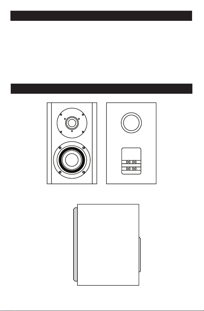
FRONT VIEW
BACK VIEW
SIDE VIEW
Congratulations on your purchase of EMP Tek 41-SE/B speakers! Your speakers are the
result of many years of research and development dedicated to producing high quality
products for home audio systems.
is manual contains features, setup recommendations and specications for the
EMP Tek 41-SE/B speakers. We recommend you thoroughly read through the material
contained in this manual before connecting your speakers. is will ensure you have
a good understanding of how to setup your speakers for optimum performance and
allow for years of listening enjoyment.
41-SE/B Bookshelf Speakers
2
Page 3

Break-in Period
Allow several hours of listening time to adequately break-in the speakers. As the speakers
break-in, the driver suspension will loosen. e result of break-in will be an increase in
low frequency response, improved denition, and increased clarity and detail.
Care and Cleaning
To maintain speaker appearance, we recommend wiping them down with a clean
and damp, so cloth. To clean dust from the grille cloth, use a vacuum with a brush
attachment.
Features
At the heart of the EMP Tek 41-SE/B speakers are proprietary beryllium cone woofers.
e special beryllium cone material combines stiness, low mass and self damping
properties in a manner that allows virtually uncolored presentation of program
material. A powerful magnet, extended voice coil and bumped back plate give the
bass/midrange drivers high excursion capability. is ensures accurate dynamic
reproduction. For high frequencies, a premium quality silk dome tweeter is used.
is tweeter uses liquid cooling to allow greater power handling.
Each EMP Tek speaker features an extensive crossover network. Steep acoustic slope
crossovers are used to integrate drivers. e use of steep crossover slopes allows for
higher power handling, minimizes driver interaction anomalies, and maximizes the
ability of each driver in their respective band of frequencies. Large 5-way binding posts
ensure a good, solid electrical connection to these crossover networks.
EMP Tek 41-SE/B spea ker cabinets are constr ucted of ¾-inch medium density berboard because of its inert properties, thereby preventing sound coloration
due to cabinet diffr act ion. The thickness of the front baff les als o prevents
excess acoustic radiation. Sophisticated computer modeling and measurement
techniques are used extensively throughout the EMP Tek speaker design process.
Attaching Speaker Wires
When using a banana jack to attach speaker wires to the binding post terminals, insert
the speaker wire into the banana jack. Next insert the banana jack into the hole provided
in the top of the terminal. Be sure the nut is tight before inserting the banana jack. Repeat
for the other speaker wire(s) as necessary, see diagram on page 4.
If not using a banana jack, simply loosen the binding nut to allow the hole in the side
of the terminal to become exposed. Strip ¼-inch of the insulation from the end of the
speaker wire and insert the exposed wire end into the now exposed hole in the side of the
terminal. Tighten the binding nut by turning the nut clockwise until the speaker wire is
secured. Repeat for the other speaker wire(s) as necessary, see diagram on page 4.
3
Page 4

Attaching Speaker Wires (continued)
Room Setup Suggestions
In order to obtain the best possible sound from your speaker system, it is important
to determine where the speakers will sound best in your listening room. Room
reections from the oor, ceiling and side walls inuence the balance, imaging and
overall sonic quality at the listening position. Experiment with speaker placement to
determine which location oers the best overall sound. As a general guide, use the
room layout diagram and following the descriptions when setting up a home theater
system. Some speakers shown in the diagram on the next page may not be applicable
to your individual system.
Front Main Speakers
As a starting point, place your le and right front speakers at least 15 inches from
the wall and 7 feet apart from each other. e distance from the listening position
to each speaker should be close to the distance that separates the two main speakers.
Angling the speakers inward towards the listening position may give a more spacious
and realistic sound stage. Main speakers may be placed on stands to place the tweeters
closer to ear height.
Center Channel Speaker
e Center Channel Speaker should be placed between both le and right main
speakers. Oen this positioning dictates placing the speaker either directly above or
below a television monitor. Since some speakers are available with video shielding,
the center speaker may be placed in close proximity to a CRT-type television without
cause for concern.
Rear Surround Speakers
e Surround Speakers may be placed either above, behind or to the sides of the listening
position. e listening position should be centered between the surround speakers.
4
Page 5

Room Setup Suggestions (continued)
Rear Surround Speakers (continued)
For best performance, you may want to experiment with angling the surround speakers either
towards or away from the listening position.
Subwoofer
Placement of the subwoofer will largely determine quality, quantity, and extension of
the bass frequencies within your listening room. Bass frequencies are reinforced by
close room boundaries. Placing the subwoofer in a corner will make the subwoofer
sound louder and boost the very lowest frequencies. Placing the subwoofer away from
walls will provide the least reinforcement, making the bass sound subjectively thinner.
Good results can usually be obtained by placing a subwoofer along a wall 1-3 feet from
a corner. Experiment with subwoofer placement and the sub-amplier controls to
achieve the proper bass balance.
5
Page 6

Specications
Model 41-SE /B
Speaker Type
Frequency Response:
Sensitivity:
Recommended Power:
Woofer:
Tweeter:
Impedance:
Crossover Frequencies:
Crossover:
Dimensions:
Grille Color:
Finish:
Weight:
Bookshelf 2-way Bass Reex
60Hz – 20kHz ±3dB
88dB (2.83V @ 1M)
30-100 Watts
(1) 4” (102mm) Beryllium Cone
(1) 1” (25mm) Silk Dome
8 Ohm
3,000 Hz
12dB/Octave
Width: 6-3/4” (171mm)
Height: 11-1/2” (292mm)
Depth: 10-1/4” (260mm)
Black Fabric
Black Oak Wood Grain with Gloss Black Tops and Bottoms
12 lbs. (5.44 Kg)
Troubleshooting
Situ ation:
No sound from
speakers
No sound from
one speaker
Very little bass
and/or imaging
Probable C ause:
Speaker wire not connected
Speaker selector on amplifier is
not on
Balance control on receiver
or pre-amp is not centered
Speaker wire not securely
connected
Speakers are wired out of phase
6
Solut ion :
Make sure wire is connected
at both the speaker and the
amplifier observing proper
polarity
Activate proper selector on
amplifier
Place balance control in the
center
Check all connections at
amplifier and speakers
Check entire system for proper
polarity and make adjustments
as necessary
Page 7

Warranty
Engineered Music Products “EMP Tek” warrants all EMP speakers and subwoofers
against defects in materials and workmanship for a period of 5 (ve) years on the
woofer and cabinet, and 1 (one) year on the amplier from the original date of purchase
from an authorized EMP Tek reseller or the EMP Tek web site www.emptek.com. is
warranty extends only to the original purchase. EMP Tek does not warrant goods used
in industrial applications. is warranty does not cover any expenses incurred in any
removal or re-installation of the product.
If the product should prove defective within the warranty period, contact EMP Tek
for a return authorization number prior to returning the product by prepaid delivery
to EMP Tek, along with the original sales invoice or other proof of purchase, which
establishes eligibility for warranty service. EMP Tek will, at its option, replace or repair
the product free of charge and return the product by prepaid delivery. is warranty
does not apply to any product which has been damaged, misused, altered, neglected or
repaired by anyone other than an EMP Tek authorized service facility.
Any implied warranties including tness for use and merchantability are limited in
duration to the period of the express warranties set forth above, and no person is
authorized to assume for EMP Tek any other liability in connection with the sale of
the product. EMP Tek expressly disclaims liability for any incidental and consequential
damages caused by the product or the result of failure of this product. e remedies
provided under this warranty are exclusive and in lieu of all others.
is warranty gives specic legal rights. In addition, there may be other legal rights
arising from the sale of the product, which vary from state to state. Some states do not
allow the exclusion or limitation of incidental or consequential damages, so the above
limitation or exclusion may not apply in some areas.
Extended warranty available at www.emptek.com/extendwarranty.php
7
Page 8

382 Marshall Way, Layton, Utah • USA • 84041
Toll Free: (801) 991-1308 • Fax: (801) 543-3300
www.emptek.com
It is EMP Tek policy to contin uously incor porate improvements into produ cts; all speci cations are su bject to change wi thout notice.
Copyright © 20 09 EMP Tek. All Rights Reserved.
 Loading...