

Page 1
phaser
user manual
Page 2

Introduction
The Empress Phaser was designed to give you maximum control in a
small, manageable package. We’ve combined features that will
enable you to realize all your phasing dreams.
You’ll recognize the tap feature from our other pedals. And, with
the Empress Phaser, we’ve also introduced the universal control
port. Now you can control your phaser from a control voltage (CV),
an expression pedal, an external audio input, external tap switch, or
via MIDI.
Under the hood we’ve included a couple switches which allow you
to change the pedal’s configuration. There’s a switch to enable a
vibrato mode and a switch that adds some pleasing harmonics to
the signal if clean and pristine isn’t your thing.
To help you get the most out of this product, we’ve put up some
brief instructional videos on our website:
www.empresseffects.com
Page 3

Quick Start
Set the knobs and switches to match the picture above. If the blue
bypass LED is not already lit, press the bypass switch to engage the
phaser.
Page 4

Operating Modes
The phaser has three modes: knob mode, tap mode and auto mode.
Knob mode: The speed of the phaser is set with the speed knob and
the speed range switch. The fastest speed range will give you ring
modulator type sounds.
Tap mode: The speed is set by tapping in a tempo with the tap
stomp switch. The speed of the effect will be the tapped tempo,
multiplied by the ratio set using the ratio knob. For example, if you
set the ratio knob at 1:2, the speed of the phaser will be twice as
fast as the tempo tapped.
Auto mode: In auto mode, the effect parameters are changed based
on how you are playing. We’ve set out an entire section in this
manual to explain this very cool and deep mode. You will also find a
handy reference chart printed on the front of the pedal.
Page 5

Auto Mode
In auto mode, the effect parameters are changed based on how you
are playing. The changes follow the envelope of the input signal, or
are triggered by sudden changes in the signal volume.
Effects parameters are changed in one of two ways when you use
auto mode:
1. Envelope Follower
When following an envelope in auto mode, the pedal tracks
the input volume and changes a parameter to follow the
changes in the volume level. The envelope follow approach
is used in submodes 1 through 4.
2. Trigger Detection
When detecting a trigger in auto mode, the pedal tracks the
signal and when a sudden, rapid increase in volume occurs,
it changes the parameter from a low to high value. The kind
of actions that would set off a trigger might be an
aggressive strum on a guitar or a chord hit on a Rhodes. The
trigger detection approach is used in submodes 5 and 6.
Page 6

The Attack and Release Controls
In submodes 1 through 4, the attack switch determines how quickly
the pedal reacts to an increase in input signal volume.
For example, with submode 2 selected and the attack set to fast, a
sudden increase in volume will increase the phaser rate almost
instantly. With the attack set to slow, it takes much longer for the
speed of the effect to increase.
The release knob controls how quickly the pedal reacts to a
decrease in input signal volume. Set fully counter-clockwise the
release time is the fastest. Set fully clockwise the release time is the
slowest.
A slower release time generally sounds a bit smoother and a faster
release time, more abrupt and jarring.
In submodes 5 and 6, the attack switch sets the speed at which the
parameter moves from its minimum to maximum value. The release
knob sets the speed at which the parameter returns back to its
starting value.
Page 7

Sensitivity
The sensitivity knob controls how the pedal listens to your input
signal when in auto mode. For softer input signals you should set
the sensitivity to a higher value. For louder input signals it should be
turned down.
In an auto mode that uses trigger detection, the red LED above the
tap switch indicates that a trigger has been detected. If you find the
auto mode is missing some of the triggers, increase the sensitivity. If
you find the auto mode is triggering when it shouldn’t be, decrease
the sensitivity.
When the pedal is in a submode that uses envelope detection the
red LED above the tap switch will light up when it is detecting
maximum volume. Ideally, in envelope based submodes, the LED
will only light up when you’re playing your absolute loudest. This
will ensure you are experiencing the full range of parameter sweep.
Setting the expression switch to ‘speed’ will allow you to control the
sensitivity with an expression pedal.
Page 8

The Submodes
There are eight submodes available in auto mode.
Submode 1: Phase Shift Follows Envelope
The center of the phase shift changes according to how loud
you play. Hitting the tap switch inverts the phasing motion
for a different tone.
Submode 2: LFO On Envelope
The speed and the center of the phasing effect are both
increased as the input signal grows louder. The tap switch
reverses the changes as the signal grow louder.
Submode 3: Speed Follows Envelope (Sine Waveform)
As the instrument signal gets louder the speed of the
phasing effect increases. The waveform selected for this
mode is a sine wave with a width of 50%. Press the tap
switch to have the speed slow down as the instrument
volume increases.
Try the attack and release set fast so that the envelope
tracking is very tight. The sensitivity controls the fastest
speed that will be reached when the signal is loudest.
Page 9

Submode 4: Speed Follows Envelope (Random Waveform)
Similar to submode 3 except it uses a random step
waveform. The louder the input signal the more frequently
a new speed value is chosen at random for the effect.
Hitting the tap switch reverses the action so that a louder
signal causes the waveform to slow down.
Submode 5: Follow Trigger
A peak in the volume of the input signal will trigger the
effect to shift from maximum phasing to minimum phasing.
Hitting the tap switch inverts the phasing motion for a
different tone. The LED above the tap switch turns red
when a trigger is detected.
Submode 6: Trigger Random Level
When a trigger is detected the amount of phase is shifted
to a new, random amount. This mode sounds close to a
random waveform, but the changes can be controlled and
triggered by how loud you play your instrument. In this
mode, the release knob determines how quickly it shifts
from the current random level to the next. The attack
toggle has no effect.
Page 10

Submode 7: Rhythm Mode
Ratio
Knob
Time
Signature
Rhythm
1:1
3/4
2:3
2/4
1:2
5/4
1:3
6/8
1:4
4/4
Cycle through preset rhythm patterns by turning the ratio
knob. Each ratio represents a different pattern. You can
change the speed of the rhythm pattern by hitting the tap
stomp switch. There are five different rhythms available for
you to explore. The release knob determines how quickly it
shifts from the current random level to the next random
level in the rhythm. Here are the different patterns:
Page 11

Submode 8: Direct Control Mode
Without an expression pedal plugged in to the control port,
this mode operates like submode 5, except that it triggers
only when you hit the tap stomp switch. Hold down the tap
switch and the sweep will keep rising to its maximum
value. Release the tap switch and the sweep will return to
its starting value.
If you plug an expression pedal into the control port, this
submode will allow you to control the degree of phase
shift with the expression pedal. The speed knob, width
knob, and expression switch are ignored in this mode.
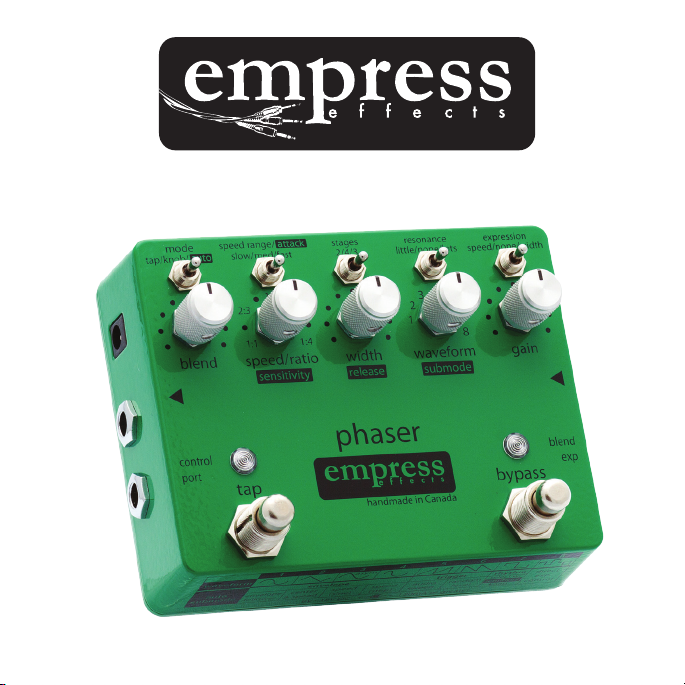
Page 12

stages: selects the number of all-pass poles. The
2-pole setting sounds the least eected, 4-pole is
the setting you’ll nd in most one-knob phasers, and
3-pole sounds quite dierent from both
speed range: controls the range of speeds available
on the speed/ratio knob
mode: set to control the speed with either tap or
knob. Select auto mode to use the audio input to
control the phaser dynamically
blend: controls the mix between the original signal
and the phase-shifted signal. Fully clockwise will
result in the deepest phase cancellations
speed/ratio: with the mode switch set to tap, this knob
sets the multiplication ratio for the tapped tempo.
With mode set to knob, this controls the speed of the
phaser
tap stompswitch: use to set the speed of the phaser.
Tempo will be multiplied by the current setting on the
ratio knob
Controls at a Glance
+
power: 9V - 18V DC negative
tip 2.1mm jack. 120mA or greater
-
* these controls are for tap and knob modes. Auto mode uses the controls marked with inverted text. These are outlined in the auto mode section
Page 13

resonance: selects the amount of feedback applied,
creating resonant peaks in between valleys
expression: selects which knob the expression pedal
will control via the control port
gain: controls the output gain. The point where unity
gain lies depends on the pedal’s other settings
waveform: selects between 8 dierent waveforms
asym
width: determines how far the phase shift varies
from the center position
bypass stompswitch: when the LED is shining, the
phaser eect is applied to the signal. When o, the phaser
is being bypassed (true bypass)
Page 14

Mix/Blend and Vibrato Configuration
The Empress Phaser allows the blend knob to be configured
either as a blend knob, or a mix knob.
It ships configured as a blend knob. In this configuration there is
a constant amount of dry signal. As you turn the blend knob
clockwise, wet signal is added in.
In mix knob mode, with the knob turned 100% clockwise, you
hear only phased signal. When the knob is in this position there
is no dry signal being added to the wet signal so you’ll get a
vibrato type effect. The more you increase the width and speed,
the more pronounced the effect becomes.
To get a regular phaser sound when the pedal is in the mix
configuration, set the knob to the 12 o’clock position. This adds
the dry and wet signal at equal volumes giving you maximum
phase cancellation.
Page 15

Changing the Mix/Blend Configuration
CONFIGURATION
DIP1
DIP2
DIP3
DIP4
Blend (default)
OFF
ON
OFF
ON
Mix
OFF
OFF
ON
OFF
To change the mix/blend configuration, open up the pedal and
locate the DIP switches labelled ‘BLEND’.
Harmonic Enhancement Circuit
The Empress Phaser has a clean and pristine sound by design. In
some instances, a dirtier sounding phaser may be desired. To
accomplish this, we’ve included a circuit which adds subtle, yet
pleasing, even order harmonics to the wet signal.
Engaging the Harmonic Enhancement Circuit
Engaging the circuit can be done by opening up your phaser and
locating the ‘BLEND’ dip array. Switching DIP1 on or off turns the
harmonic enhancement circuit on and off accordingly.
Page 16

Universal Control Port
MODE
DIP1
DIP2
DIP3
Expression (default)
OFF
OFF
OFF
Control Voltage
ON
OFF
OFF
External Tap – Latching
OFF
ON
OFF
External Tap – Momentary
(normally open)
OFF
OFF
ON
External Tap – Momentary
(normally closed)
ON
ON
OFF
Audio Input
ON
OFF
ON
MIDI
OFF
ON
ON
Configuring the Control Port
The control port configuration is set using the dip-switch array
inside the unit. When you open the phaser, you’ll see a set of 3
dip-switches labelled ‘CON JACK CONFIG’. On power up, the
configuration will be changed to the new setting. Here’s a table
of the dip settings for the various configurations:
Page 17

Expression Pedal Configuration
The pedal ships in this configuration. Plug an expression pedal into
the control port, and use the expression switch to select which
parameter you’d like to control with the pedal. You can select speed
or width when using knob and tap modes. In auto mode the speed
and width switch positions will control sensitivity and release,
respectively. The expression pedal varies the parameter between
zero (or fully counter-clockwise) and the setting on the knob. In
other words, the knob sets the maximum.
Any expression pedal used with the Empress Phaser should have:
Tip - signal
Ring - power
Sleeve - ground
Control Voltage Configuration
In this configuration, width and speed parameters can be controlled
by an external control voltage. The Empress Phaser works with
control voltages which sweep between 0V and 5V.
Page 18

External Tap Switch Configuration
In this configuration you can plug an external tap switch into the
control port to set the tap time. This is useful if you have more than
one tap-tempo pedal, so that you can set them all with one switch.
The Empress Phaser is able to accept both latching and momentary
external tap switches.
External Audio Configuration
In this configuration you can plug an audio signal into the control
port to override the normal input. The auto modes will use the
external audio signal to detect triggers or generate the envelope
rather than the signal at the input. Try connecting a drum machine
to this input.
In some cases, plugging in an external audio source may create a
ground loop. If you hear hum introduced in the output signal when
an external audio signal is plugged in you should lift the ground of
the incoming signal.
Page 19

MIDI Control
The Empress Phaser allows all of its digital parameters to be
controlled via MIDI control change messages, and to have its tempo
changed with MIDI clock messages. To use MIDI with your phaser
you’ll have to:
1. Attach the Empress Midibox using a ¼” patch cable to the
control port. This is a simple device which converts the
signal on a standard MIDI cable to a ¼” cable you can plug
into your phasers control port. (Not included with the
phaser)
2. Configure the pedal for MIDI control by setting the internal
control port dip switches to the MIDI mode.
3. Configure the unit’s MIDI channel by setting the internal dip
switches labelled ‘MIDI CH’. Select a channel that won’t
conflict with the other devices in your MIDI rig.
Page 20

Control Change Messages
Phaser Parameter
CC #:
Note:
Speed/Ratio/Sensitivity
20
Sending a value of 0 would be
equivalent to the knob completely
counter clock-wise, sending 127 is
equivalent to fully clock-wise.
Width/Release
21
Waveform/AutoMode
22
Sending a value of 1 will set it to
waveform/auto-mode 1; sending 2
waveform/auto-mode 2, etc.
Mode
23
Sending 1 will set it to tap mode, 2
knob mode, and 3 auto mode.
Speed Range/Attack
24
Sending 1 will set it to slow, 2
medium, 3 fast.
Tap Switch
35
Sending a value of 127 simulates the
switch being pressed. Sending a
value of 0 simulates releasing the
switch.
Bypass Switch
36
The Empress Phaser can be controlled with MIDI control change
messages. Almost all MIDI controllers or digital audio workstation
software will be able to output these messages. Refer to your
product’s documentation for help on how to do this. Below is a
table that shows which MIDI control change message controls each
phaser parameter.
Page 21

Direct Control
40
Sending this message overrides all
other digital settings (speed, width,
waveform, mode) and lets you set
the amount of phase shift directly
with MIDI values. Sending a value of
zero would correspond to minimum
phase shift and 127 the maximum.
This mode would allow you to draw
your own waveforms in a digital
audio workstation and send them to
the phaser.
Exit Direct Control
50
Sending this message with any value
will cause the pedal to exit direct
control.
MIDI Clock Listener
51
Sending a value of 0 causes the pedal
to ignore MIDI Clock messages.
Sending a value of 127 causes the
pedal to listen for MIDI Clock
messages.
By default, the pedal listens for MIDI
Clock messages.
Page 22

MIDI Channel Dip Configuration
Channel
DIP1
DIP2
DIP3
1
OFF
OFF
OFF
2
ON
OFF
OFF
3
OFF
ON
OFF
4
ON
ON
OFF
5
OFF
OFF
ON
6
ON
OFF
ON
7
OFF
ON
ON
8
ON
ON
ON
Page 23

MIDI Clock (aka MIDI Beat Clock)
The Empress Phaser will respond to MIDI Clock messages when it is
in tap and normal mode. MIDI Clock specifies quarter notes,
subdivided into 24 MIDI Messages. Each quarter note corresponds
to 1 period of the phaser’s waveform.
Warning: Changing the speed/ratio knob when MIDI clock is being
sent will confuse the phaser. It will momentarily switch to the knob
setting, and then switch back to the MIDI clock setting causing
general chaos.
Page 24

Specifications
Input Impedance:
1MΩ
Output Impedance:
2KΩ
Frequency Response (-3dB):
35Hz – 17kHz
Distortion (All dry signal):
0.03%
Noise:
-104.1dB
Input Voltage:
9VDC – 18VDC
Required Current:
Power Input Connector:
Height (enclosure only):
Height (including controls):
Length:
Width:
Weight:
120mA
2.1mm Barrel Connector
1.5”
2”
3.5”
4.5”
1lbs
www.empresseffects.com
 Loading...