

Page 1
user manual
version 1.05
Page 2
INTRODUCTION
We're stoked you've chosen to make the Empress Echosystem
part of your sound! We hope you use it to create new and
amazing sonic textures. In time, those sounds may make you a
superstar. At which point, we hope you remember us and invite
us back stage so we can impress our wives and children.
Jason Fee - Designer
Steve Bragg – Designer
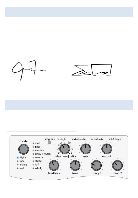
QUICKSTART
All modes are designed to sound good with all knobs at 12 o'clock.
Start there and then tweak to taste. Here’s a few others to try too.
Clean Digital Delay – Dotted Eighths
Page 3
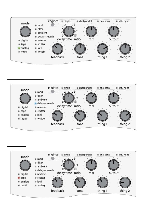
Warm Analog Delay
Delay and Reverb
Echoplex
Page 4
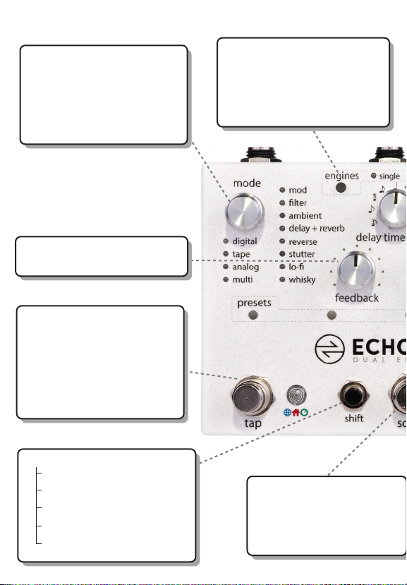
Controls at a Glance
mode selector: selects which
mode is active. Each mode can
have many submodes which are
indicated by dierent color LEDs.
when using dual engines, press
to switch active engine.
feedback: controls how long the
delay takes to decay.
tap: tap to enter a delay time.
also used to engage a preset
that has been scrolled to with
the scroll stompswitch.
hold tap to temporarily set
innite repeats (in most modes).
release to return to knob setting.
shift +
engine - switch engine order
mode btn- solo active engine
knob(s) - assign exp pedal
tap - select delay time source
scroll - save preset
engines: press to cycle through
the 4 dierent routing modes.
hold tap and press engines to
send current tempo from the
active delay to the other delay
scroll: press to scroll through
presets, then engage the preset
with the tap switch.
scroll + tap: will scroll
backwards through presets.
Page 5
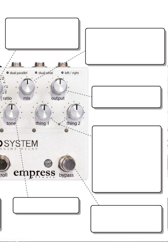
delay time | ratio: controls
the delay time. in tap mode, it
controls the ratio of the delay
time relative to the tempo
that is tapped.
mix: sets the ratio of wet signal
(delay) to dry signal (unaected).
Counterclockwise is 100% dry,
clockwise is 100% wet, with 50/50
being somewhere around 2 o’clock.
output: controls the overall
output volume for the pedal.
12 o’clock is unity.
thing 1 & thing 2: these two
controls take on dierent
functions depending on the
mode. They control things like
modulation depth and speed,
saturation, panning, lter, and
reverb controls
Check the mode reference chart
to see which function they
perform in a given mode.
tone: use to apply EQ to the
delay line. center is neutral.
bypass: engage or bypass the
pedal. Can be set for true bypass
or buered bypass in advanced
conguration.
Page 6
MODE REFERENCE CHART
Mode
Description
Thing 1
Thing 2
Digital
Pristine
Clean and pristine
Modulation
Depth
Modulation
Rate
Short Stuff 1980
Divides tap time by 4 for
really short sounds.
Perfect for slap-back
Mod Depth
Bandwidth
Ping Pong
Classic ping pong delay
Modulation
Depth
Modulation
Rate
Dynamic Duck
Wet signal gets turned
down when guitarist plays
louder, turns back up for
trails
Duck Amount
Release Speed
Dynamic
Feedback
Feedback signal gets
compressed by the input
signal
Duck Amount
Duck Threshold
Tape
New Tape
Good bandwidth with
some wow and flutter
Modulation
Depth
Modulation
Rate
Old Tape
The warm awesomeness
of old tape
Modulation
Depth
Modulation
Rate
Echoplex
Echoplex emulation
Saturation
Modulation
Width
Space Echo
RE-201 single tap
emulation
Input Drive
Modulation
Width
Analog
BBD
Bucket brigade delay
Saturation
Modulation
Tube BBD
Like above but tubey to
the max
Saturation
Modulation
Deluxe Memory
Boy
Classic emulation. Usually
you choose between v.
and c. but we let you stack
them
Vibrato Amount
Chorus Amount
Page 7
Multi
Digital Multi
Multitaps
Intensities
(one per dot)
Intensity Depth
and pan width.
Tone Taps
The tone of each tap is
different
Tone Variations
(one per dot)
Intensity Depth
and Pan Width.
Preset Pattern
Mode
It takes a single tap and
uses a selectable pattern
of multi-taps
Delay Time
Pattern
(one per dot)
Volume and Pan
Variation
(one per dot)
Mod
Panning Delay
Delay line pans back and
forth
Pan Width
Pan Speed
Trem Delay
Tremolo on the output
Trem Depth
Trem Speed
Waveform
Modulation shapes
Waveform
(one per dot)
Modulation
Filter
Filter Pulse
Moving filter on delay
signal
Pulse Center
Frequency
Pulse Speed
Filter Warp
Filter on wet output
moves around depending
on volume of the delay
Filter Sensitivity
Response Speed
Swoosh Echo
Filtered delays that
swoosh down in tone
Modulation
Swoosh Speed
Ambient
Drunk Ewok
(lost in space)
Somewhere between
multitap delay and reverb
Delay Pattern
(one per dot)
Diffusion
Triggered Swell
Input to delay line is
ducked when it detects
the onset of a note
Swell Time
Modulation
Triggered Multi
Swell
Like previous mode, but
multi-tap
Swell Time
Flanger Amount
(which provides
stereo width)
Long Delay
Knob time goes up to 8
seconds
Modulation
Depth
Modulation
Rate
Page 8
Delay + Reverb
Hall
Delay and hall reverb
Mix of Delay to
Reverb
Reverb Decay
Plate
Delay and plate reverb
Mix of Delay to
Reverb
Reverb Decay
Reverse
Reverse Delay
Chops the input signal up
and plays it backwards
High Frequency
Roll-Off
Compression
Amount
Reverse Dual
Pitch
Has two pitch shifted
reverse delays
(unity, +-10cents, +-4th, +5th, +-octave)
Sets pitch of
delay 1
Sets pitch of
delay 2
Triggered
Reverse
When a trigger is detected
it resets the reverse
counter, and triggers a
swell
Swell Time
Chorus Level
Stutter
Chop Mode
Signal gets chopped up
before feeding the delay
Chop Speed
Modulation
Auto Stutter
Detects a note then
stutters on that note.
Stutter repeats cycle
through filter sets.
Feedback knob adds
distortion.
Filter sequence
(one per dot)
Filter
Aggressiveness
Lo-Fi
Old Timer
Lo-fi with resonant filters
Oldness
Break-up
amount
Digital Death
Robot alias
Aliasing Freq
Alias Blend
Page 9
Whisky
Knobs' Seesaw
Two pitched delay lines.
When input signal gets
above a threshold it
switches from one line to
the other.
Sets pitch
when playing
quiet
Sets pitch when
playing gets
louder
Christopher
Glitchens
Two pitched delays that
have fully variable pitch
control -1 octave to +1
octave.
Sets pitch of
delay 1
Sets pitch of
delay 2
This manual only lists modes that were available at the time of printing.
For the most up-to-date firmware and manual refer to empresseffects.com
Page 10

SETTING DELAY TIME
To change the delay time source, hold the shift button and
press the tap stompswitch.
DELAY TIME SOURCES
Local Tap (Tap LED shines Red): When the user taps in a tap
time, it gets scaled by the ratio knob, and is saved with the
preset.
Global Tap (Tap LED shines Blue): When the user taps in Global
Tap, it sets the global tap time. This Global Tap propagates to
any other modes running with Global Tap. If you load a new
preset that has Global Tap, it will use this time. Each preset and
engine applies its own ratio setting to the global tap time
making it easy to sync delays at musical ratios.
Knob (Tap LED shines Green): Turning the knob adjusts the
delay time from 20ms to 1.2s (in most modes).
MULTI-TAP
Multi-tap modes allow you to tap in a sequence of up to 5 taps.
The tap LED will blink the sequence tapped, with the ratio
applied, and then pause for 2 seconds. Multi-tap modes have
their own global tap.
Page 11

USING DUAL DELAY ENG INES
The Echosystem has two engines which can each run any
mode. You can route these engines in parallel, serial, or split
left/right.
When using dual engines, two mode LEDs light up. The bright
one is the mode whose controls are active. Press down on the
mode knob to toggle which mode is active.
SYNC DELAY TIMES BET WEEN ENGINES
Hold the tap stomp and press the engines button, and the
delay time from the bright mode will be sent to the dimmed
mode. Note: The delay time sent to the other mode is the time
you tapped (pre-ratio) and the dimmed mode will apply its
ratio to that tapped time. This makes it easy to have the modes
in sync at different ratios. Both modes must be set to tap
tempo to sync delay times.
SOLO AN ENGINE
When getting sounds while using dual engines, it can help to
mute the dimmed mode temporarily. Hold the shift button and
press down on the mode knob to solo the active mode. The
active mode LED will blink while solo’d. To return to normal
operation press the mode knob again.
Page 12

PRESETS
The Echosystem has two types of preset systems: the scrolling
preset system, and the bank preset system. Read about each
preset system to find which one will work best for you. Select
which preset system to use in Advanced Configuration.
SCROLLING PRESET SYSTEM
Preset Organization
In Advanced Configuration you can select the number of
presets you wish to use. The presets are represented by a
series of five LEDs located just below the knobs. Press the scroll
stompswitch to scroll through the presets. The preset LEDs will
blink. When cycling through the presets, after every five
presets, the preset LED colors will change to another color to
indicate you're in the next bank and will start counting again
from left to right.
When cycling through the presets, after your final preset, all
the preset LEDs will flash very quickly. This represents the
manual preset. If you recall this preset, the Echosystem will get
its settings from the current knob positions. In the manual
preset, no preset LEDs are lit.
You can scroll backwards through the presets by pressing the
tap and scroll stompswitches simultaneously.
Page 13

Saving a Preset
To save the current settings to a preset, press the scroll
stompswitch until you reach the preset location where you
want to write. While the lights are flashing, hold down the shift
button and press the scroll stompswitch. Your preset is now
saved.
Recalling a Preset
To recall a preset simply press the scroll stompswitch until the
preset you’d like to recall is flashing, then press the tap
stompswitch to load the preset. The presets LEDs should now
be solid and bright.
What settings are saved in my preset?
If you change the position of a knob or switch after a preset is
loaded, the preset LEDs will dim to indicate that the preset has
been modified, but not saved. If you move the knob or switch
back to the position it was in when the preset was saved, the
preset’s LED indicators will brighten again. This lets you find the
positions of all the knobs and switches when the preset was
saved.
Page 14

BANK PRESET SYSTEM
Preset Organization
In Advanced Configuration you'll select the number of banks
you wish to use. The preset LEDs display which bank is selected
by changing color. The middle and right stompswitches each
represent a preset. So there are two presets per bank.
Recalling a Preset and Bypassing the Pedal
To recall a preset, press on the middle or right stompswitch.
The light above that stompswitch and the bypass LED will
illuminate. To load another preset, simply press the other
stompswitch. To bypass the pedal, press the stompswitch
corresponding to the active preset, and the bypass LED will
turn off. The pedal is now bypassed.
Changing Banks
To bank up, press the right and middle stompswitches
simultaneously. To bank down, press the left and middle
stompswitches simultaneously. The LEDs will flash indicating
the target bank, then you can press any of the stompswitches
to load a preset within that bank.
Saving a Preset
To save a preset, set the knobs to the sound you would like to
save, then navigate to the target bank. While the lights are
blinking, press and hold the shift button and select the target
preset location by pressing the corresponding stompswitch.
Page 15

BANK PRESET SYSTEM - WITH EXTERNAL TAP
If you'd like three presets per bank, you can use an external tap
switch. By setting the pedal's Advanced Configuration to bank
presets and the control port setting to either normally-open tap
or normally-closed tap you will get 3 presets available per bank.
(Changing the delay time source is done by holding the shift
button and pressing the external tap in this configuration.)
Page 16

CONTROL PORT
The control port jack allows the Echosystem to be controlled by
a multitude of devices. The pedal ships configured to accept an
expression pedal. Please see the Advanced Configuration
section on how to configure the control port for the device you
plan to use.
EXPRESSION PEDAL
Each parameter, with the exception of the mode knob, can be
controlled simultaneously via the expression pedal.
To control a parameter with the expression pedal, move the
parameter's knob to the desired heel setting, then hold down
the shift button and move the knob to the desired toe setting,
then release the shift button. Multiple parameters can be
assigned for expression pedal control simultaneously by
repeating this process for each parameter to be assigned. Each
parameter can be set with independent heel and toe settings.
To release a parameter from the expression pedal's control,
move the knob that controls that parameter.
Any expression pedal used with the Echosystem should have
the following pinout: tip to signal, ring to power, and sleeve to
ground.
Page 17

CONTROL VOLTAGE (CV)
With CV control, the Echosystem responds to CV signals from 0
to 5 volts. Otherwise, the CV configuration works exactly like
the expression pedal configuration.
EXTERNAL TAP SWITCH
The Echosystem can be used with either a normally-open or a
normally-closed external switch. This switch operates like the
tap stompswitch, with the exception of loading presets.
MIDI
All the parameters of the Echosystem can be controlled via
control change messages. Its presets can be selected with
program change messages, and its tempo can be controlled
with MIDI clock messages.
To use MIDI with your Echosystem, you'll have to:
1. Connect the Empress Midibox (not included with the
Echosystem) using a ¼” patch cable to the control port. A
TRS cable is required to send MIDI out messages if you're
using the Echosystem to control other pedals.
2. Configure the pedal for MIDI control and set the MIDI
channel. See Advanced Configuration for instructions.
Choose a MIDI channel that won't conflict with other
devices in your MIDI rig.
Page 18

Recalling a preset via MIDI (Program Change Messages)
You can activate a preset by sending a MIDI program change
message. For example, sending a program change message of
7 activates preset 7.
Midi with Preset Out
The Echosystem can send out MIDI program changes on the
ring of the control port jack whenever a preset is loaded on the
Echosystem. The Echosystem will send out these program
changes on the 4 channels above the Echosystem's current
MIDI channel.
For example, if the Echosystem is set to MIDI channel 5
and preset 3 is loaded, the Echosystem will send out
MIDI program change 3 on MIDI channels 6, 7, 8 & 9.
Midi Beat Clock
Modes that accept a tap tempo input will respond to MIDI
clock messages. MIDI clock specifies quarter notes, subdivided
into 24 MIDI messages. The Echosystem's delay time gets set to
a quarter note.
Midi Control Changes
The Echosystem can be controlled with MIDI control change
messages. Opposite is a table that shows which MIDI control
change number controls each Echosystem parameter.
Page 19

MIDI CONTROL CHANGE MESSAGES REFERENCE
Echosystem
Parameter
CC#
Note:
Engine
A
Engine
B
Modes
100
109
The modes and sub-modes are
numbered starting from 0
(Digital = 0, Tape = 1, etc.) To
translate the modes and submode to a single number you
apply the following equation:
MIDI message value = (mode x
8) + sub-mode
Example: To load the 2nd tape
mode, you'd send a value of 9
with the CC message. (1x8) + 1.
Delay Source
101
110
0 - Knob, 1 - Local, 2- Global
Delay Time / Ratio
102 111
Sending a value 0 would be
equivalent to the knob
completely counterclockwise,
sending 127 is equivalent to
fully clockwise.
Mix
103 112
Volume
104
113
Feedback
105
114
Tone
106
115
Thing 1
107
116
Thing 2
108
117
Engage / Bypass
60
0 to bypass, 127 to engage
Recall Preset
11
Send preset # to load that
preset.
Simulate
Expression Pedal
10
0 to 127 as the sweep of the
expression pedal from heel to
toe.
Routing Mode
118
0 - Trails, 1 - Parallel, 2- Serial,
3 - Left/Right
Left Stomp - Tap
35
Page 20

Middle Stomp –
Scroll
36
Sending a value of 64
simulates a quick tap. Sending
a value of 127 simulates the
switch being pressed and held
until a value of zero is sent,
simulating releasing the
switch.
Right Stomp –
Bypass
37
Shift Button
38
MIDI Clock
Listener
51
52
Sending a value of 0 causes the
engine to ignore MIDI clock
messages. Sending a value of
127 causes the engine to listen
for MIDI clock messages. (by
default, the pedal listens for
MIDI clock messages)
Additional MIDI Control Change Notes
- MIDI switching cannot be done while in Advanced
Configuration.
- the manual preset cannot be used while using the bank preset
system.
Page 21

USING HARDWARE INSERT
External effects can be inserted into the delay line using
hardware insert. You’ll need to enable this mode in advanced
configuration. Then, connect as below:
In this configuration the unit operates in mono. Left/right
routing won't function as expected.
If using dual delays, the hardware insert goes on engine 0 (the
first delay when in series).
Page 22

ADVANCED CONFIGURATI ON
The advanced configuration customizes how your pedal
operates. The options are listed in the table that follows.
Entering Advanced Configuration
While holding down the tap and bypass stompswitches, press
the shift button. All the preset LEDs will blink yellow twice to
confirm you're in.
While in Advanced Configuration
Each mode LED represents a different configuration item you
can change. Look up the item you'd like to change from the
table on the right, then turn the mode knob to select it.
Turn the delay time knob to modify the value of the advanced
configuration setting. The preset LEDs will illuminate to show
you the current value. For example, if the blue digital mode LED
is lit and the 2nd preset LED is lit, you've configured the pedal
for buffered bypass operation.
Exiting Advanced Configuration
Hold down tap and bypass stompswitches while in advanced
configuration. Preset LEDs will blink yellow twice and the pedal
will reboot.
Page 23

ADVANCED CONFIGURATION REFERENCE
Option
Set mode LED to:
preset LEDs indicate:
Bypass operation
Digital
1. True hardwire bypass***
2. Buffered bypass.*
3. Buffered bypass with isolation
transformer on right output.
(Note: when transformer is engaged the
pedal assumes stereo output operation)
Control port
configuration
Tape
1. Expression pedal*
2. Control voltage input.
3. Normally-open switch.
4. Normally-closed switch.
5. MIDI.
6. MIDI with preset out.
Input pad
Analog
1. No pad (0dB)
2. -6dB pad*
3. -12dB pad
Preset system
Multi
1. Scrolling preset system*
2. Bank preset system
Number of presets for
scrolling preset system
Mod
As you turn clockwise, the LEDs
will illuminate in order to
indicate the last preset.
Number of banks for the
bank preset system
Filter
As you turn clockwise, the colors
will indicate the last bank.
MIDI channel the pedal
will respond to (when
control port is configured
for MIDI).
Ambient
As you turn from left to right the
LEDs will illuminate in order to
indicate the MIDI channel. (ex. If
the 3rd LED is lit, it's going to
listen on MIDI channel 3).
Knob Lock - lock the
presets so they don't
change accidentally on
stage.
Delay + Reverb
1. Unlocked.*
2. Locked - knobs are locked in
presets (not manual preset) so
that they don't get nudged by
mistake if using presets.
Page 24

Cabinet Simulator
puts a cabinet simulation
algorithm on the output,
useful if you don't have
an amp.
Reverse
1. Cab sim is off.*
2. Bright 4x12 cab.
3. Dark vintage cab
4. Balanced modern cab
Signal Configuration
Stutter
1. stereo in/stereo out.*
2. wet/dry: dry out left, and wet
out right. (mix controls wet
volume, output controls dry) **
3. hardware insert mode.**
Startup State
Lo-Fi
1. Startup bypassed*
2. Startup engaged and load
preset 1
Stereo Widening
Whisky
1. Regular stereo width*
2. Stereo width 2dB wider.
3. Stereo width 4dB wider.
*denotes the factory default setting
** left-right routing doesn't work with these configs.
*** In signal configuration wet/dry and hardware insert true bypass isn't available.
Page 25

FIRMWARE UPDATES
This pedal has firmware that can be updated with an SD card.
Performing A Firmware Update
1) download the firmware file off the website
www.empresseffects.com/echosystem-firmware
2) copy the file to the root directory of the SD card
(a high-capacity SD card that's been formatted FAT32)
3) insert the SD card then power on the pedal.
4) The preset LEDs should marquee yellow for a bit, then all
turn green when the update is complete.
5) remove SD card, cycle the pedal's power, and you're good!
SD Card Constraints
There should only be one partition on the SD card because the
pedal only looks at the first partition on the disk. SD card must
be V2 high speed. Nowadays this is the most common type.
Firmware Update Error Codes
The preset LEDs will blink to signal an error:
1. unusable card
2. V1 card
3. V2 standard card
4. unable to read disk
5. valid FAT volume not found on SD card.
Page 26

FACTORY RESET
WARNING! This will overwrite your current presets and advanced
config settings and replace them with the factory presets and
default advanced config settings!
To restore the Echosystem to its factory settings, do the
following: while in the advanced configuration (see Entering
Advanced Configuration): press and release the stompswitches
in this order: Tap, Bypass, Tap, Bypass. Then the LEDs do a
dance. Now you can exit advanced configuration (see Exiting
Advanced Configuration).
POWERING THE ECHOSYS TEM
Go to www.empresseffects.com/power for a full list of
compatible power supplies.
Please Note: The Echosystem requires at least 300mA of
current to function properly. Any power supply rated at 9V DC,
supplying negative tip polarity ( ) and at least 300mA
of current should work.
Page 27

THANK YOU
Paul Uhl, Gabriel Tanaka, Patrick Zdunich, Knobs, Matt Cyr,
Steve Foley.
LEGAL STUFF
FCC Compliance
Note: This equipment has been tested and found to comply with the limits for a
Class B digital device, pursuant to part 15 of the FCC Rules. These limits are
designed to provide reasonable protection against harmful interference in a
residential installation. This equipment generates, uses and can radiate radio
frequency energy and, if not installed and used in accordance with the
instructions, may cause harmful interference to radio communications.
However, there is no guarantee that interference will not occur in a particular
installation. If this equipment does cause harmful interference to radio or
television reception, which can be determined by turning the equipment off and
on, the user is encouraged to try to correct the interference by one or more of
the following measures:
- Reorient or relocate the receiving antenna.
- Increase the separation between the equipment and receiver.
- Connect the equipment into an outlet on a circuit different from that to which
the receiver is connected.
- Consult the dealer or an experienced radio/TV technician for help.
Modifications not expressly approved by the manufacturer could void the user's
authority to operate the equipment under FCC rules
Page 28

SPECIFICATIONS
Input Impedance:
1MΩ
Output Impedance:
100Ω
Output Impedance (transformer):
600Ω
Frequency Response (-3dB, dry):
10Hz – 50kHz
Frequency Response (-3dB, wet):
10Hz – 23.4kHz
Total Harmonic Distortion (dry):
0.09%
Total Harmonic Distortion (wet):
0.22%
Dynamic Range (dry):
106.9 dBA
Dynamic Range (wet):
105.5 dBA
Input Headroom (dry):
+10.0 dBu
Input Headroom (wet, no pad):
+0.5 dBu
Input Headroom (wet, 6dB pad):
+5.7 dBu
Input Headroom (wet, 12dB pad):
+10.8 dBu
Output Headroom:
+16.2dBu
Power Input Connector:
Power Input Voltage:
Required Current:
Height (enclosure only):
Height (including controls):
Length:
Width:
Weight:
2.1mm Barrel Connector
9V
300mA
1.75”
2.25”
5.7”
3.75”
1.5lbs
www.empresseffects.com
 Loading...