

Page 1

User Manual
WAP655-C
Version 1.0
0
Page 2

IMPORTANT
ToinstallthisAccessPoint
Please refer to the
QuickInstallationGuideincluded in the product packaging
1
Page 3
Chapter1
ProductOverview
2
Page 4

Introduction
Key Features
・Built-in Turbo Engine with Quad-Core powerful chipset to process multiple tasks for driving
and enhancing performance effectively.
・Support 802.11ac Wave 2.0 technology to enhance bandwidth and connecting speed.
・Dual radio 2x2 802.11 ac/a/b/g/n AP, support up to 867 Mbps in 5GHz frequency band and 400 Mbps in 2.4GHz frequency band (with 2ss/VHT40
clients)
・RF circuity is designed and tuned for improved transmit and receive wireless coverage.
・Compliance with 802.3at or Proprietary 48-54V PoE Input for flexible installation.
・Operation mode options for different requirements.
The 802.11ac high performance Access Point with MU-MIMO technology for high-density use on multiple applications
Emplus Wireless Access Point solution is designed for versatile outdoor applications. To meet various requirements for different networking
environment, Emplus provides the most flexible and effective solutions as your expectations.
The state-of-the-art 802.11ac and MU-MIMO technology brings high performance on connecting speed and bandwidth. WAP655-C equips with two
powerful RF interfaces which support up to 867 Mbps in 5GHz frequency band and 400 Mbps in 2.4GHz frequency band (with 2ss/VHT40 clients).
Features
3
Page 5
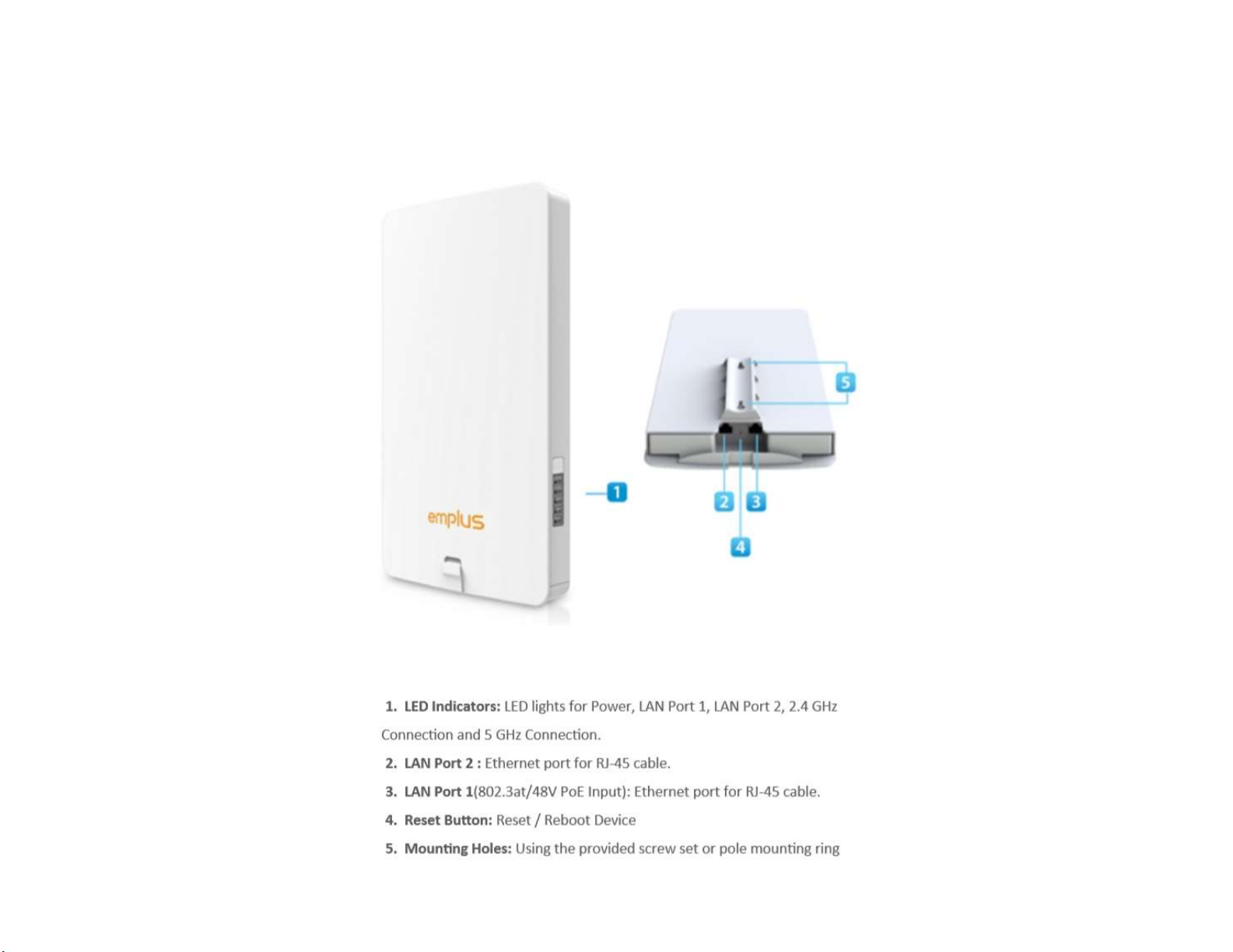
Physical Interface (WAP655-C)
4
Page 6

Physical & Environment
Power Source
Internal High Gain Antenna
(Peak Gain)
PoE: compatible with 802.3af/at
~3.55dBi 2.4GHz antennas
~5.7dBi 5GHz antennas
1 x 10/100/1000Mbps Ethernet Port with 802.3af/at PoE
Interface
1x 10/100/1000Mbps Ethernet Port
1 x reset button
Dimensions (W x D x H) 300x181x34.1 mm
Mounting Pole and Wall mount
Operating temperature: -20°C~65°C
Environment
Operating humidity: 0%~90% typical
Technical Specifications Storage temperature: -30°C~80°C
5
Page 7

Applications
Wireless LAN (WLAN) products are easy to install and highly efficient. The following list describes some of the many applications made possible through the power and
flexibility ofWLANs:
Difficult-to-Wire Environments: There are many situations where wires cannot be installed, deployed easily, or cannot be hidden from view. Older buildings, sites
with multiple buildings, and/or areas that make the installation of a Ethernet-based LAN impossible, impractical or expensive are sites where WLAN can be a
network solution.
Temporary Workgroups: Create temporary workgroups/networks in more open areas within a building; auditoriums, amphitheaters classrooms, ballrooms,
arenas, exhibition centers, or temporary offices where one wants either a permanent or temporary Wireless LAN established.
The Ability to Access Real-Time Information: Doctors/Nurses, Point-of-Sale Employees, and/or Warehouse Workers can access real-time information while
dealing with patients, serving customers, and/or processing information.
Frequently Changing Environments: Set up networks in environments that change frequently (i.e.: Show Rooms, Exhibits, etc.).
Small Office and Home Office (SOHO) Networks: SOHO users require a cost-effective, easy, and quick installation of a small network.
Training/Educational Facilities: Training sites at corporations or students at universities use wireless connectivity to exchange information between peers and
easily access information for learning purposes.
6
Page 8

Chapter2
Before YouBegin
7
Page 9
Computer Settings
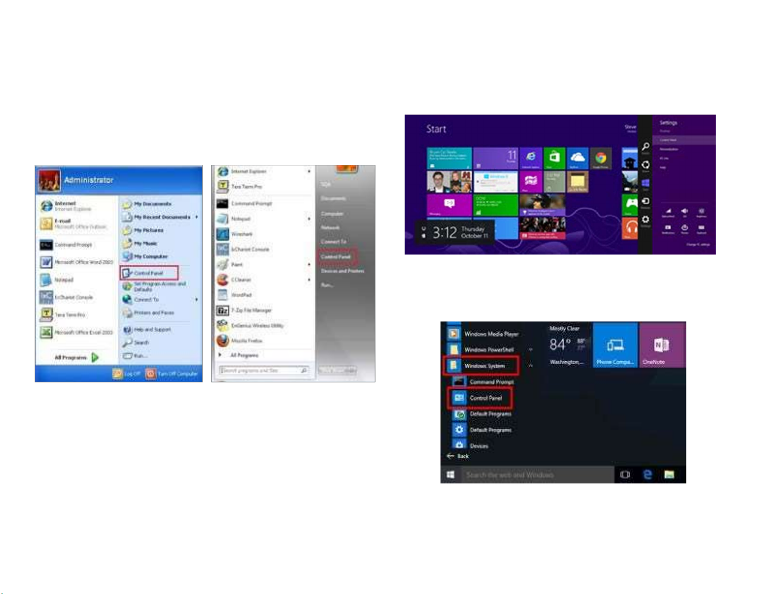
Windows XP/Windows 7/Windows 8/Windows 10
In order to use the Access Point, you must first configure the
TCP/IPv4connectionofyourWindowsOScomputersystem.
1a. Click the Start button and open the Control Panel
1b. Move your mouse to the lower right hot corner to display the Charms
Bar and select the Control Panel in Windows 8OS.
Windows 8
1c. In Windows10, click Start to select All APP stoenter the folder of
Windows system for selecting Control Panel.
WindowsXP Windows7
Windows 10
8
Page 10
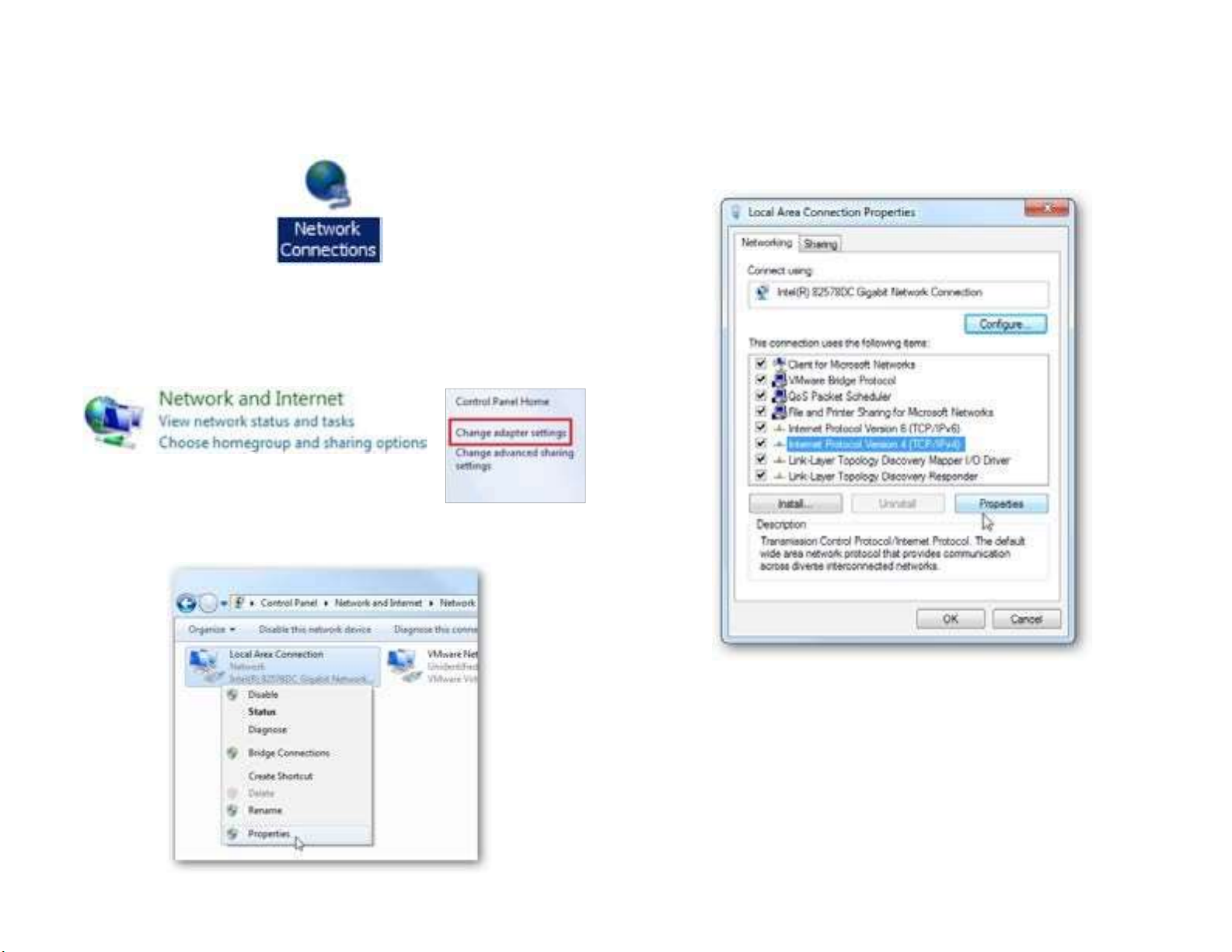
2a. In Windows XP, click Network Connections.
2b.In Windows7/Windows8/Windows10, click View Network
Status and Tasks in the Network and Internetsection, then
select Change adapter settings.
Right click on Local Area Connection and select Properties.
3.
Select Internet Protocol Version 4 (TCP/IPv4) and then select
4.
Properties.
5.
Select Use the following IP address and enter an IP
is different from the Access Point and Subnet
9
mask, then click OK.
address that
Page 11
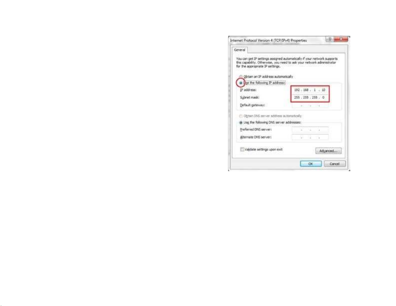
Note: EnsurethattheIPaddressandSubnetmaskare on the same
subnet as the device.
For example: WAP655-C IP address: 192.168.1.1
PC IP address: 192.168.1.2–192.168.1.255
PC Subnet mask: 255.255.255.0
10
Page 12
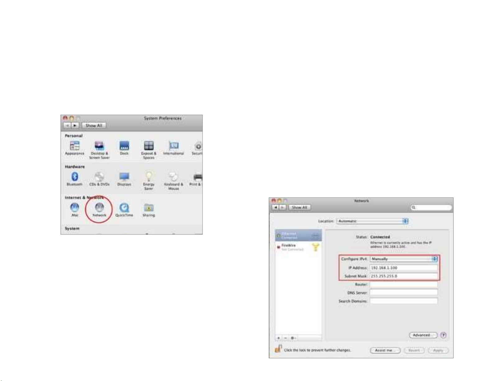
Apple Mac OSX
1.
Go to System Preferences (Which can be opened in the
4.
In Configure IPv4, select Manually.
5.
Enter an IP address that is different from the Access
Point and
Applications folder or selecting it in the Apple Menu).
Select Network in the Internet & Network section.
2.
HighlightEthernet.
3.
Subnet mask then press OK.
Note: Ensure that the IP address and Subnet mask are on the
same subnet as the device.
For example: A device IP address: 192.168.1.1 PCIPaddress:
192.168.1.2–192.168.1.255
PCSubnetmask:255.255.255.0
6.
Click Apply when done.
11
Page 13

Chapter 3 Configuring
Your Access Point
12
Page 14
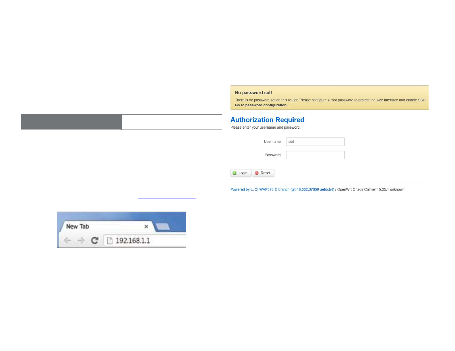
ConfiguringYourAccessPoint
IP Address
192.168.1.1
Username / Password
none
This section will show you how to configure the device using
the web-based configuration interface.
2.
The default username and password are admin. Once you have
entered the correct user name and password, click the Login
Default Settings
Please use your Ethernet port or wireless network adapter to
connect the Access Point.
Web Configuration
1.
Open a web browser (Internet Explorer/Firefox/Safari/
Chrome) and enter the IP Address http://192.168.1.1
button to open the web-base configuration page.
* The model name will be varied by different models.
3.
If successful, you will be logged in and see the User
Note: If you have changed the default LAN IP Address of
The Access Point, ensure you enter the correct IP Address.
Menu of this Access Point.
13
Page 15

Chapter4
Building aWireless
Network
14
Page 16
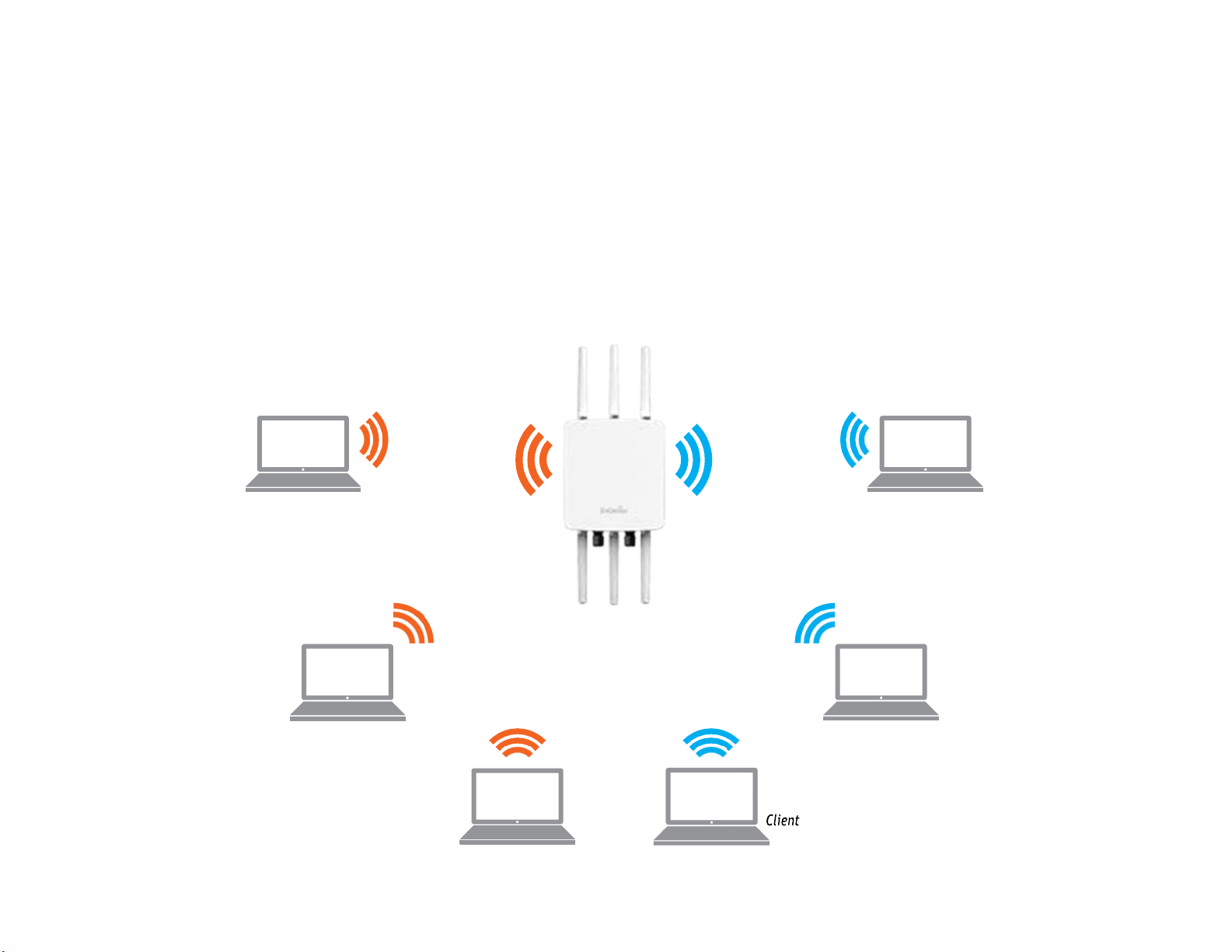
Before starting to configure this Access Point, you may realize the used scen a rounder varied operating modes. The AP has the ability
to operate in various modes. This chapter describes purpose of different operating modes and lists down the operating modes for
outdoor Access Points or Client Premise Equipments(CPE).
Access Point Mode
In Access Point Mode, AP be have slikes a central connection for stations or clients that support IEEE802.11ac/a/b/g/n networks. The
stations and clients must be configured to use the same SSID(Service Set Identifier) and security password to associate with the AP.
The AP supports up to eight SSIDs per band at the same time for secure access.
AP
Access Point
Client
2.4GHz
5GHz
Client
Client Client
Client
15
Page 17
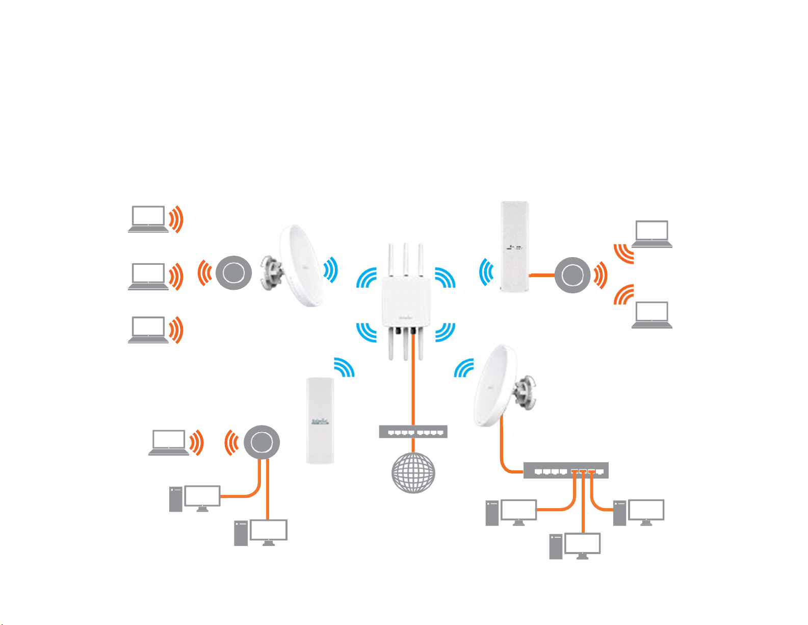
Client Bridge Mode
The Access Point essentially acts as a wireless adapter that connects to an access point to allow a system of wireless access to the
network in the Client Bridge mode. Since the computers are on the same subnet, the Access Point can broadcast or each all enddevices.
If you use the client bridge mode in this Access Point, you can use the AP Detection feature to scan for Access Points within range.
When you find an Access Point, configure this Access Point to use the same SSID and Security Password as the Access Point to
associate with it.
16
Page 18
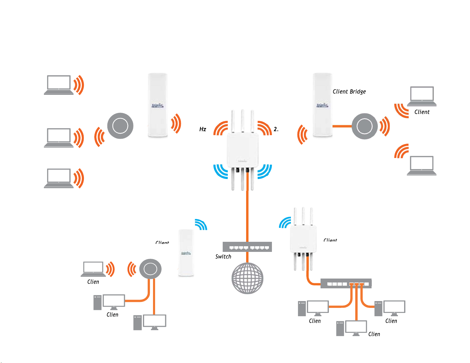
5GHz
5GHz
AP
ENH500
The AP can be used as a centralized Outdoor Access Point with which other Wireless 802.11b/g/n2.4 or ac/a/n 5GHz Outdoor Client
Bridge scan associate; leveraging the long-range capability of their internal high-gain directional antennas, resulting in a very costeffective solution to expand a company network over a multiple building campus.
Client
ENH202
Client Bridge
AP
Access Point
ENH202
2.4 G
4 GHz
Client
Client
Client
Client
Internet
Page 19
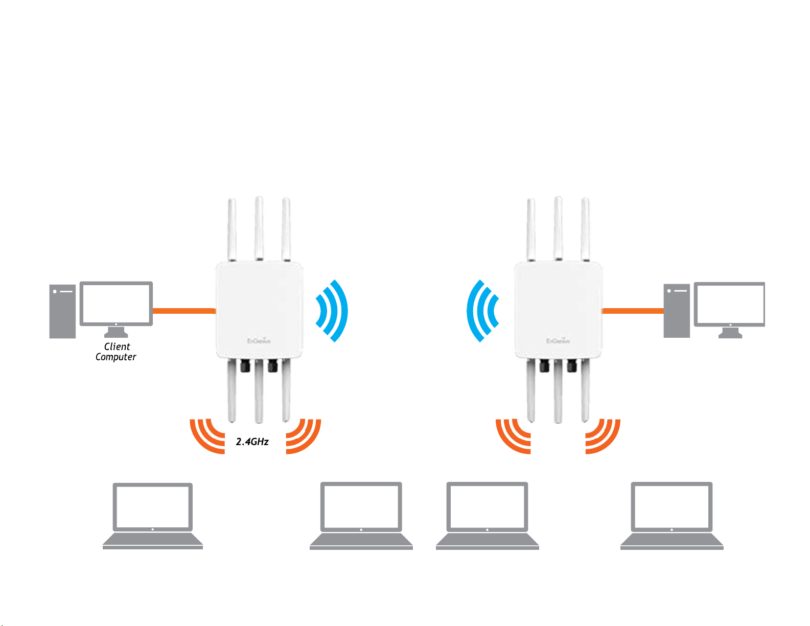
WDS APMode
5GHz
The AP also supports WDS AP mode. This operating mode allows wireless stations to connect with Access Point via using WDS
technology. In this mode, configure the MAC addresses or SSIDs in both Access Points to enlarge the wireless area by enabling WDS
Link settings. WDS AP mode supports up to four(4) AP MAC addresses and four(4) SSIDs at the same time.
AP
WDSAP
5 GHz
AP
WDS AP
Client
Computer
2.4 GHz
Client Client Client Client
Page 20
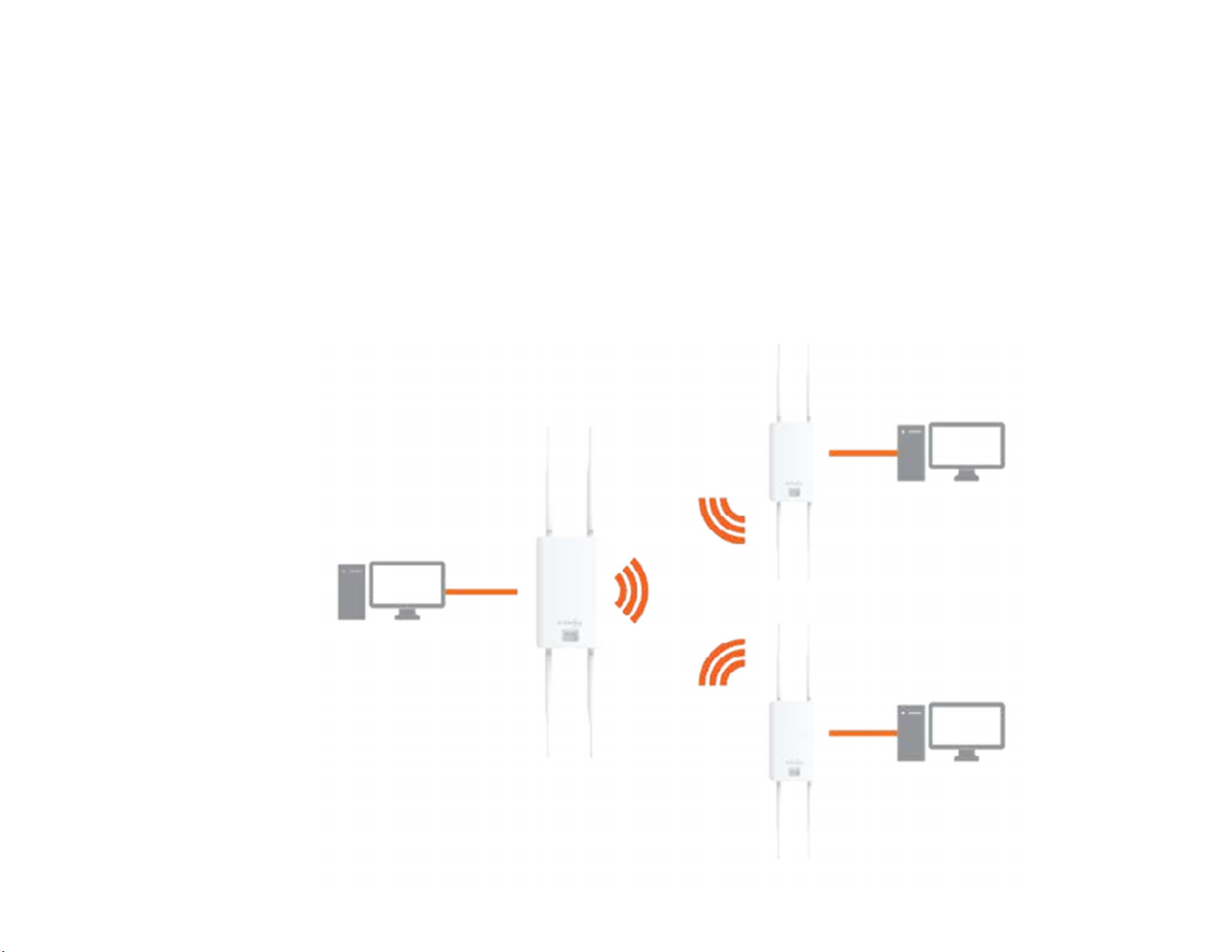
WDS Bridge Mode
In WDS Bridge Mode, the Access Point can wirelessly connect different LANs by configuring the MAC address and security settings of
each Access Points. Use this operating mode when two wired LANs located as mall distance apart want to communicate with each
other. The best solution is to use the Access Point to wirelessly connect two wired LANs, as shown in the following diagram.
WDS Bridge Mode can establish up to four (4) to eight (8) WDS links, creating a star-like network.
Note: WDS Bridge Mode does not act as an Access Point. Access Point slinked by WDS are using the same frequency channel. More
Access Points connected to get her may lower throughput. This configuration can be susceptible to generate endless network loops
in your network, so it is recommended to enable the Spanning Tree function to prevent this from happening.
AP
WDS Bridge
Client
Computer
AP
WDS Bridge
Client
Computer
Client
Computer
AP
WDS Bridge
Page 21
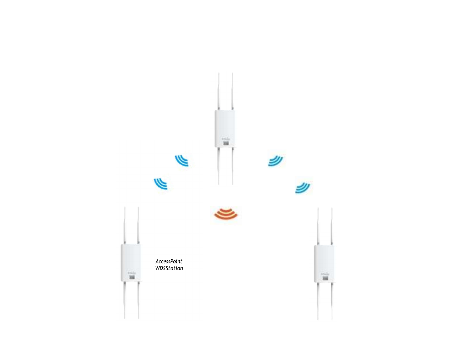
WDS Station Mode
WDS station(WDS STA) mode expands the WDS by receiving a wireless signal/service and sharing it through the Ethernet port. With
WDS STA mode,
Access
Point
WDS
AP
on both 5 GHz or 2.4 GHz
Access
Point
WDS
Station
20
Page 22

Chapter5
Status
21
Page 23
Overview
SaveChanges
This page lets you save and apply the settings shown under
Unsaved changes list, or Revert the unsaved changes and revert
to the previous settings that were in effect.
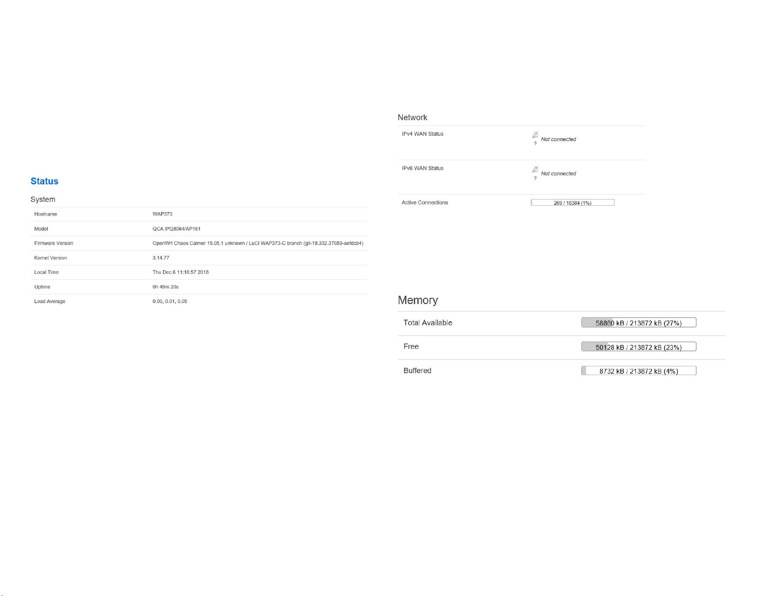
Device Status
Clicking the Device Status link under the Overview menu
shows
Note: VLAN ID is only applicable in Access Point, WDS
AP or WDS BR mode.
•
The Memory Information section shows usageof
Memory such as Total Available, Free, Cached, Buffered
the status information about the current operating
•
The Device Information section shows general system
information such as Device Name, MAC Address, Current
Firmware Version, and Management VLANID
mode.
Time,
22
Page 24
•
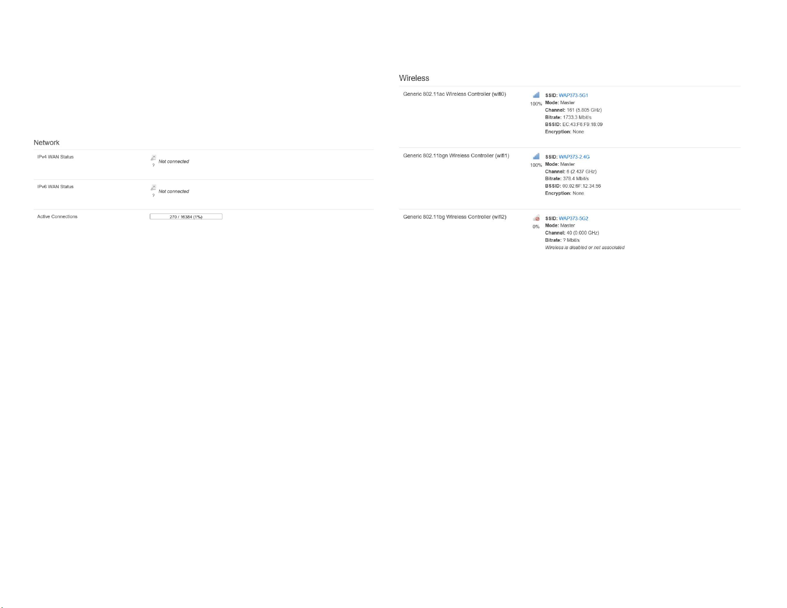
The LAN Information section shows the Local Area
Network
settings such as the LAN IP Address, Subnet
Address , Secondary DNS Address,
status of
Spanning Tree protocol (STP).
status of DHCP client, and
mask, Primary DNS
The Wireless LAN Information 2.4 GHz/5 GHz section
wireless information such as Operation Mode,
Channel. Since this Access Point supports multiple-SSIDs,
information about each SSID, the ESSID, and security settings, are
displayed
Note: Profile Settings are only applicable in Access Point and WDS
Frequency, and
shows
AP modes.
23
Page 25
Connections Realtime
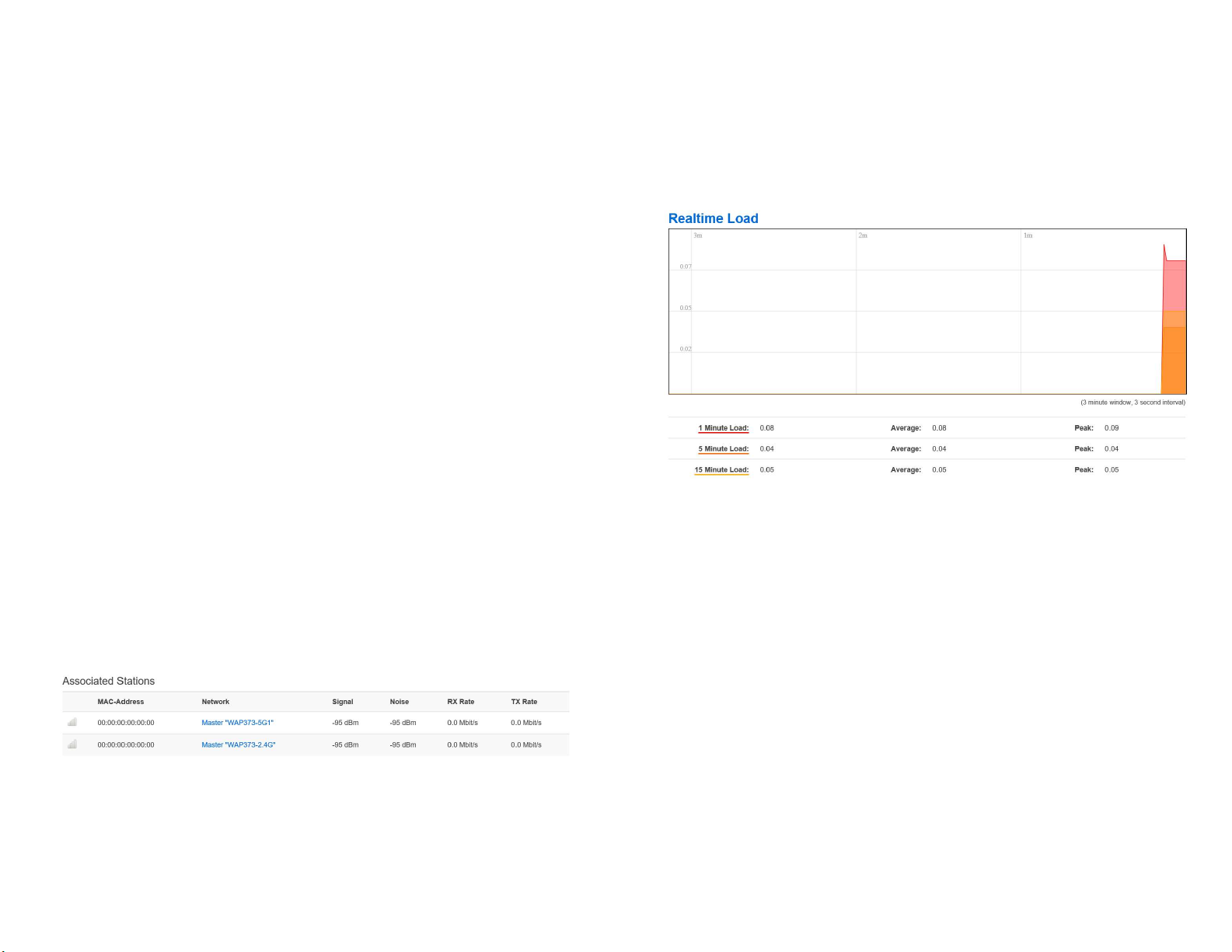
2.4 GHz/5 GHz Connection List
Click the connection link under the Overview menu displays
connection list of clients associated to the AP’s2.4
along with the MAC addresses and signal
strength for each
GHz/5 GHz,
client. Clicking Refresh updates the client list.
Note: Only applicable in Access Point and WDS AP modes.
2.4 GHz/5 GHz WDS Link List
Click the connection link under the Overview menu. This page
displays the current status of the WDS link, including
MAC Address, Link Status and RSSI.
Note:Only applicable in WDS AP and WDS Bridge modes.
WDS Link ID,
the
Realtime
The Realtime section contains the following options:
CPU Loading: 3 minutes CPU loading percentage
information, it
displays current loading, average loading and peak loading status.
Left bar is loading percentage;
button is time tracing. Interval is
every 3 seconds
24
Page 26

Chapter6
Network
25
Page 27
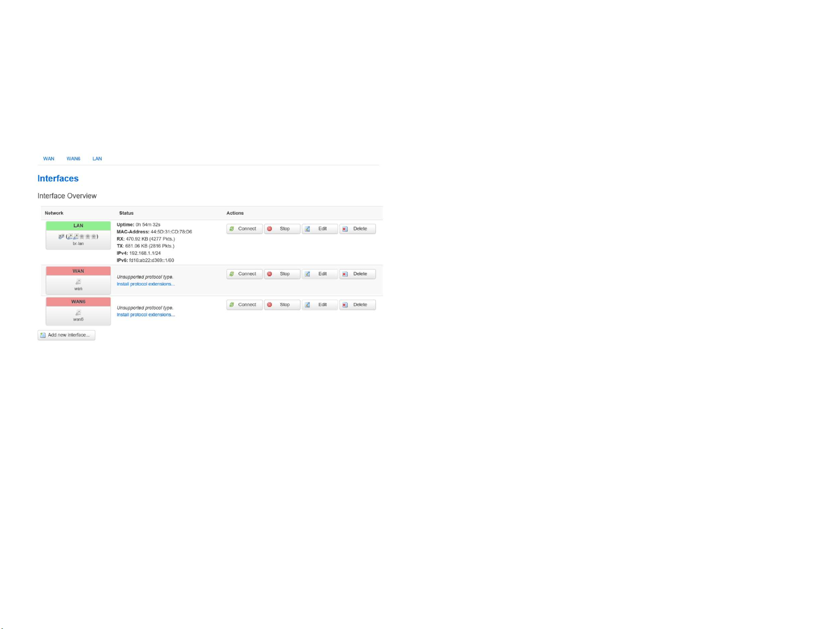
Basic
IPv4/IPv6 Settings
This page allows you to modify the device’s IP settings.
IP Network Settings: Select whether the device IP address will use a static IP address specified in the IP address field
automatically when the device connects to
a DHCP server. IP Address: The IP address of this device.
or be obtained
Subnet Mask: TheIP Subnet mask ofthis device.
Gateway: The Default Gateway of this device. Leave it blank if you are unsure of this setting.
Primary/Secondary DNS: The primary/secondary DNS address for this device.
Save: Click Save to confirm the changes.
26
Page 28

Chapter7
2.4GHz&5GHz
Wireless
27
Page 29

Wireless
Wireless Settings
Device Name: Enter a name for the device. The name you type
appears in SNMP management. This name is not the SSID and is
not broadcast to other devices.
Band Steering (Avaiable on WAP353): Enable Band Steering
to send 802.11n clients to the 5GHz band, where 802.11b/g
clients cannot go, and leave 802.11b/g clients in 2.4GHz to
operate at their slower rates.
feature, we suggest you to
SSID, as well as security settings must be the same. and
Steering supports following advanced settings,
Force 5GHz: When band steering is configured to Force
*
Before implementing this
assure the both 2.4GHz and 5GHz
Devices to network to the 2.4GHz band only if the client
devices are not currently associated on 2.4GHz radioin this
AP.
*Prefer 5GHz: When band steering is configured to Prefer
5GHz mode, the AP will steer dual band capable client
devices to 5GHz radio when the RSSI value of these client
devices on 5GHz radio is more than set one. The allowed RSSI
value for default setting is -75dBm.
*Band Balance: When band steering is configured to Band
Balance mode, the AP will steer dual band capable client
devices to 5GHz when the RSSI value of the seclient devices
on 5GHz radio is more than set one. To evenly allocate RF
resource on the both 2.4GHz and 5GHz radios, users also can
set the portion of client devices on 5GHz radio to assure
smoothly connection. The default value of the 5GHz radio is
75%.
Save: Click Save to confirm the changes.
5GHz mode, the AP will not dual band capable client
28
Page 30
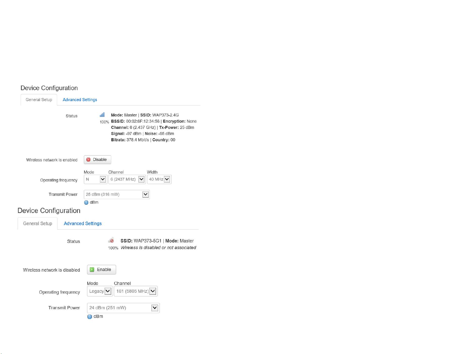
This page displays the current status of the Wireless settings of
this AP.
2.4 GHz/5 GHz Wireless Network
Operation Mode: Scrow down this list to select operation
implementing on this radio. The default operation
Point on base stations and Access Points
Client Premise Equipements(CPE).
Meanwhile, the outdoor devices
also support WDS modes for peer to peer or peer to multi-peer
connections.
Wireless Mode: Scrow down this list to select wireless
casting standard on 2.4GHz and 5GHz frequency
mode is Access
and is Client Bridge on
bands.
modes for
broad
29
Page 31

Channel HT Mode: Scrow down this list to select bandwidth for
operating under a frequency band. The default channel
bandwidth is 20MHz on 2.4GHz frequency radio and 40 MHz on
5GHz frequency radio. Considering the different
applications ,users can decide to implement a channel bandwidth
to fulfill real applications. The larger the channel, the greater the
transmission quality and speed.
Transmit Power (Tx Power): Default Tx power is Auto
to obey regulartory power of each country.
Channel: Click Configuration button to open a new windows to
configure channels for performing wireless service.
30
Page 32

*Default configuration: Default setting of channel selection is
“All” to perform auto channel on the exist channel list.
*None: Click “None” to disable the setting on this radio.
This radio is disabled.
*Group Configuration: Click specific groups of channels for
performing auto channel function. For example, users canclickU-NII1andU-NII-3toperformautochannelon
mechanism of this AP will select the
to perform wireless service.
these bands; the
relatively optimal channel
Data Rate: Select a data rate from the drop-down list. The data
rate affects throughput of data in the AP. Select the best balance
for you and your network but note that the lower the data rate,
the lower the throughput, though
transmission distance is also
Associated client devices will be restricted at this number.
Aggregation: Integrate multiple data packets into one packet
to deliver to client devices. This option reduces the number of
packets, but also increases packet sizes.
AP Detection: AP Detection can select the best channel to
use by
scanning nearby areas for Access Points.
Distance: Specifies the distance between Access Points and client
devices. The proper setting for this parameter
Points to avoid the improper operation
when transmitting data
may assist Access
under afield application.
Save: Click Save to confirm the changes or Cancel to cancel
and
return to previous settings.
lowered.
RTS/CTS Threshold: Specifies the threshold package size
RTC/CTS. A small number causes RTS/CTS packets to be
often and consumes more bandwidth.
Client Limits: Limits the total number of clients on this radio.
Once setting the ceiling of client numbers, the maximum
for
sent more
31
Page 33
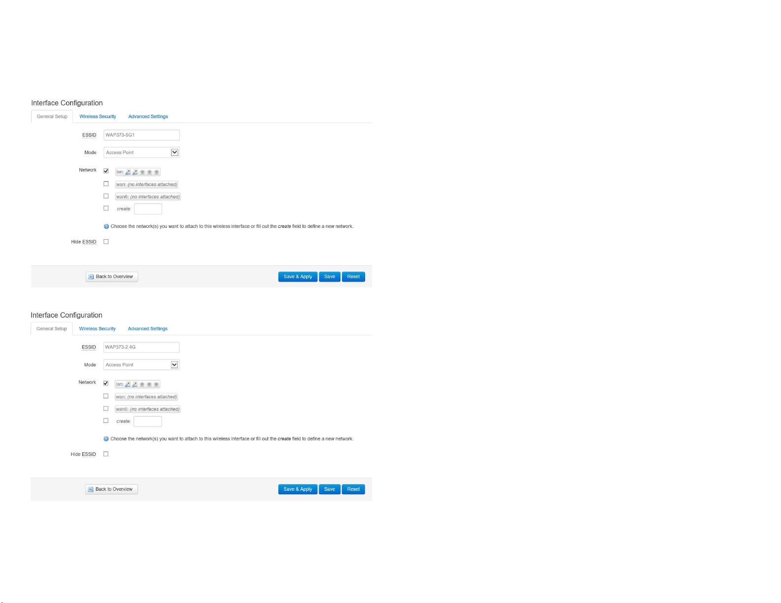
2.4 GHz/5 GHz SSID Profile
SSIDs (eight (8) per band). If multiple client
devices will be accessing
the network, you can arrange the devices into SSID groups. Click Edit to
configure the profile
and check whether you want to enable extra
SSID.
Current Profile: You can configure up to sixteen(16)
different
32
Page 34

Enable: Click this check box to enable this SSID interface.
The
default SSIDs are enable on the both first 2.4GHz and
5GHz SSID.
SSID: Specifies the SSID for the current profile.
Hidden SSID: Check this option to hide the SSID from clients.
Ifchecked, theSSIDwillnotappearinthesitesurvey.
Client Isolation: Click the appropriate radio button to enable
function for allowing or preventing communication
between
this
client devices.
VID: Specifies the VLAN tag for each profile. If your network includes
VLANs, you can specify a VLANID for packets pass
through the
Access Point with a tag.
Wireless Security: See the Wireless Security section.
VLAN Isolation: Restrict clients communicating with different
VIDs by selecting the radio button.
L2Isolation: Enable this function prevent client devices
communicate on the both WLAN and LAN.
Save: Click Save to accept the changes.
to
33
Page 35

Wireless Security
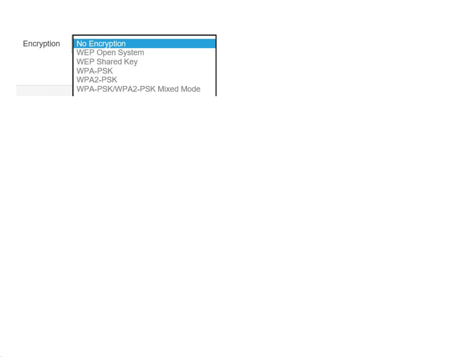
The Wireless Security section lets you configure the AP’s
security modes
Secuirty Mode: Including WEP, WPA-PSK, WPA2-PSK,
PSKMixed,WPA,WPA2,andWPAMixed.Westrongly
recommendyoutouseWPA2-PSKmode.
* Setting of WEP mode:
Auth Type: Select Open System or Shared Key.
WPA-
InputType
ASCII: Regular Text (recommended)
Numbers (For advanced users)
Key
Length: Select
clients use the same setting. Your choices are 64,
:
Hexadecimal
the
desired
option
and ensure
that
wireless
128, and 152-bit
password lengths.
Default Key: Select the Key you wish to be the default.
Transmitted data is ALWAYS encrypted using the Default
other Keys are for decryption only. You must enter
a Key Value for
Key; the
the Default Key.
Encryption Key Number: Enter the Key Value or values you wish
to use. Only the Key selected as Default is required.
The others
are optional.
34
Page 36
*
*SettingofWPA-PSK,WPA2-PSKandWPA-PSKMixed (PreSharedKey):
Encryption: You
encryption type you would like. Please ensure
may
select
AES,
TKIP
or
Both
(TKIP+AES)
to be the
that your wireless
clients use the same settings.
Pass phrase: Wireless clients must use the same Key to
associate the device. If using ASCII format, the Key must
63 characters in length. If using HEX format,
the Key must be
be from 8 to
64HEX characters in length.
Group Key Update Interval: Specifies how often, in
Group Key changes. The default value is 3600.
seconds, the
* Setting of WPA-Enterprise & WPA2-Enterprise (PreShared Key):
Encryption: Select the WPA encryption type you would like.
ensure that your wireless clients use the same settings.
Radius Server: Enter the IP address of the Radius server.
Radius Port: Enter the port number used for connections
Radius server.
Please
to the
35
Page 37

RadiusSecret:Enterthesecretrequiredtoconnecttothe
Radiusserver.
Radius Accounting: Enable or disable accounting feature.
Radius Accounting Server: Enter the IP address of the Radius
accountingserver.
RadiusAccountingPortEntertheportnumberusedfor
connectionstotheRadiusaccountingserver.
Radius
Accounting
Secret:Enter
the
secret
required
connect to the Radius accounting server.
Interim
Accounting
Interval:Specifies
how
often,
accounting data sends.
Note: 802.11n does not allow WEP/WPA-PSK TKIP/
TKIP security mode. The connectionmode
willautomaticallychangefrom802.11nto802.11g.
to
in
seconds, the
WPA2-PSK
36
Page 38

Wireless MAC Filtering
WirelessMACFilteringisusedtoallowordenynetwork
accesstowirelessclients(computers,tabletPCs,NAS,
smartphones,etc.)accordingtotheirMACaddresses.You
canmanuallyaddaMACaddresstorestrictpermissionto
accessthisAP.Thedefaultsettingis:DisableWireless MACFilter.
Note:
OnlyapplicableinAccessPointandWDSAP
modes.
ACLMode:Determineswhethernetworkaccessisgranted
ordeniedtoclientswhoseMACaddressesappearinthe
MACaddresstableonthispage.Yourchoicesare:Disabled,
DenyMACinthelist,orAllowMACinthelist.
MACAddress:EntertheMACaddressofthewirelessclient.
Add:ClickAddtoaddtheMACaddresstotheMACaddress
Delete: Delete the selected entries.
Save: Click Save to apply the changes.
table.
37
Page 39
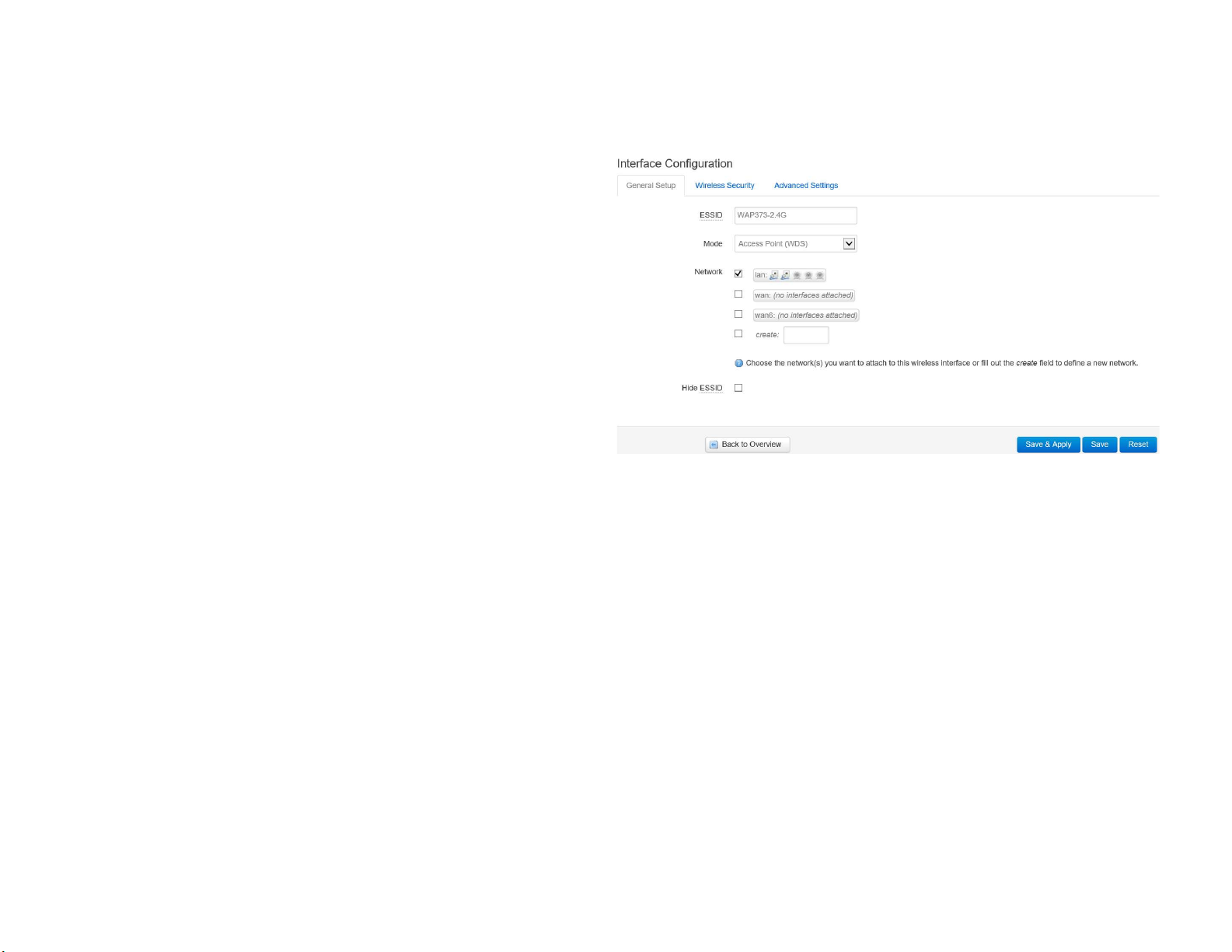
WDS Link Settings
UsingtheWDS(WirelessDistributionSystem)featurewill
allowanetworkadministratororinstallertoconnectto
AccessPointswirelessly.Doingsowillextendthewired
infrastructuretolocationswherecablingisnotpossibleor
inefficient
toimplement.
Note:Compatibilitybetweendifferentbrandsand models of
Access Points is not guaranteed. It is
recommendedthattheWDSnetworkbecreatedusing
thesamemodelsformaximumcompatibility.
Alsonote:AllAccessPointsintheWDSnetworkneed
tousethesameChannelandSecuritysettings.
TocreateaWDSnetwork,pleaseentertheMACaddresses
2.4 GHz/5 GHz WDS Link Settings
Security: SelectNone orAES fromthedrop-downlist.
AESPassphrase:EntertheKeyValuesyouwishtouse.
OtherAccessPointsmustusethesameKeytoestablisha
WDSlink.
oftheAccessPointsthatyouwantincludedintheWDS.
TherecanbeamaximumoffourAccessPoints.
Note:OnlyapplicableinWDSAPandWDSBridgemodes.
MACAddress:EntertheAccessPoint’sMACaddressto
where youwant toextend thewireless area.
Mode:Selecttodisableorenablefrom
the
drop-down
list.
Save: Click Save to confirm the changes.
38
Page 40
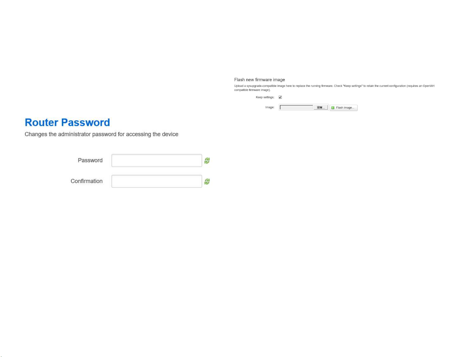
Account
This page allows you to change the AP usernameand
password.Bydefault,theusernameis:adminandthe
passwordis:admin.Thepasswordcancontainfrom0to
12alphanumericcharactersandiscasesensitive.
Account Settings
Firmware
Firmware Upgrade
Thispageallowsyoutoupgradethefirmwareofthe AP.
To Perform the FirmwareUpgrade:
1.
ClicktheChooseFilebuttonandnavigatetheOSfile
systemtothelocationoftheupgradefile.
2.
Selecttheupgradefile.Thenameofthefilewillappear
intheUpgradeFilefield.
Administrator
Username:Enteranew
username
for
loggingintotheNewNameentrybox.
CurrentPassword:Entertheoldpasswordforloggingin
to the Old Password entry box.
NewPassword:Enterthenewpasswordforlogginginto
the New Password entry box.
Verify Password: Re-enter the new password in the
ConfirmPasswordentryboxforconfirmation.
Apply: Click Apply to apply the changes.
39
ClicktheUploadbuttontocommencethefirmware
3.
upgrade.
Note:ThedeviceisunavailableduringtheFirmware
upgradeprocessandmustrestartwhentheupgradeis
completed.Anyconnectionstoorthroughthedevice
will belost.
Page 41
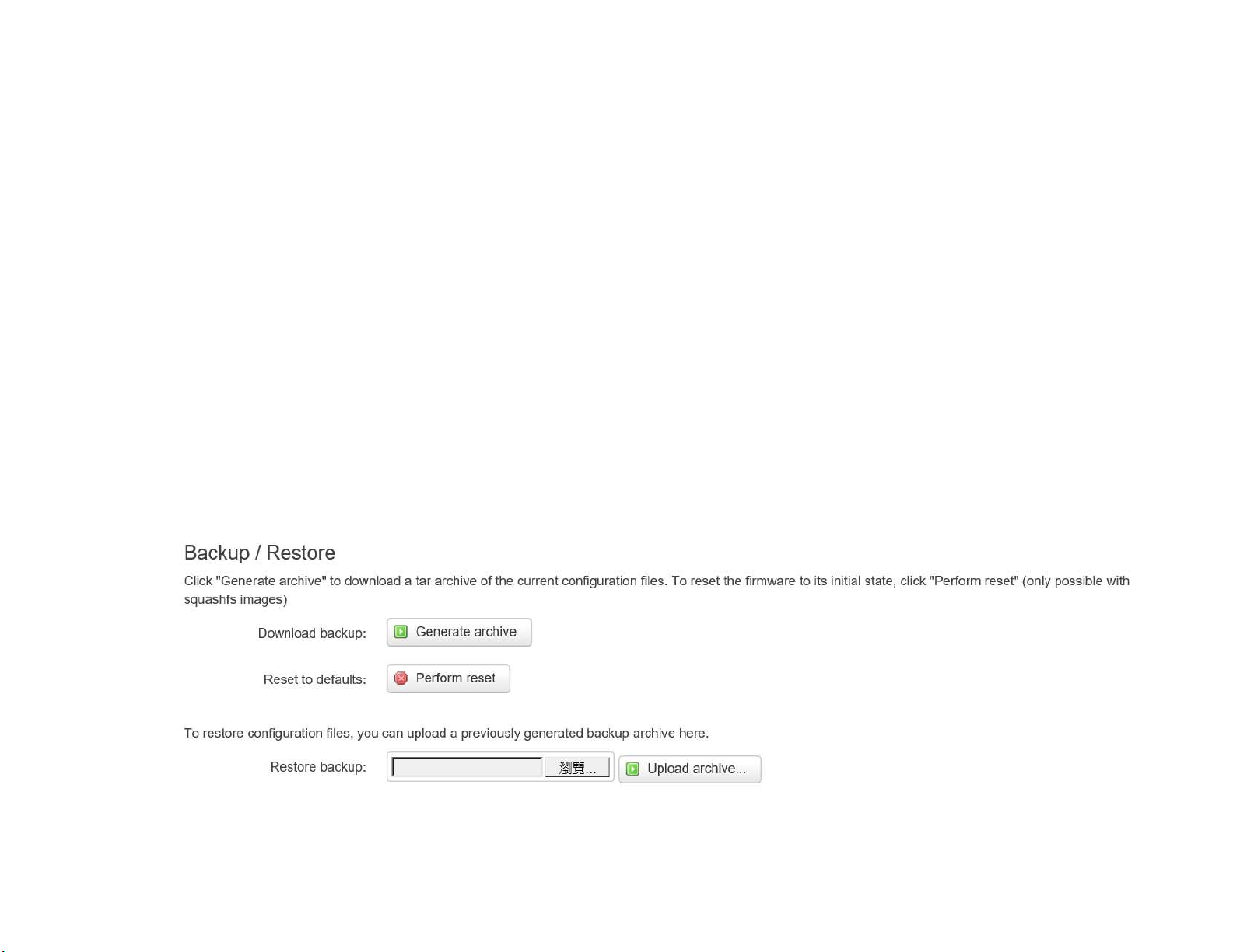
Backup/Restore
This page allows you to save the current device
configurations.Whenyousaveyourconfigurations,
youalsocanreloadthesavedconfigurationsintothe
devicethroughtheRestoreSavedSettingsfromafile
section.Ifextremeproblemsoccur,orifyouhaveset
theAPincorrectly,youcanusetheResetbuttoninthe
ReverttoFactoryDefaultSettingssectiontorestore
alltheconfigurationsoftheAPtotheoriginaldefault
settings.
Backup Setting: Click Export to save the current configured
settings.
Restore New Setting: To restore settings that have
beenpreviouslybackedup,clickBrowse,selectthe file, and
clickRestore.
Restore to Default: Click Reset button to restore the AP to its
factory default settings.
40
Page 42

User Setting
Thefunctionallowsyoutobackupthecurrentdevice
configurationsintotheAPasthedefaultvalue.If
extremeproblemsoccur,orifyouhavesettheAP
incorrectly,youcanpushtheResetbuttontorevertall
theconfigurationsoftheAPtotheuserdefault.
Note1:Aftersettingthecurrentsettingsasthedefault,youshouldclicktheRestore to Defaultonthe
webinterfaceforrevertingthesettingsintothefactorydefaultinsteadofpushingtheresetbutton.
Back Up Setting as Default: Click Backup to backup
theusersettingsyouwouldliketothedevice’smemory
forthedefaultsettings.
RestoretoUser
Default:Click
Restoretorestoreuser
settings to
the factory standard settings.
Note2:Pleasewritedownyouraccountandpasswordbeforesaving.Theusersettingswillnowbecome
the new default settings at the next successful login.
41
Page 43

Log
System Log
TheAPautomaticallylogs(records)eventsofpossible
interestinitsinternalmemory.Toviewthelogged
information,clicktheLoglinkundertheSystemManager
menu.Ifthereisnotenoughinternalmemorytologall
events,oldereventsaredeletedfromthelog.When
powereddownorrebooted,thelogwillbecleared.
42
Page 44
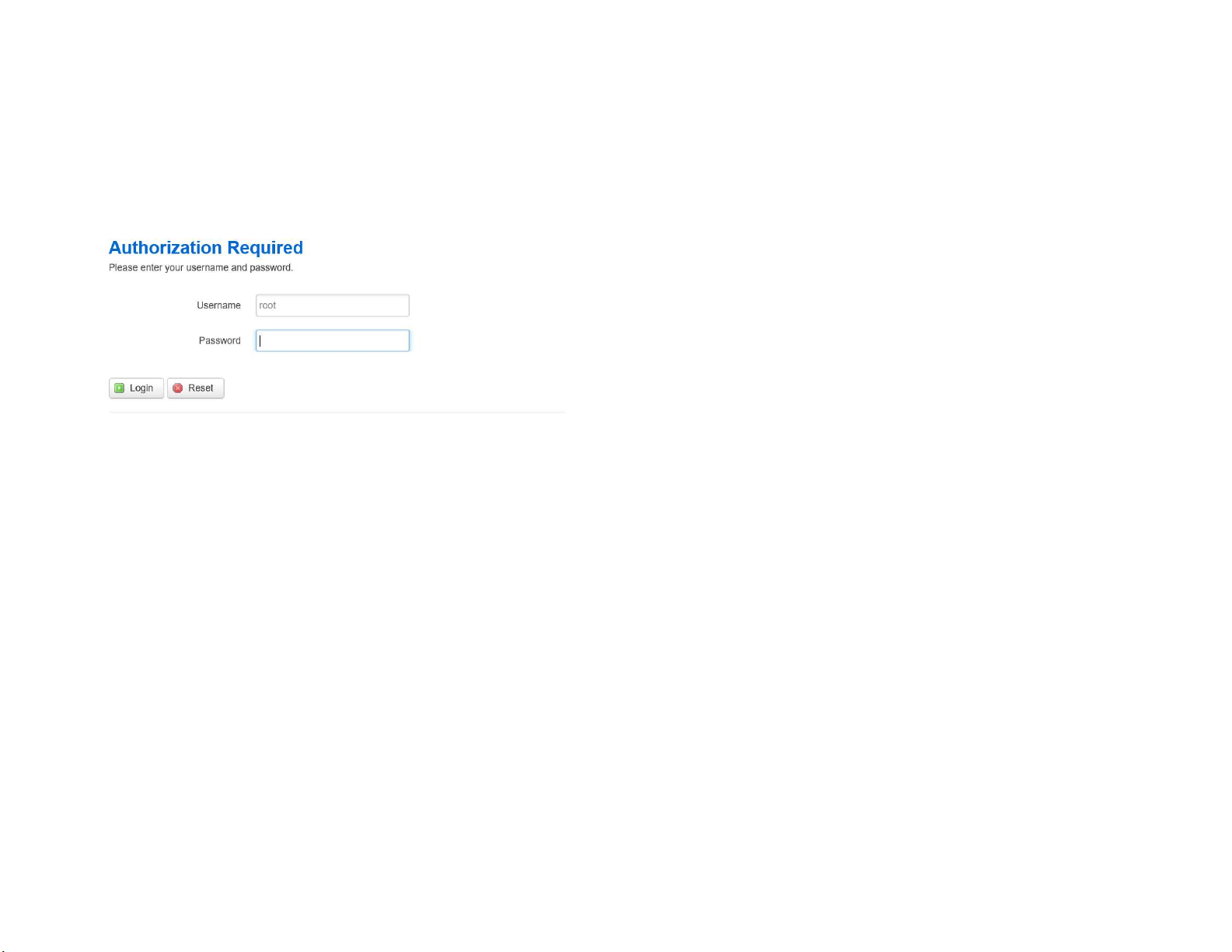
Logout
Logout:ClickLogout inManagementmenutologout.
Reset
Insomecircumstances,itmayberequiredtoforcethe
devicetoreboot.ClickonReset toreboottheAP.
Onceyouclickresetbutton,youwillseetheoptionsforreboot or restore this AP.
Rebootthedevice:Clickittorebootthisdevice.
RestoretoFactoryDefault:Clickittoresetthisdeviceto
RestoretoUserDefault:Clickittoresetthisdeviceto
factory defaultsetting.
userdefaultsettings.Forrealizingthesettingmethod,
43
Page 45

Appendix A - FCC Interference Statement
Federal Communication Commission Interference Statement
This equipment has been tested and found to comply with the limits for a Class B digital device, pursuant to Part 15 of the FCC Rules. These
limits are designed to provide reasonable protection against harmful interference in a residential installation. This equipment generates, uses,
and can radiate radio frequency energy and, if not installed and used in accordance with the instructions, may cause harmful interference to
radio communications. However, there is no guarantee that interference will not occur in a particular installation. If this equipment does cause
harmful interference to radio or television reception, which can be determined by turning the equipment off and on, the user is encouraged to
try to correct the interference by one of the following measures:
• Reorient or relocate the receiving antenna.
• Increase the separation between the equipment and receiver.
• Connect the equipment into an outlet on a circuit different from that to which the receiver is connected.
• Consult the dealer or an experienced radio/TV technician for help.
FCC Caution:
Any changes or modifications not expressly approved by the party responsible for compliance could void the user’s authority to
operate this equipment.
This device complies with Part 15 of the FCC Rules. Operation is subject to the following two conditions: (1) This device may not cause harmful
interference, and (2) this device must accept any interference received, including interference that may cause undesired operation.
IMPORTANT NOTE:
Radiation Exposure Statement
This equipment complies with FCC radiation exposure limits set forth for an uncontrolled environment. This equipment should be installed and
operated with a minimum distance of 20 cm between the radiator & your body.
44
Page 46

Appendix B - IC Interference Statement
Industry Canada Statement
This device complies with Canada license-exempt RSSs of the Industry Canada Rules. Operation is subject to the
following two conditions: (1) This device may not cause harmful interference, and (2) this device must accept any
interference received, including interference that may cause undesired operation.
Ce dispositif est conforme à la norme RSS Canada sans licence d’Industrie Canada applicable aux appareils radio exempts
de licence. Son fonctionnement est sujet aux deux conditions suivantes: (1) le dispositif ne doit pas produire de
brouillage préjudiciable, et (2) ce dispositif doit accepter tout brouillage reçu, y compris un brouillage susceptible de
provoquer un fonctionnement indésirable.
Caution:
(*) high-power radars are allocated as primary users (i.e. priority users) of the bands 5250-5350 MHz and 5650-5850 MHz and
that these radars could cause interference and/or damage to LE-LAN devices.
Avertissement:
(*) De plus, les utilisateurs devraient aussi être avisés que les utilisateurs de radars de haute puissance sont désignés utilisateurs
principaux (c.-à-d., qu’ils ont la priorité) pour les bandes 5250-5350 MHz et 5650-5850 MHz et que ces radars pourraient causer
du brouillage et/ou des dommages aux dispositifs LAN-EL.
Radiation Exposure Statement
This equipment complies with IC radiation exposure limits set forth for an uncontrolled environment. This equipment should be installed and operated
with minimum distance 21cm between the radiator & your body.
Déclaration d’exposition aux radiations:
45
Page 47

Cet équipement est conforme aux limites d'exposition aux rayonnements IC établies pour un environnement non contrôlé. Cet équipement
doit être installé et utilisé avec un minimum de 21cm de distance entre la source de rayonnement et votre corps.
Industry Canada Warning
This product meets the applicable Innovation, Science and Economic Development Canada technical specifications. Ce produit repond aux
specifications techniques applicables a l'innovation, Science et Developpement economique Canada.
46
Page 48

Appendix C - CE Interference Statement
Europe – EU Declaration of Conformity
• EN60950-1
Safety of Information Technology Equipment
• EN50385
Generic standard to demonstrate the compliance of electronic and electrical apparatus with the basic restrictions related to
human exposure to electromagnetic fields (0 Hz - 300 GHz)
• EN 300 328
Electromagnetic compatibility and Radio spectrum Matters (ERM); Wideband Transmission systems; Data transmission
equipment operating in the 2,4 GHz ISM band and using spread spectrum modulation techniques; Harmonized EN covering
essential requirements under article 3.2 of the R&TTE Directive
• EN 301 893
Broadband Radio Access Networks (BRAN); 5 GHz high performance RLAN; Harmonized EN covering essential requirements
of article 3.2 of the R&TTE Directive
• EN 301 489-1
Electromagnetic compatibility and Radio Spectrum Matters (ERM); ElectroMagnetic Compatibility (EMC) standard for radio
equipment and services; Part 1: Common technical requirements
• EN 301 489-17
Electromagnetic compatibility and Radio spectrum Matters (ERM); ElectroMagnetic Compatibility (EMC) standard for radio
equipment and services; Part 17: Specific conditions for 2,4 GHz wideband transmission systems and 5 GHz high performance
RLAN equipment
This device is a 5GHz wideband transmission system (transceiver), intended for use in all EU member states and EFTA countries,
except in France and Italy where restrictive use applies.
47
Page 49
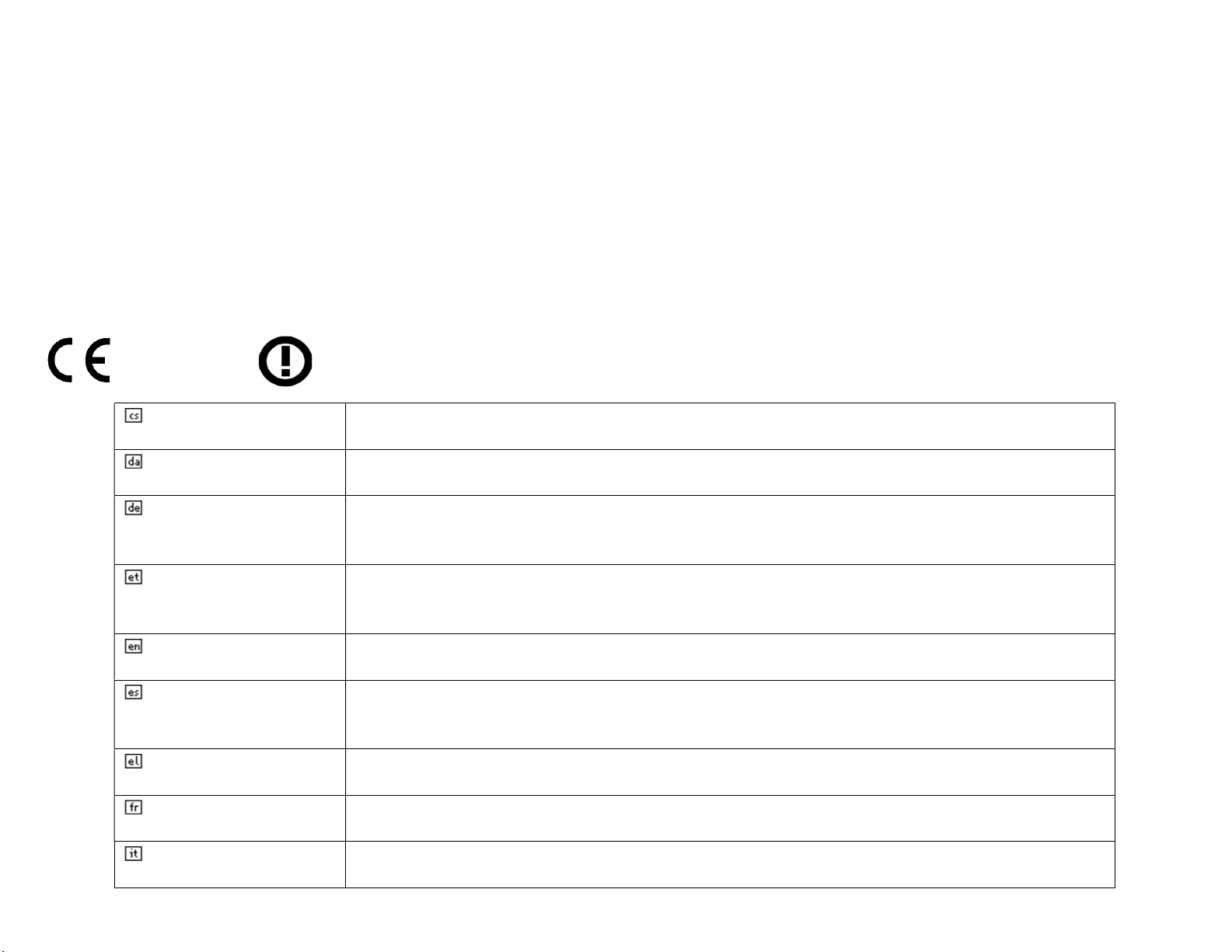
In Italy the end-user should apply for a license at the national spectrum authorities in order to obtain authorization to use the device for setting up outdoor radio links
dalšími příslušnými ustanoveními směrnice 1999/5/ES.
overholder de væsentlige krav og øvrige relevante krav i direktiv 1999/5/EF.
1999/5/EG befindet.
asjakohastele sätetele.
essential requirements and other
relevant provisions of Directive 1999/5/EC.
1999/5/CE.
ΠΡΟΣ ΤΙΣ ΟΥΣΙΩΔΕΙΣ ΑΠΑΙΤΗΣΕΙΣ ΚΑΙ ΤΙΣ ΛΟΙΠΕΣ ΣΧΕΤΙΚΕΣ ΔΙΑΤΑΞΕΙΣ ΤΗΣ ΟΔΗΓΙΑΣ 1999/5/ΕΚ.
exigences essentielles et aux autres dispositions pertinentes de la directive 1999/5/CE.
requisiti essenziali ed alle altre disposizioni pertinenti stabilite dalla direttiva 1999/5/CE.
and/or for supplying public access to telecommunications and/or network services.
This device may not be used for setting up outdoor radio links in France and in some areas the RF output power may be limited to 10 mW EIRP in the frequency range
of 2454 – 2483.5 MHz. For pdetailed information the end-user should contact the national spectrum authority in France.
This product will not exceed the frequency and the maximum EIRP transmitted power in EU are listed below:
2412-2472MHz: 20dBm
5470-5725MHz: 24dBm
0560
Česky [Czech] [Jméno výrobce] tímto prohlašuje, že tento [typ zařízení] je ve shodě se základními požadavky a
Dansk [Danish] Undertegnede [fabrikantens navn] erklærer herved, at følgende udstyr [udstyrets typebetegnelse]
Deutsch [German] Hiermit erklärt [Name des Herstellers], dass sich das Gerät [Gerätetyp] in Übereinstimmung mit den
grundlegenden Anforderungen und den übrigen einschlägigen Bestimmungen der Richtlinie
Eesti [Estonian] Käesolevaga kinnitab [tootja nimi = name of manufacturer] seadme [seadme tüüp = type of
equipment] vastavust direktiivi 1999/5/EÜ põhinõuetele ja nimetatud direktiivist tulenevatele teistele
English Hereby, [name of manufacturer], declares that this [type of equipment] is in compliance with the
Español [Spanish] Por medio de la presente [nombre del fabricante] declara que el [clase de equipo] cumple con los
requisitos esenciales y cualesquiera otras disposiciones aplicables o exigibles de la Directiva
Ελληνική [Greek] ΜΕ ΤΗΝ ΠΑΡΟΥΣΑ [name of manufacturer] ΔΗΛΩΝΕΙ ΟΤΙ [type of equipment] ΣΥΜΜΟΡΦΩΝΕΤΑΙ
Français [French] Par la présente [nom du fabricant] déclare que l'appareil [type d'appareil] est conforme aux
Italiano [Italian] Con la presente [nome del costruttore] dichiara che questo [tipo di apparecchio] è conforme ai
48
Page 50

Latviski [Latvian] Ar šo [name of manufacturer / izgatavotāja nosaukums] deklarē, ka [type o
saistītajiem noteikumiem.
1999/5/EB Direktyvos nuostatas.
met de essentiële eisen en de andere relevante bepalingen van r
ichtlijn 1999/5/EG.
essenzjali u ma provvedimenti oħrajn relevanti li hemm fid
-
Dirrettiva 1999/5/EC.
követelményeknek és az 1999/5/EC irányelv
egyéb elõírásainak
.
wymogami oraz pozostałymi stosownymi postanowieniami Dyrektywy 1999/5/EC.
essenciais e outras disposições da Di
rectiva 1999/5/CE.
relevantnimi določili direktive 1999/5/ES.
ustanovenia Smernice 1999/5/ES.
ehtojen mukainen.
egenskapskrav och övriga relevanta bestämmelser som framgår av direktiv 1999/
5/EG.
f equipment / iekārtas tips] atbilst Direktīvas 1999/5/EK būtiskajām prasībām un citiem ar to
Lietuvių [Lithuanian] Šiuo [manufacturer name] deklaruoja, kad šis [equipment type] atitinka esminius reikalavimus ir kitas
Nederlands [Dutch] Hierbij verklaart [naam van de fabrikant] dat het toestel [type van toestel] in overeenstemming is
Malti [Maltese] Hawnhekk, [isem tal-manifattur], jiddikjara li dan [il-mudel tal-prodott] jikkonforma mal-ħtiġijiet
Magyar [Hungarian] Alulírott, [gyártó neve] nyilatkozom, hogy a [... típus]megfelel a vonatkozó alapvetõ
Polski [Polish] Niniejszym [nazwa producenta] oświadcza, że [nazwa wyrobu] jest zgodny z zasadniczymi
Português [Portuguese] [Nome do fabricante] declara que este [tipo de equipamento] está conforme com os requisitos
Slovensko [Slovenian] [Ime proizvajalca] izjavlja, da je ta [tip opreme] v skladu z bistvenimi zahtevami in ostalimi
Slovensky [Slovak] [Meno výrobcu] týmto vyhlasuje, že [typ zariadenia]spĺňa základné požiadavky a všetky príslušné
Suomi [Finnish] [Valmistaja = manufacturer] vakuuttaa täten että [type of equipment = laitteen tyyppimerkintä]
tyyppinen laite on direktiivin 1999/5/EY oleellisten vaatimusten ja sitä koskevien direktiivin muiden
Svenska [Swedish] Härmed intygar [företag] att denna [utrustningstyp] står I överensstämmelse med de väsentliga
49
 Loading...