


A u t o - c h a n n e l - s e l e c t i ng
i n f r a r e d f u n c t i o n
P r o f e s s i o n a l w i re l e s s
micro phone with opt ional
m u l ti- c h anne l
m a nu al
U
H
F
2
0
0
o
p
t
i
o
n
a
l
c h
a
n
n
e l
s
A
u
t
o
-
c
h
a
n
n
e
l
-s
e
l
e
c
t
i
n
g
i
n
f
r
a
r
e
d
f
u
n
c
t
i
o
n
UHF
P r o f e s s i o n a l W i r e l e s s M i c r o p h o n e
USER GUIDE
P
r
o
f
e
s
s
i
o
n
a
l
w
i
r
el
e
s
s
m
i
c
r
o
p
h
o
n
e
Tha nkfulness on purchazin g our product s. Please
rea d this user guide carefully before using, just t o
ens ur e the mic ro ph onecould be perfouned op timally
Product: Wireless Microphone
Model: SNT-800

Profile
Welcome to our company! we
profe ssio nally produ ce UHF with
2 0 0 -c ha nn el f u n c ti on w i r el es s
microphone. They are adopted multi-
channel synthetic technology of DPLL
(digi ta l pha se -lock ed lo op ), and
pilotone technology. Within 50-meter
frequency band, preset 200 channels,
and then utilize infrared to select
channel and the system may pair
every of them and set automatically.
In this case, any microphone in the
system wold match the channel of
the receivers in the system. Especially
suitable for the occasion with several
sets being used simultaneously.
-1 -
640-689.75MHz
bro ad ba nd F M
200
250 KH z
±0.0 05 %
100 dB
±45K Hz
60H z- 18 KH z( 3±dB)
> 105 dB
≤0.5 %
about 100m (under the situation of no interruption
-10℃- - +50℃
sup er he te ro dyhe
110M Hz,1 0.7MHz
BNC /5 0Ω
12d Bu V (8 0d B S/N)
12- 32 dB uV
≥75d B
+10 d BV
Technology specification
-1 4-
System Parameter:
work f re qu en cy :
modula ti on m od e:
channe ls
channe l fr eq ue nc y:
Freque nc y st ab il it y:
dynami c bo un d:
max ex cu rs io n:
freque nc y re sp on se :
S/N
T.H.D
operat io n di st ar ce :
workin g en vi ro nm en t
temper at ur e:
Receiving machine index:
receiv in g ma ch in e mo de :
IF
antenn a re ce iv e:
sensit iv it iv e ad ju st ab le r ang:
sensit iv it ir e:
errati c co nt ro l:
max ou tp ut f re qu en cy
han d mi cr op ho ne has on i n bu il t helix
an ten n a t r a nsm itt er 1/4 war e-l e r g h
fla ge ll if or m antenna
Transmitter index:
antenn a:
output f re qu en cy :
errati c co nt ro l:
power su pp ly :
batter y vi ta li ty :
max frequency 30mw; mi n frequ ency 3mw
-60 dB
2 1.5 V al ka li ne batt er ie s
about 10 hours under normal frequency
trans mittion, abo ut 15 hours un der low
fre qu en cy t ra nsmitti on .

-2 -
do not ope ra te o ur b ab y of t he s it ua ti on s as a bo ve ! Only professi on al s ca n
disass em bl e an d as se mb le t he s ys te m!
War ni ng: Bew ar e of elec tr ic shoc k fi ne; mac hi ne must b e ke pt
away h um id cond it io ns!
Contions
plea se do not o pen up th e syste m.
tech nicia ns are al ways th e only pe rsons
to s ort o ut an y te chn ica l ope rat ion s.
strictly r ea de rs a re t ol d
Wel co me a nd t hank you for pu c ha zi ng o ur w ireless microph on e sy st em !r
Wit h yea rs expe ri enc e to pr od ucing wire le ss mi croph on e sys tem, ou r cre ws are
confident to say we ar e the ex per t of manufacturi ng wireless mi cro phone sy ste m.
Ou r p ro d u c t s a re sui t a b l e f or K TV roo m , k ar a o k e s ta g e a n d a ls o s ch o o l ,
sho wplac e, stad ium, an d so on . Our p roduc ts ar e conve nient t o ope ra te, a nd of
stably great quality. So t he y ar e wi de ly f av ou re d by o ur c us to me rs W e pr om is e
highly of first class qua lity, and also first cl ass ser vice . Our prof essi onal technician
cre w is al ways re ady to help yo u wit h any t echni ca l que stion s!
1. re ad th e use r guide -r ead c arefu lly abo ut sa fe ty an d man ip ulati on re qu ests.
2. ke ep th e man ip ulati on in tr oduct ions- pleas e keep this ma nual fo r fur ther ne ed
of safet y and m anipu la tio n reque sts.
3. beware of the warnings-please notice the warnings for the machine while operating.
4. fo llo w the den oteme nts-p lease f ollow t he de notem ents wh ile ope ratin g.
5. ac ce ss ional dev ic es -only acc es si onal de vi ce s from or ig in al produc er s of the
mac hin e are req uired .
6. hu mid it y cau ti ons -k eep t he mach ine awa y fro m hum id cond ic tio ns .
7. aeratio n-please keep the machine in well ventil ate d conditions at all time, there
sho uld b e at le ast 5cm clea ra nce a round t he de vi ce.
8. heat source-please keep the devices away from heat sources, including, radiator,
hea ter, s tov e, etc.
9. po wer s upply -p lea se util ize the labe ll ed vo ltage o n the d evice .
10. n o exp osed fi re sh ou ld be o n the d evi ce e.g. f lamin g can dl es.
11. plea se do not lit ter the bat teries, dis pos e the m into the appoi nte d place whe n
the y are f ull y used.
12. no li qu id o r we ig ht s sh ould be on th e de vi ce , no w at er d ri pping or spla sh in g
ont o lin t o the d evice .
13. t he de vice is also s uitab le in t orvie d zone, a nd va riabl e zone.
Problem & solution
-1 3-
Situation Solution
No voice; (si tuation: the receiv ing machine
RF display ca n not come on)
Chec k the trans mitter a nd the rece iving ma chine, se e
whether it is on the pl ay of "ON"
Chec k whethe r the "nega tivre" a nd the "pos itive" p ole
of the batter y is confusi ng.
Check the con necting sol tion of the rece iving machineu
and the aeria l.
Make su re that the re is no block b etwee the a erial and
the transm itter.
No voice; (situation: RF display is nomal; AF
display is nomal)
Check whether the voice re knob of the receiving machine
is on the lowest pla ce.
Check whether the connecting between the loudspeakers
of the receiv ing machine are nomal.
Check whet her the power of the transmi tter is open
Exchange the mike of the transmitter when it is necessary
No voice; (situation: RF display is nomal; AF
display is un-nomal)
Put through the transmitter, there is some noise
or some interruption noise in the receiving
signal
Check whet her the battery is tight eno ugh.
Elimina te the RF source of the disturb ance rearby.
Chec k the connec ting situ otion, if us ing githa r or other
mascial in sturment.
If both of the trans mitters are using the sam e frequency,
check it and clos e one lof them.
Maybe thesignal is too infirmnes s, adjust the place of the
antenna mo re it as near the transmitte r as possibl e.
Replace ot her channel.
There is some noise, after closing the
transmitter.
Adjust th e sensitivit y button of the trans mitter; the "SQ"
button.
Elimina te source of noise of RF.
Adju st the pla ce of the rec eiving m achine o r the plac e
of the antenn a over again
Can not open the transmitter
Change the ba ttery of the transmitt er.
While the showplace is moving. the voice from
the transmitter may get lost sometimes.
Adjust t he sensitivit y button of the tran smitter; the "SQ "
button.
Loca te the rec eiving m achine ov er again a nd hare the
"on-sho w" experiment, obs erre the RF display.
If you fi nd some voic e lost, tag th e point and av oid this
point when pe rforming.
Operation method and attentions
-1 2-
Operation method:
1.Con nect the au dio syst em well;
2. Set the volu me of the receiving machine and the louds peaker to mix;
3.Turn on the power of the audi o system from backing stage to backward stage;
4.Trun on the power of the tran smitter;
5. Adjust the audio effect of the audio system: firstly, adjust the volume of the receiving
mac hi ne t o th e mi ddle point, t ur n on t he m icrophone, ta lk d ir ec tl y forward the
microphone, fit the volume second ly, adjust the tone, volume contr oller carefully
and make the voice clea r, the volume suit abl e. Hdd the phone an d hare the "on
show" proless;
6. If the wir eless rece ivin g machine sys tem has some pro blem s. Please ref erence
this funcati on hare troubleshooting and solve the problem. If the problem is not in
the troubleshooting. Please onse the profe ssional to sowe it or hegotiate with the
franchiser;
7. After using, please turn off the power of the transmitter, than turn off the power of
al l the owdio system from backing stage word backword stage.
Attentions:
1. The erect location of the antenna effect the leleption effect of the leceivting machine
directly, so take attention to the installation method. If is the most important principle
that keep the distance between the microphone and the leceiving machine shortest.
2. Avoid putting the receiving machine hear the computer or other equipment which
can produce RF signal.
3. Avod putting the receiving machine in the orlop of the DB, exclude the installation
antenna from distance.
4. This re ceiving machine sys tem ca n fill 200 micr oph one at th e same ti me, an d it
could not disturb each other. If need to be adjusted different channels by professional.
5. When some wire less sy stems are used at the same ti me, ple as take attention to
the setting of "SQ" of the receiving machine. The lower the sensitive is the shorter
the capa city of distu rbance cou d be ! It is better that th e transmit ph one is short.l
It can save the electron ic and decr ease the jamming at the same time.
The are components in the wireless sound conducting system as below:
●
One wire le ss d ua l- ch an ne l RF r ec ei ve r.
two wire le ss m ic ro ph on es . th er e ar e fr om w ay s to choose (demo ns tr at ed b y
"system co nf ig ur at io n" b el ow )
●
two remova bl e at en na s.
●
System configuration
three wa ys t o co nf ig ur e mi cr op ho ne
●
two hand -m ic ro ph on es
●
One hand-microphone and lapel mike sender is opfional fro headset microphone
●
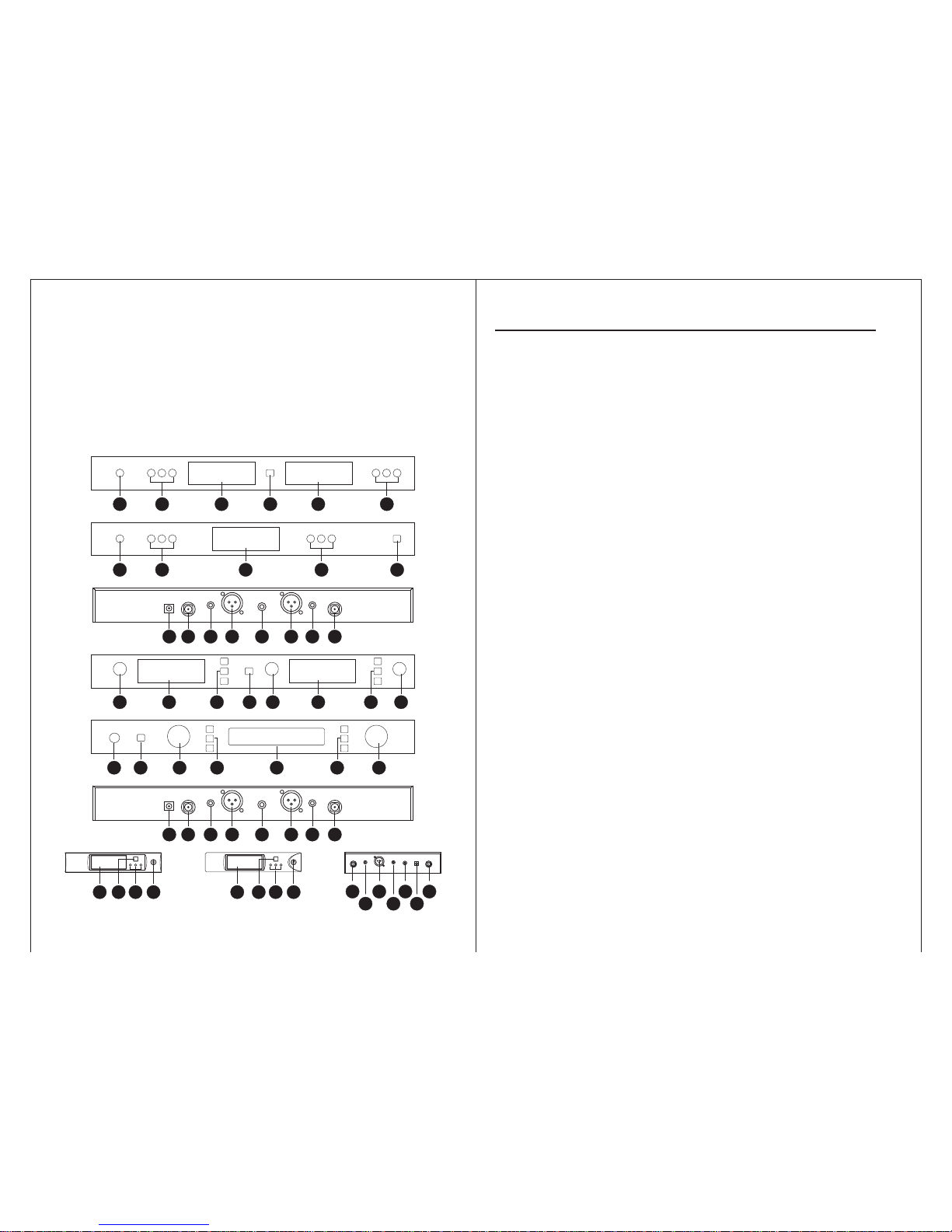
introductions for the wireless receiver
-3 -
52 43
8
9 107
6
8
7
52 43
1 2 3 44 1 52
1 23 45 4 1
5 3 24 42
5 34 2 4
7 1 9 10 9 716
7 8 9 10 9 786

Lapel transmitter funcation
-11 -
7. infr ar ed c ha nn el -s el ec ti ng window; work i n th e "S ET " bu tt on o f the receivi ng
machine, set the channel number to the tron smitter.
8. battery holde r: 2 1.5V alkaline batteries
9. funcation setting button: induding two "up" "down" chosing buttons and one menu
selection.
10. :high、low" fre quency emission chan ging but ton.
* Lapel transmitter operational guidance
oper ation meth od is the same as the handhe ld transmi tter's. It al so has "high" and
"low " frequenc y changing fu ncation .
* The batteries installation of lapel transmitter
1. pres s both sides of the battery cove r lightly and slide ou t, than you can ope n the
batte ry cage as below.
2. Pu t into 2 ne w 5 1.5 V al kalin e battery p lease e ns ure the b atter y po larit ie s are
well-set cfoll ow the polarity gai dance in the batter y hdder
3. Put on the battery cage cover.
(caution: please take out the batteries in the transmitter, if you willnot use the system
for lang time )
upsid e of batte ry coverthe
1. Volume knob
2. LED displanye r: chann el, mute, receive-ch annel freque ncy, radio frequency, etc
3. infrared channel-se lec t wind ow: send the channel pa rametre to the tra nsm itt er,
worki ng in "SET" button
chang e the menu state, press "SET" again to activate the setting.
5. Power on-off: Press the on-off, till LCD shows on the on-off 3sec. again, LCD shows
off, for the Power is off
4. three functi on keys : pree "SET",go to circular-selection menu, pre e " " " " to
▲
▲
5 10 15 20 25 30 35 40
-30 -25 -15 -10 -5 0 PEAK-20
RF
AF
FREQ.
CHAN.
MUTE
M
H
Z
1
2
3
4
6
5
Introduction for the LCD of the receiver
6. power socket: DC 12V 500mA power inputs socket, central electrode of the socket
connects to positive pole.
7. antenna jack
8.noise elim ina tio n cont rol : counter cloc k wise ly, to tur n down rece ive -se nsi tivity,
zoom in recei ve-distan ce, but str engthen anti-jamming function , rice vers a.
9. audio balance out: suita ble for long-distance connec tion, capable to knock down
the noise cau sed by line -connecti on.
10. audio mix out: send out one mixed signal by two.
-4 -
1. 8-level RF display: signal stren gth of the receivin g frequency
2. 8-level AF display: signal strength of the audio fre quency
3. frequenc y men u dis pla y: wh en th e ind ica tor i s on, current serv ice f req uen cy is
show by the last 6 digi ts
4. channel menu display: when the indicator is on, current service channel is shown.
5. mute display: when the indicator is on, frequency sign al is not received.
6. chan nel di splay: dyn amic display for the curr ent au to-sele cted atenn a chan nel,
shows channel A, means channel B.

1. Sound receive r: steel netting and sound hea d module
2.
LCD: service channel and battery
Lnfra red channel selectin g window: send the cha nnel par ameter to transmitte r,
working in the "SET" key of the receiver
3.
4. 3- ste p on-off: tu rned- off g oes d ownwa rds, mu te st ays mid dle, turne d-on go es
upward.
Specifications of the hand mike
Introduction for the hand microphone
Cauti on: if you want the microphone works mute during in use, had better set
the switch at middle rather than turning off, Swit h downwards to turn c
off after use .
5. pipe body: out built batteries, emission circuit board, inbuilt transmi tting antenn a
after body
6. battery cag e: 2 1.5V alkaline batteries (please take off the batteries, for not in use
a long time time)
-5 -
Cauti on: case of several products being use d in KV room, lower frequency is
recommtnded , less batt ery usin g and weake r radio-jamming)
1. input socket
2. power on-off: "ON" means power on, "OFF" means power off
3.indicator: when the switch goes to "ON", the indicator sparkles for once, which means
the battery wor ks wen , if it has no flare, th e battery is empt y, or not yet well -se t.
If the indica tor is on at all time , the batte ry is runni ng out.
ON OFF
BATT
LOW
1
2 3
4
5
6
7
8
10
9
4. transmitti ng antenna: 1/4 wave lengh flagellifo m antenna.
5. clip: fix the mini mike some where on waist-side, can be revolve d by 180 .
6. LCD: current service channel and battery volume.
r
°
functions of the lapel mike
Introduction of the lapel mike
-1 0-
A图
B图
A图
B图

Specifications of the handmike
-6 -
7. high-low RF switch (loca ted insi de the batt ery cage )
go to "ON", at the time outside power switch shaos off, the micropho ne is still
working at mute, but the transmi tting mike remains transmitting state.
8. lock key (lo cated in battery cage): used to lock the power on-off switch upw ards
Caut ion : This switc h is available to ke epi ng non -professio nal from shutti ng
do wn t he mi ke by m is tak e ch ann in g in us e (be ca us e u ne xp e ct ed
turned-off causes 2-3 sec delay)
Introduction of hand mike LCD
BA T
028 C
H
BA T
L a
BA T
LOC
BA T
OFF
1
2
3 4 5
(图 1) (图 2) (图 3) (图 4)
1. channel displ ay: curr ent service channel
2. 8-leve l battery volume display: when the last 2-le vel starts displa ying, full battery
is required.
3. please put on full-chang ed batte ry when dis play as pic·2 .
4. when lock key is on with power switch off, display, as pic·3, which mean s
transmitter is locked, mute funct ion is on while power off
Receiving machine channel -selecting and other special
functions of the the receiver.
-9 -
* switch frequency display to channel display
1. tur n on the po wde r of the re cei ving mach ine : pres s the po wde r butt on and LCD
light is brig ht
2. Press "SET" button for once, appear picture 8
4. Press" SET" to ensure, finish the funlation of unlocking.
3. Press " " button, appea r pictur e T and flash
▲
RF
AF
5
-30 -25 -20 -15 -10 -5 0 PEAK
10 15 20 25 30 35 40
MUTE
M
H
Z
(图 7) (图 8)
RF
AF
5
-30 -25 -20 -15 -10 -5 0 PEAK
10 15 20 25 30 35 40
MUTE
M
H
Z
▲
1. turn on th e pow der of the r ece iving mach ine : pre ss th e pow der button the LCD
light is brig ht.
2. Press "SET" continu ously for tuile. Show it picture 4
3. Press " " button, appea r "pictu re 3" and flash
4. Pr es s" S ET " to e ns ur e, press it aga in a nd t ha n it w il l le ture to the s it ua ti on o f
frequency disp lay.
* lock the choosen channel
This locked funcation can be used when the lece iving machine is adjusted.
when the lock ed funcation is on, ht e three funcation buttoin in the lecei ving
machi ne ponel would be lock ed, in order to prevent inonpr ofessiona l presons
mista ke work.
Operortion steps below:
1. turn on the power of receiving mochine: press the power button, LCD light is bright.
2. Press "SET" continuously for three times, appear picture 7
3. Press the " " button to ensure and finish the fucation of locked channel.
▲
* turn off the locked funcation
A图
B图

-7 -
Specifications of the hand mike
manual for handheld transmitter
channel battery volume. If service channel needs to change, receiver's channel
shou ld b e ch an ged f ir s ly. th en aim up t he i nf ra red w in do ws o f tr ans mi tt er a nd t
receiver, and then operate channel-selecting by hitting "SET" in receiver, klew channel
para meters will be sent to the trans mitter.
manual for handheld transmitter
1. hold the column on upside, press he battery cover on upside, which is found right t
below the sphere protect-net slide down the battery cover, the battery cage will expose.
Caution: do not misset polarities, it may alamage internal electronic components
of transmitter
2. Put two new 1.5V alkali ne battery on. make sure polar ities are well set
5 10 15 20 25 30 35 40
-30 -25 -15 -10 -5 0 PEAK-20
RF
AF
CHAN.
MUTE
M
H
Z
5 10 15 20 25 30 35 40
-30 -25 -15 -10 -5 0 PEAK-20
RF
AF
FREQ.
CHAN.
MUTE
M
H
Z
5 10 15 20 25 30 35 40
-30 -25 -15 -10 -5 0 PEAK-20
RF
AF
FREQ.
CHAN.
MUTE
M
H
Z
(图 4) (图 5)
(图 6)
(图 1) (图 2)
(图 3)
5 10 15 20 25 30 35 40
-30 -25 -15 -10 -5 0 PEAK-20
RF
AF
CHAN.
MUTE
M
H
Z
5 10 15 20 25 30 35 40
-30 -25 -15 -10 -5 0 PEAK-20
RF
AF
CHAN.
MUTE
M
H
Z
5 10 15 20 25 30 35 40
-30 -25 -15 -10 -5 0 PEAK-20
RF
AF
CHAN.
MUTE
M
H
Z
Channel-selecting and other special functions of the receiver
-8 -
select channel autometically with infrared
1. turn on he receiver: press the po wer on-o ff and hold on till LCD lights up.t
the selection.
3. turn on the mike, press "SET", LCD will display like pic·1, then aim the cha nnel-
selec ting window of the mike of ACT □ window of the recei ver, till LCD display s
like pic·2, cha nnel is wel l-selecte d.
4. display like pic·3, which means infrared is sent but not yet selected by any channel,
Switch channel display to frequency display
1. turn on he receiver: press the po wer on-o ff and hold on till LCD lights up.t
2. press "SET" twice, display like pic·4.
4. press "SET" to ensure, press again, go back to frequency display state, like pic·6.
2. select channel (or frequency) by pressing " " or " "then press "SET" to ensure
▲
▲
so press " " to select channel one more time.
▲
3. press " " ,sparkle like pic·5.
▲

FCC Statement
Changes or modifications not expressly approved by the party responsible
for compliance could void the user's authority to operate the equipment.
This equipment has been tested and found to comply with the limits for a
Class B digital device, pursuant to Part 15 of the FCC Rules. These limits
are designed to provide reasonable protection against harmful interference
in a residential installation. This equipment generates uses and can radiate
radio frequency energy and, if not installed and used in accordance with the
instructions, may cause harmful interference to radio communications.
However, there is no guarantee that interference will not occur in a
particular installation. If this equipment does cause harmful interference to
radio or television reception, which can be determined by turning the
equipment off and on, the user is encouraged to try to correct the
interference by one or more of the following measures:
-- Reorient or relocate the receiving antenna.
-- Increase the separation between the equipment and receiver.
-- Connect the equipment into an outlet on a circuit different from that to
which the receiver is connected.
-- Consult the dealer or an experienced radio/TV technician for help
This device complies with part 15 of the FCC rules. Operation is subject to
the following two conditions (1)this device may not cause harmful
interference, and (2) this device must accept any interference received,
including interference that may cause undesired operation
 Loading...