

Page 1
800 243 4844
orders@empireindustries.com
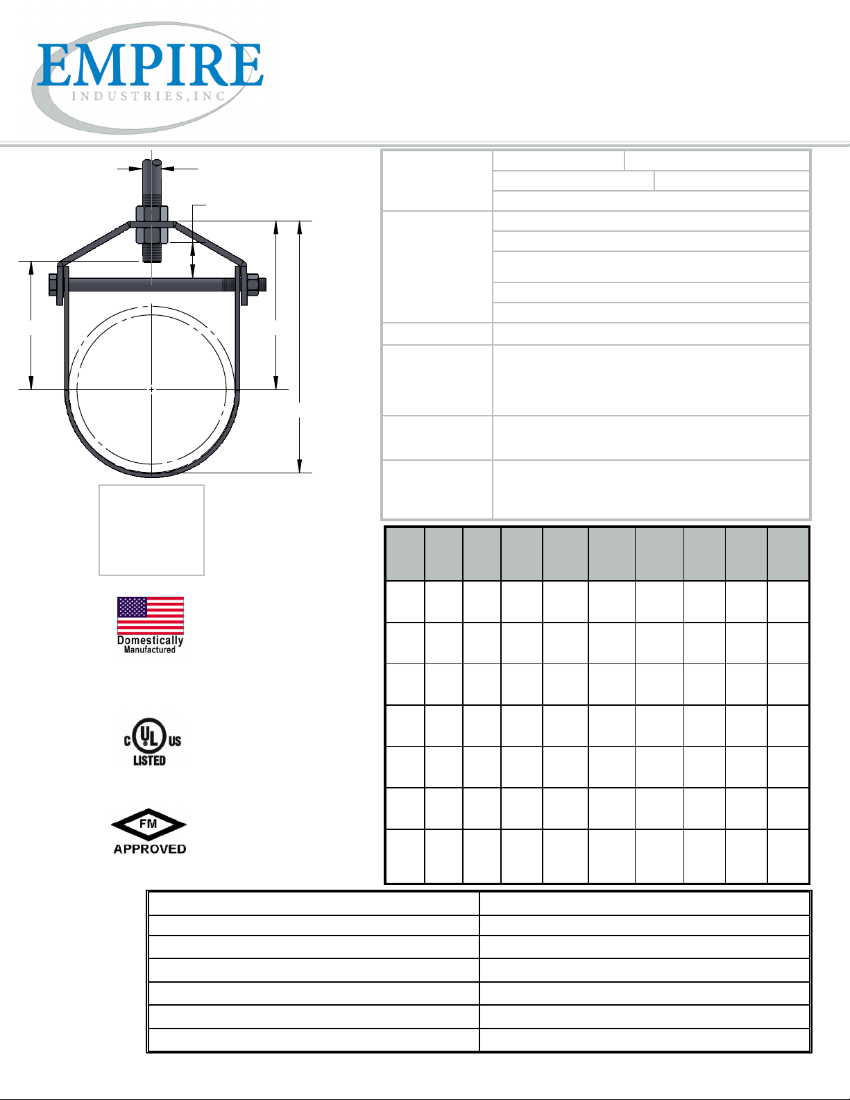
FIG. 11
clevis hanger, standard
C
OF PIPE
L
“E” dimension includes
exposed rod threads
beyond bottom of the
hex nut. Exposed rod
thread dimension is
equal to the diameter of
the rod used.
excluding:
11GI
11GIFL
11HDGI
excluding:
11RR
excluding:
11SS, 11SX & 11RR
A
F
Materials/Finishes Plain Carbon Steel (11B) Electro-Galvanized (11G)
Hot-Dip Galvanized (11HDG) T-304 Stainless (11SS)
T-316 Stainless (11SX)
Variants: Pipe Gard (11PG) - Please contact factory for details.
Electro-Galvanized, Imported: 1/2” - 12” (11GI)
Electro-Galvanized, 3/16” thick Felt-Lined, Imported: 1/2” - 8”
(11GIFL)
Hot-Dip Galvanized, Imported: 2”-3”, 4”-6”, 8”-12” (11HDGI)
Clevis Standard with Reduced Rod (11RR)
B E
Service: Designed for the suspension of non-insulated, stationary pipe lines.
Approvals: U.L. - U.L.C. listed (sizes 2-1/2” - 8” excluding 7”) and FM approved
(3/4” - 2” galv only. 2-1/2” - 8” plain and galv.). Complies with
Federal Specication WW-H-171-E (Type# 1), A-A-1192 A (Type#
1) and Manufacturers’ Standardization Society MSS SP-58 and SP-69
C
(Type# 1). Approvals do not apply to 11RR.
Ordering: Specify gure number, material, nish type and pipe size.
For 11RR, Specify gure number, material, nish type, pipe size and
rod size.
Notes:
For sizes 20” and larger a spacer sleeve is added over the cross
bolt. Upper locknut must be tightened securely to assure proper
hanger performance. Stainless steel hangers are recommended for applications where protection from a corrosive environment is required.
PIPE
PIPEODBO LT A B C E F WGT
SIZE
1/2
3/4
1
1-1/4
1-1/2
2
2-1/2
3
3-1/2
4
5
6
7
8
10
12
14
16
18
20
24
30
0.840
1.050
1.315
1.660
1.900
2.375
2.875
3.500
4.000
4.500
5.563
6.625
7.625
8.625
10.750
12.750
14.000
16.000
18.000
20.000
24.000
30.000
1/4
1/4
1/4
1/4
1/4
1/4
5/16
5/16
5/16
3/8
1/2
1/2
1/2
5/8
3/4
3/4
7/8
1
1
1-1/4
1-1/4
1-1/4
3/8
3/8
3/8
3/8
3/8
3/8
1/2
1/2
1/2
5/8
5/8
3/4
3/4
3/4
7/8
7/8
1
1
1
1-1/4
1-1/4
1-1/4
1-11/16
1-11/16
2-1/16
2-1/2
2-7/8
3-5/16
4-1/2
4-3/4
5-7/8
5-15/16
5-11/16
6-13/16
7-13/16
8-1/16
10
11-9/16
12-9/16
13-15/16
16
17-1/2
19-3/4
24-1/8
2-1/16
2-9/16
2-11/16
3-3/16
3-11/16
4-7/16
5-7/8
6-1/2
7-15/16
8-3/16
8-7/16
10-1/8
11-5/8
12-7/16
15-7/16
18
19-9/16
21-15/16
25
27-1/2
31-3/4
39-1/8
5/16
1-5/16
1-1/4
1-11/16
2-1/16
2-1/2
3-3/8
3-11/16
4-13/16
4-9/16
4-5/16
5-3/16
6-3/16
6-1/4
8
9-9/16
10-9/16
11-15/16
13-7/8
15-1/8
17-3/8
21-1/2
EACH
(LBS)
7/16
7/16
5/8
7/8
1-1/16
1-1/4
1-15/16
1-3/4
2-9/16
2-1/8
1-7/16
1-3/4
2
1-7/8
2-1/4
2-13/16
2-9/16
2-13/16
3-3/4
3-3/4
4
4-3/4
0.18
0.18
0.22
0.26
0.34
0.38
0.86
0.96
1.14
1.26
2.04
2.80
3.24
4.46
8.06
10.34
14.80
21.00
24.40
47.00
54.00
69.50
MAX
REC
LOAD
(LBS)
730
730
730
730
730
730
1130
1130
1350
1430
1430
1940
2000
2000
3600
3800
4200
4600
4800
4800
4800
6000
PROJECT INFORMATION APPROVAL STAMP
Project: Notes:
Address:
Contractor:
Engineer:
Date:
Approved Approved as Noted Not Approved
 Loading...