

Empire Heating Systems SR-10T-3, SR-18T-3, SR-30T-3 Installation Instructions And Owner's Manual
INSTALLATION INSTRUCTIONS
AND
OWNER’S MANUAL
UNVENTED
ROOM HEATER
MODELS
SR-10T-3 SR-18T-3 SR-30T-3
SR-30T SHOWN
Installer: Leave this manual with the appliance.
Consumer: Retain this manual for future reference.
WARNING: If the information in these instructions
are not followed exactly, a re or explosion may
result causing property damage, personal injury or
loss of life.
— Do not store or use gasoline or other ammable
vapors and liquids in the vicinity of this or any
other appliance.
— WHAT TO DO IF YOU SMELL GAS
• Do not try to light any appliance.
• Do not touch any electrical switch; do not use
any phone in your building.
• Immediately call your gas supplier from a
neighbor’s phone. Follow the gas supplier’s
instructions.
• If you cannot reach your gas supplier, call the
re department.
— Installation and service must be performed by a
qualied installer, service agency or the gas supplier.
This is an unvented gas-red heater. It uses air (oxygen) from the room in which it is installed. Provisions
for adequate combustion and ventilation air must be
provided. Refer to page 6.
WARNING: If not installed, operated and maintained
in accordance with the manufacturer’s instructions,
this product could expose you to substances in fuel
or from fuel combustion which can cause death or
serious illness.
WATER VAPOR: A BY-PRODUCT OF UNVENTED ROOM
HEATERS
Water vapor is a by-product of gas combustion. An
unvented room heater produces approximately one (1)
ounce (30ml) of water for every 1,000 BTU’s (.3KW’s)
of gas input per hour. Refer to page 6.
Page 1

TABLE OF CONTENTS
SECTION PAGE
Important Safety Information ......................................................................... 3
Safety Information for Users of LP Gas ........................................................4
Introduction ...................................................................................................5
Specications ................................................................................................5
Water Vapor: A By-Product of Unvented Room Heaters ...............................6
Provisions for Adequate Combustion and Ventilation Air ..............................6
Gas Supply .................................................................................................... 7
SR-10T Clearances ......................................................................................8
SR-18T Clearances ......................................................................................9
SR-30T Clearances ......................................................................................9
Wall Mount Installation ...........................................................................10-11
Optional Floor Stand Installation ................................................................. 11
Lighting Instructions ...................................................................................12
Main Burner Flame Characteristics ............................................................ 13
Pilot Flame Characteristics ........................................................................14
Thermostat Operation .................................................................................14
Appliance Maintenance ............................................................................... 15
Troubleshooting ...........................................................................................16
SR-10T Parts List .......................................................................................16
SR-18T and SR-30T Parts List ...................................................................17
SR-10T Parts View .....................................................................................18
SR-18T Parts View .....................................................................................19
SR-30T Parts View .....................................................................................20
Optional Blower Installation Instructions ...............................................21-22
Master Parts Distributor List ........................................................................ 23
How To Order Repair Parts .........................................................................23
Warranty ......................................................................................................24
16941-8-0314Page 2
IMPORTANT SAFETY INFORMATION
THIS IS A HEATING APPLIANCE
DO NOT OPERATE THIS APPLIANCE WITHOUT FRONT PANEL INSTALLED.
DANGER: Indicates a hazardous situation which, if not
avoided, will result in death or serious injury.
WARNING: Indicates a hazardous situation which, if
not avoided, could result in death or serious injury.
CAUTION: Indicates a hazardous situation which, if
not avoided, could result in minor or moderate injury.
NOTICE: Addresses practices not related to personal in-
jury.
• An unvented room heater having an input rating of
more than 6,000 Btu per hour shall not be installed in a
bathroom.
• An unvented room heater having an input rating of more
than 10,000 Btu per hour shall not be installed in a bedroom
or bathroom.
• Due to high temperatures, the appliance should be located
out of trafc and away from furniture and draperies.
• Children and adults should be alerted to the hazard of
high surface temperature and should stay away to avoid
burns or clothing ignition.
• Young children should be carefully supervised when they
are in the same room with the appliance.
• Do not place clothing or other ammable material on or
near the appliance.
• Due to high surface temperatures, keep children, clothing
and furniture away.
• Installation and repair should be done by a QUALIFIED
SERVICE PERSON. The appliance should be inspected
before use and at least annually by a professional service
person. More frequent cleaning may be required due to
excessive lint from carpeting, bedding materials, etc. It
is imperative that control compartments, burners and
circulating air passageways of the appliance be kept
clean.
• DO NOT use this room heater if any part has been under
water. Immediately call a qualied service technician to
inspect the room heater and to replace any part of the
control system and any gas control which has been under
water.
• WARNING: ANY CHANGE TO THIS HEATER OR ITS
CONTROLS CAN BE DANGEROUS.
Any safety screen or guard removed for servicing
an appliance must be replaced prior to operating the
heater.
• Keep appliance area clear and free from combustible
materials, gasoline and other ammable vapors and
liquids
• WARNING: Failure to keep the primary air opening(s)
of the burner(s) clean may result in sooting and property
damage.
When used without adequate combustion and ventilation
air, heater may give off CARBON MONOXIDE, an odorless,
poisonous gas.
Do not install heater until all necessary provisions are
made for combustion and ventilation air. Consult the written instructions provided with the heater for information
concerning combustion and ventilation air. In the absence
of instructions, refer to the National Fuel Gas Code, ANSI
Z223.1/NFPA 54, Air for Combustion and Ventilation, or
applicable local codes.
This heater is equipped with a PILOT LIGHT SAFETY SYSTEM designed to turn off the heater if not enough fresh air
is available.
DO NOT TAMPER WITH PILOT LIGHT SAFETY SYSTEM!
If heater shuts off, do not relight until you provide fresh air.
If heater keeps shutting off, have it serviced. Keep burner and
control compartment clean.
16941-8-0314 Page 3
WARNING
CARBON MONOXIDE POISONING MAY LEAD TO
DEATH.
Early signs of carbon monoxide poisoning resemble the u,
with headache, dizziness and/or nausea. If you have these
signs, heater may not be working properly. Get fresh air at
once! Have heater serviced.
Some people — pregnant women, persons with heart or lung
disease, anemia, those under the inuence of alcohol, those
at high altitudes — are more affected by carbon monoxide
than others.
The pilot light safety system senses the depletion of oxygen
at its location. If this heater is installed in a structure having a high vertical dimension, the possibility exists that the
oxygen supply at the higher levels will be less than that at
the heater. In this type of application, a fan to circulate the
structure air will minimize this effect. The use of this fan will
also improve the comfort level in the structure. When a fan is
used to circulate air, it should be located so that the air ow
is not directed at the burner.

SAFETY INFORMATION FOR USERS OF LP-GAS
Propane (LP-Gas) is a ammable gas which can cause res
and explosions. In its natural state, propane is odorless and
colorless. You may not know all the following safety precautions
which can protect both you and your family from an accident.
Read them carefully now, then review them point by point
with the members of your household. Someday when there
may not be a minute to lose, everyone’s safety will depend
on knowing exactly what to do. If, after reading the following
information, you feel you still need more information, please
contact your gas supplier.
LP-GAS WARNING ODOR
If a gas leak happens, you should be able to smell the gas because of the odorant put in the LP-Gas.
That’s your signal to go into immediate action!
• Do not operate electric switches, light matches, use your
phone. Do not do anything that could ignite the gas.
• Get everyone out of the building, vehicle, trailer, or area. Do
that IMMEDIATELY.
• Close all gas tank or cylinder supply valves.
• LP-Gas is heavier than air and may settle in low areas such
as basements. When you have reason to suspect a gas leak,
keep out of basements and other low areas. Stay out until
reghters declare them to be safe.
• Use your neighbor’s phone and call a trained LP-Gas service
person and the re department. Even though you may not
continue to smell gas, do not turn on the gas again. Do not
re-enter the building, vehicle, trailer, or area.
• Finally, let the service man and reghters check for escaped
gas. Have them air out the area before you return. Properly
trained LP-Gas service people should repair the leak, then
check and relight the gas appliance for you.
NO ODOR DETECTED - ODOR FADE
Some people cannot smell well. Some people cannot smell the
odor of the chemical put into the gas. You must nd out if you
can smell the odorant in propane. Smoking can decrease your
ability to smell. Being around an odor for a time can affect your
sensitivity or ability to detect that odor. Sometimes other odors in
the area mask the gas odor. People may not smell the gas odor
or their minds are on something else. Thinking about smelling a
gas odor can make it easier to smell.
The odorant in LP-gas is colorless, and it can fade under some
circumstances. For example, if there is an underground leak, the
movement of the gas through soil can lter the odorant. Odorants
in LP-Gas also are subject to oxidation. This fading can occur if
there is rust inside the storage tank or in iron gas pipes.
The odorant in escaped gas can adsorb or absorb onto or into walls,
masonry and other materials and fabrics in a room. That will take
some of the odorant out of the gas, reducing its odor intensity.
LP-Gas may stratify in a closed area, and the odor intensity could
vary at different levels. Since it is heavier than air, there may be
more odor at lower levels. Always be sensitive to the slightest gas
odor. If you detect any odor, treat it as a serious leak. Immediately
go into action as instructed earlier.
• Learn to recognize the odor of LP-gas. Your local LP-Gas
Dealer can give you a “Scratch and Sniff” pamphlet. Use it to
nd out what the propane odor smells like. If you suspect that
your LP-Gas has a weak or abnormal odor, call your LP-Gas
Dealer.
• If you are not qualied, do not light pilot lights, perform service,
or make adjustments to appliances on the LP-Gas system. If
you are qualied, consciously think about the odor of LP-Gas
prior to and while lighting pilot lights or performing service or
making adjustments.
• Sometimes a basement or a closed-up house has a musty
smell that can cover up the LP-Gas odor. Do not try to light
pilot lights, perform service, or make adjustments in an area
where the conditions are such that you may not detect the
odor if there has been a leak of LP-Gas.
• Odor fade, due to oxidation by rust or adsorption on walls of
new cylinders and tanks, is possible. Therefore, people should
be particularly alert and careful when new tanks or cylinders
are placed in service. Odor fade can occur in new tanks, or
reinstalled old tanks, if they are lled and allowed to set too
long before relling. Cylinders and tanks which have been
out of service for a time may develop internal rust which will
SOME POINTS TO REMEMBER
cause odor fade. If such conditions are suspected to exist,
a periodic sniff test of the gas is advisable. If you have any
question about the gas odor, call your LP-gas dealer. A
periodic sniff test of the LP-gas is a good safety measure
under any condition.
• If, at any time, you do not smell the LP-Gas odorant and you
think you should, assume you have a leak. Then take the same
immediate action recommended above for the occasion when
you do detect the odorized LP-Gas.
• If you experience a complete “gas out,” (the container is under no vapor pressure), turn the tank valve off immediately.
If the container valve is left on, the container may draw in
some air through openings such as pilot light orices. If this
occurs, some new internal rusting could occur. If the valve is
left open, then treat the container as a new tank. Always be
sure your container is under vapor pressure by turning it off
at the container before it goes completely empty or having it
relled before it is completely empty.
16941-8-0314Page 4
INTRODUCTION
Instructions to Installer
1. Installer must leave instruction manual with owner after
installation.
2. Installer must have owner ll out and mail warranty card supplied
with unvented room heater.
3. Installer should show owner how to start and operate unvented
room heater.
Always consult your local Building Department regarding regulations,
codes or ordinances which apply to the installation of an unvented
room heater.
This appliance may be installed in an aftermarket* permanently
located, manufactured (mobile) home, where not prohibited by
state or local codes.
*Aftermarket: Completion of sale, not for purpose of resale, from
the manufacturer.
This appliance is only for use with the type of gas indicated on the
rating plate. This appliance is not convertible for use with other
gases.
General Information
This appliance is design certied in accordance with American
National Standards Institute Z21.11.2 by the Canadian Standards
Association Laboratories as an Unvented Room Heater and shall
be installed according to these instructions.
Any alteration of the original design, installed other than as
shown in these instructions or use with a type of gas not
shown on the rating plate is the responsibility of the person
and company making the change.
Important
All correspondence should refer to complete Model Number, Serial
Number and type of gas.
Well Head Gas Installations
Some natural gas utilities use “well head” gas. This may affect the
Btu output of the unit. Contact the gas company for the heating value.
Contact the manufacturer or your gas company before changing
spud/orice size.
Qualied Installing Agency
Installation and replacement of gas piping, gas utilization equipment
or accessories and repair and servicing of equipment shall be
performed only by a qualied agency. The term “qualied agency”
means any individual, rm, corporation, or company that either in
person or through a representative is engaged in and is responsible
for (a) the installation, testing, or replacement of gas piping or (b) the
connection, installation, testing, repair, or servicing of equipment;
that is experienced in such work; that is familiar with all precautions
required, and that has complied with all the requirements of the
authority having jurisdiction.
State of Massachusetts: The installation must be made
by a licensed plumber or gas tter in the Commonwealth of
Massachusetts.
Sellers of unvented propane or natural gas-red supplemental
room heaters shall provide to each purchaser a copy of 527 CMR
30 upon sale of the unit.
In the State of Massachusetts, unvented propane and natural
gas-red space heaters shall be prohibited in bedrooms and
bathrooms.
The installation must conform with local codes or, in the absence
of local codes, with the National Fuel Gas Code, ANSI Z223.1
(latest edition).*
*Available from the American National Standards Institute, Inc., 11
West 42nd St., New York, N.Y. 10036.
High Altitudes
For altitudes/elevations above 2,000 feet (610m) ratings should be
reduced at the rate of 4 percent for each 1,000 feet (305m) above
sea level. Contact the manufacturer or your gas company before
changing spud/orice size.
Model SR-10T SR-18T SR-30T
Input BTU/HR (KW/H) Five Plaques - - 30,000 (8.8)
BTU/HR (KW/H) Three Plaques - 18,000 (5.3) BTU/HR (KW/H) One Plaque 10,000 (2.9) - Height 22” (559mm) 22” (559mm) 22” (559mm)
Width 11 7/8” (302mm) 18” (457mm) 24 1/8” (613mm)
Depth 6 1/2” (165mm) 6 1/2” (165mm) 6 1/2” (165mm)
Gas Inlet 3/8” (10mm) 3/8” (10mm) 3/8” (10mm)
Accessories
Blower - SRB-18T SRB-30T
Floor Stand SRS-10* SRS-18 SRS-30
*Floor stand can not be used in a bedroom installation. SR-10T must be wall mounted in a bedroom installation. The bathroom or bedroom
must be an unconned space.
16941-8-0314 Page 5
SPECIFICATIONS

WATER VAPOR: A BY-PRODUCT OF UNVENTED ROOM HEATERS
Water vapor is a by-product of gas combustion. An unvented room
heater produces approximately one (1) ounce (30ml) of water for
every 1,000 BTU’s (.3KW’s) of gas input per hour.
Unvented room heaters must be used as supplemental heat (a
room) rather than a primary heat source (an entire house). In most
supplemental heat applications, the water vapor does not create a
problem. In most applications, the water vapor enhances the low
humidity atmosphere experienced during cold weather.
The following steps will help insure that water vapor does not
become a problem.
1. Be sure the heater is sized properly for the application, including
ample combustion air and circulation air.
2. If high humidity is experienced, a dehumidier may be used to
help lower the water vapor content of the air.
3. Do not use an unvented room heater as the primary heat source
(an entire house).
PROVISIONS FOR ADEQUATE COMBUSTION & VENTILATION AIR
This heater shall not be installed in a conned space or unusually
tight construction unless provisions are provided for adequate
combustion and ventilation air.
A conned space is an area with volume less than 50 cubic feet per
1,000 Btuh of the combined input rates of all appliances drawing
combustion air from that space. Small areas such as equipment
rooms are conned spaces. Furnaces installed in a conned space
which supply heated air to areas outside the space must draw return
air from outside the space through tightly sealed return air ducts. A
conned space must have 2 openings into the space for combustion air. One opening must be within 12 inches of the ceiling and
the other must be within 12 inches of the oor. The required sizing
of these openings is determined by whether inside or outside air is
used to support combustion, the method by which the air is brought
to the space (vertical or horizontal duct) and by the total input rate
of all appliances in the space.
The following example is for determining the volume of a typical
area in which the SR-30T may be located and for determining if this
area ts the denition of an unconned space.
The input of the SR-30T is 30,000 Btu per hour. Based on the 50
cubic feet per 1,000 Btu per hour formula, the minimum area that
is an unconned space for installation of the SR-30T is 1,500 cubic
feet, 50 cubic feet x 30 = 1,500 cubic feet. To determine the cubic
feet of the area in which the SR-30T is to be installed, measure the
length, width and height of the area. Example: The area measures
16 feet in length, 12 feet in width and 8 feet in height, the area is
1,536 cubic feet. The SR-30T can be installed in this unconned
space with no requirement to provide additional combustion and
ventilation air.
Unusually Tight Construction
The air that leaks around doors and windows may provide enough
fresh air for combustion and ventilation. However, in buildings of
unusually tight construction, you must provide additional fresh air.
Unusually tight construction is dened as construction
where:
a. Walls and ceilings exposed to the outside atmosphere have
a continuous water vapor retarder with a rating of one perm
or less with openings gasketed or sealed, and
b. Weatherstripping has been added on openable windows and
doors, and
c. Caulking or sealants are applied to areas such as joints
around window and door frames, between sole plates and
oors, between wall-ceiling joints, between wall panels, at
penetrations for plumbing, electrical, and gas lines, and at
other openings.
If the SR-30T heater is installed in a building of unusually tight
construction, adequate air for combustion, ventilation and dilution
of ue gases shall be provided in accordance with ANSI Z223.1/
NFPA54.
WARNING
If the area in which the heater may be operated is smaller than that
dened as an unconned space or if the building is of unusually
tight construction, provide adequate combustion and ventilation
air by one of the methods described in the National Fuel Gas
Code, ANSI Z223.1/NFPA 54, Air for Combustion and Ventilation,
or applicable local codes.
16941-8-0314Page 6

GAS SUPPLY
The gas line can be routed either through the oor or wall. The gas
line opening should be made at this time. Location of the opening
will be determined by the position of oor joists and the valve and
union used for servicing.
Gas Supply
Check all local codes for requirements, especially for the size and
type of gas supply line required.
Recommended Gas Pipe Diameter
Pipe Length Schedule 40 Pipe
Inside Diameter
Nat. L.P. Nat. L.P.
0-10 feet
0-3 meters
10-40 feet
4-12 meters
40-100 feet
13-30 meters
100-150 feet
31-46 meters
NOTICE: Never use plastic pipe. Check to conrm whether your
local codes allow copper tubing or galvanized.
NOTICE: Since some municipalities have additional local codes, it is
always best to consult your local authority and installation code.
Dimensions Apply to SR-10T, SR-18T and SR-30T
Installing a New Main Gas Cock
Each appliance should have its own manual gas cock.
A manual main gas cock should be located in the vicinity of the unit.
Where none exists, or where its size or location is not adequate,
contact your local authorized installer for installation or relocation.
Compounds used on threaded joints of gas piping shall be resistant
to the action of liqueed petroleum gases. The gas lines must be
checked for leaks by the installer. This should be done with a soap
solution watching for bubbles on all exposed connections, and if
unexposed, a pressure test should be made.
Never use an exposed ame to check for leaks. Appliance must
be disconnected from piping at inlet of control valve and pipe
capped or plugged for pressure test. Never pressure test with
appliance connected; control valve will sustain damage!
1/2”
12.7mm
1/2”
12.7mm
1/2”
12.7mm
3/4”
19mm
3/8”
9.5mm
1/2”
12.7mm
1/2”
12.7mm
1/2”
12.7mm
Figure 1
Tubing, Type L
Outside Diameter
1/2”
12.7mm
5/8”
15.9mm
3/4”
19mm
7/8”
22.2mm
3/8”
9.5mm
1/2”
12.7mm
1/2”
12.7mm
3/4”
19mm
A gas valve and ground joint union should be installed in the gas
line upstream of the gas control to aid in servicing. It is required by
the National Fuel Gas Code that a drip line be installed near the gas
inlet. This should consist of a vertical length of pipe tee connected
into the gas line that is capped on the bottom in which condensation
and foreign particles may collect.
Figure 2
Method of Installing a Tee Fitting Sediment Trap (Figure 2)
The use of the following gas connectors is recommended:
— ANS Z21.24 Appliance Connectors of Corrugated Metal Tubing
and Fittings
— ANS Z21.45 Assembled Flexible Appliance Connectors of Other
Than All-Metal Construction
The above connectors may be used if acceptable by the authority
having jurisdiction.The state of Massachusetts requires that a exible
appliance connector cannot exceed three feet in length.
Pressure Testing of the Gas Supply System
1. To check the inlet pressure to the gas valve, a 1/8” (3mm) N.P.T.
plugged tapping, accessible for test gauge connection, must be
placed immediately upstream of the gas supply connection to
the appliance.
2. The appliance and its appliance main gas valve must be disconnected from the gas supply piping system during any pressure
testing of that system at test pressures in excess of 1/2 psig (3.5
kPa).
3. The appliance must be isolated from the gas supply piping system by closing its equipment shutoff valve during any pressure
testing of the gas supply piping system at test pressures equal
to or less than 1/2 psig (3.5 kPa).
Attention! If one of the above procedures results in pressures in
excess of 1/2 psig (14” w.c.) (3.5 kPa) on the appliance gas valve,
it will result in a hazardous condition.
Checking Manifold Pressure
Natural gas will have a manifold pressure of approximately 6.0” w.c.
(1.49kPa) at the pressure regulator outlet with the inlet pressure
to the pressure regulator from a minimum of 7.0” w.c. (1.743kPa)
for the purpose of input adjustment to a maximum of 10.5” w.c.
(2.615kPa). Propane/LP gas will have a manifold pressure approximately 10.0” w.c. (2.49kPa) at the pressure regulator outlet
with the inlet pressure to the pressure regulator from a minimum
of 11.0” w.c. (2.739kPa) for the purpose of input adjustment to a
maximum of 13.0” w.c. (3.237kPa).
A test gage connection is located downstream of the gas appliance
pressure regulator for measuring gas pressure. The connection is
a 1/8 inch (3mm) N.P.T. plugged tapping.
16941-8-0314 Page 7
(610mm)
(356mm)
(51mm)
6”
(152mm)
(152mm)
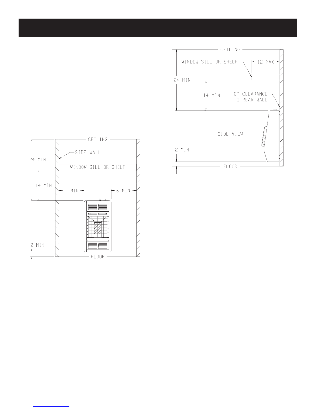
SR-10T CLEARANCES
When facing the front of the appliance the following minimum
clearances to combustible construction must be maintained.
Left side 6 inches (152mm). Right side 6 inches (152mm).
Do not install in alcove or closet.
Rear wall 0 inches (0mm). Ceiling 24 inches (610mm).
Minimum vertical clearance from a projection above the
appliance (shelves, window sills, etc.) 14 inches (356mm).
Maximum horizontal extension of projection above the appliance
12 inches (305mm).
Floor (top surface of carpeting, tile, etc.) 2 inches (51mm).
Provide adequate clearances around air openings.
Adequate accessibility clearances for purposes of servicing and
proper operation must be provided.
Figure 4 (SR-10T)
Figure 3 (SR-10T)
16941-8-0314Page 8
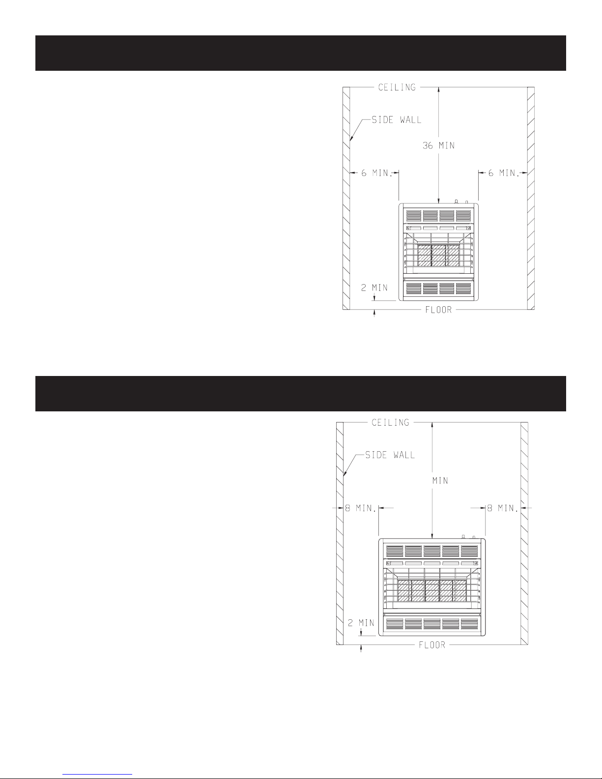
SR-18T CLEARANCES
When facing the front of the appliance the following minimum
clearances to combustible construction must be maintained.
Left side 6 inches (152mm). Right side 6 inches (152mm).
Do not install in alcove or closet.
Rear wall 0 inches (0mm). Ceiling 36 inches (914mm).
Minimum vertical clearance from a projection above the
appliance (shelves, window sills, etc.) 36 inches (914mm).
Floor (top surface of carpeting, tile, etc.) 2 inches (51mm).
Provide adequate clearances around air openings.
Adequate accessibility clearances for purposes of servicing and
proper operation must be provided.
(152mm)
(51mm)
(914mm)
(152mm)
Figure 5 (SR-18T)
SR-30T CLEARANCES
When facing the front of the appliance the following minimum
clearances to combustible construction must be maintained.
Left side 8 inches (203mm). Right side 8 inches (203mm).
Do not install in alcove or closet.
Rear wall 0 inches (0mm). Ceiling 36 inches (914mm).
Minimum vertical clearance from a projection above the
appliance (shelves, window sills, etc.) 36 inches (914mm).
Floor (top surface of carpeting, tile, etc.) 2 inches (51mm).
Provide adequate clearances around air openings.
Adequate accessibility clearances for purposes of servicing and
proper operation must be provided.
(203mm)
36” (914mm)
(203mm)
Figure 6 (SR-30T)
16941-8-0314 Page 9
(28 mm)
(300 mm)
(51)
(51)
(479 mm)
(102 mm)
(51 mm)
(559 mm)
(198 mm)
(28mm)
(613mm)
(511mm)
(51)
(51)
(559 mm)
2” (51 mm)
(479 mm)
(102 mm)
MIN
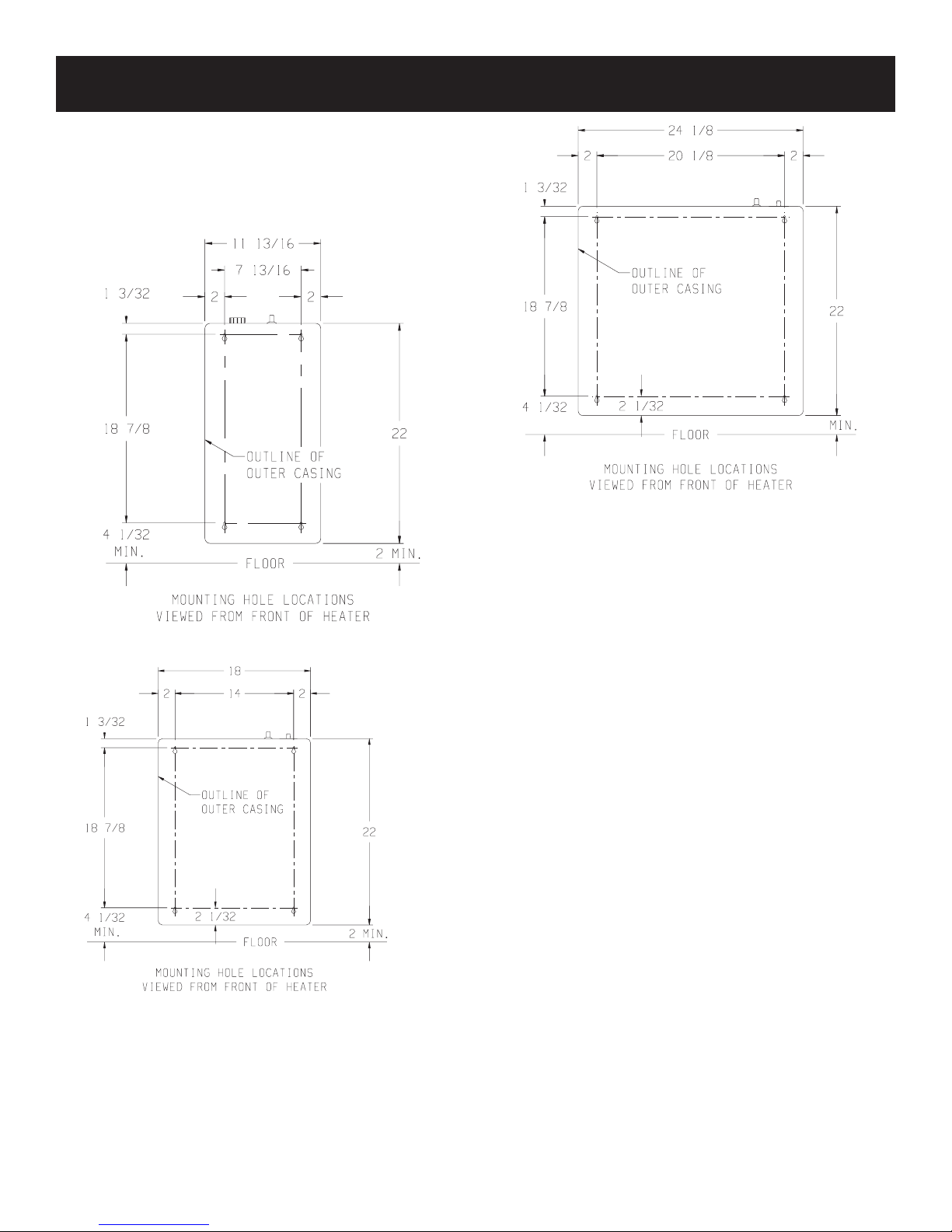
WALL MOUNT INSTALLATION
Refer to Figures 7, 8 and 9 for measurements in order to locate
(4) mounting holes on wall. Figures 7, 8 and 9 are the front views
of the heaters.
1. Remove lower louver from casing assembly (2 screws).
2. Remove reector from casing assembly (2 screws).
3. Remove upper louver from casing assembly (2 screws).
Figure 7 (SR-10T)
(457mm)
(356mm)
(28mm)
(479mm)
(102mm)
(52mm)
(559mm)
(51mm)
Figure 9 (SR-30T)
On Solid Wall
1. After locating mounting holes, attach (4) #10 x 1” (25mm) screws
provided into the wall. Do not completely tighten screwheads
to the wall, leave a 1/8” (3mm) gap between screwheads and
wall.
2. Mount heater onto the (4) screwheads and complete tightening
screwheads into the wall.
Attention! Use the following steps to properly align the upper
louver and the reector with the heat shield.
a. When replacing upper louver, be sure the bottom lip of upper
louver goes behind the heat shield.
b. When replacing reector, be sure the top lip of reector
goes in front of the heat shield.
3. Connect the gas line.
On Sheet Rock Wall
1. After locating mounting holes, drill (4) 5/16” (8mm) diameter
holes into the wall.
2. Insert (4) plastic expansion anchors provided into the holes.
3. Tighten (4) #10 x 1” (25mm) screws provided into the plastic
expansion anchors. Do not completely tighten screwheads to
the plastic expansion anchors, leave a 1/8” (3mm) gap between
screwheads and plastic expansion anchors.
Figure 8 (SR-18T)
16941-8-0314Page 10
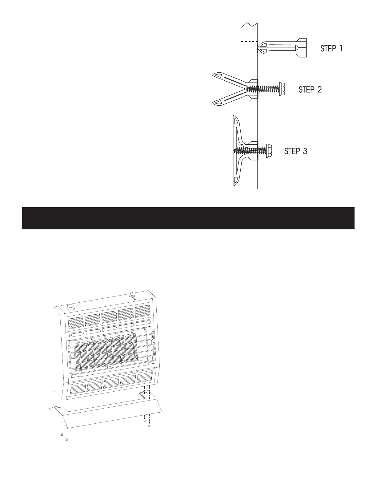
4. Mount heater onto the (4) screwheads and complete tightening
the screwheads to the plastic expansion anchors.
Attention! Use the following steps to properly align the upper
louver and the reector with the heat shield.
a. When replacing upper louver, be sure the bottom lip of upper
louver goes behind the heat shield.
b. When replacing reector, be sure the top lip of reector
goes in front of the heat shield.
5. Connect the gas line.
Figure 10
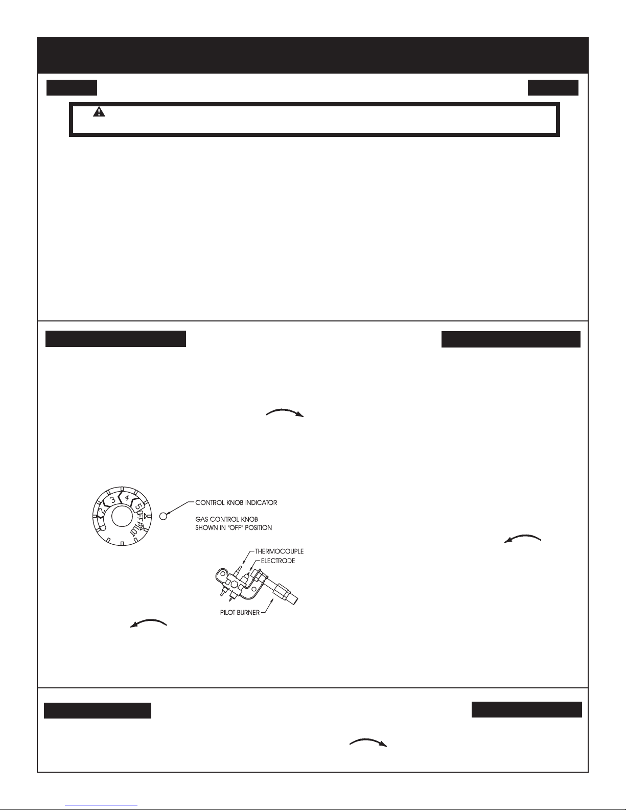
OPTIONAL FLOOR STAND INSTALLATION
1. Align clearance holes on oor stand with screw holes on bottom
of heater, as shown in Figure 11.
2. Attach oor stand to heater with (4) screws provided with oor
stand.
3. Connect the gas line.
*Floor stand can not be used in a bedroom installation. SR-10T
must be wall mounted in a bedroom installation.
Installation on Rugs and Tile
If this appliance is installed directly on carpeting, tile or other com-
bustible material, other than wood ooring, the appliance shall be
installed on a metal or wood panel extending the full width and
depth of the appliance.
Attention: Optional Floor Stand meets requirement.
The base referred to above does not mean the re-proof base as
used on wood stoves. The protection is for rugs that are extremely
thick and light colored tile.
SR-30T SHOWN
Figure 11
16941-8-0314 Page 11
LIGHTING INSTRUCTIONS
FOR YOUR SAFETY READ BEFORE LIGHTING
WARNING: If you do not follow these instructions exactly, a re or explosion may result causing
property damage, personal injury or loss of life.
A. This appliance has a pilot which must be lighted by hand.
When lighting the pilot, follow these instructions exactly.
B. BEFORE LIGHTING smell all around the appliance area for
gas. Be sure to smell next to the oor because some gas is
heavier than air and will settle on the oor.
WHAT TO DO IF YOU SMELL GAS
• Do not try to light any appliance.
• Do not touch any electrical switch;
do not use any phone in your building.
• Immediately call your gas supplier from a neighbor’s phone.
Follow the gas supplier’s instructions.
• If you cannot reach your gas supplier, call the re department.
LIGHTING INSTRUCTIONS
1. STOP! Read the safety information above.
2. Set thermostat (gas control knob) to lowest setting.
3. Turn off all electric power to the appliance (if applicable).
4. Push in gas control knob slightly and turn clockwise
to “OFF”. Do not force.
5. Wait ten (10) minutes to clear out any gas. Then smell for
gas, including near the oor. If you smell gas, STOP! Follow
“B” in the safety information above. If you don’t smell gas, go
to the next step.
6. Find pilot - the pilot is
attached at the bottom of
the burner assembly .
C. Use only your hand to push in or turn the gas control knob.
Never use tools. If the knob will not push in or turn by hand,
don’t try to repair it; call a qualied service technician. Force
or attempted repair may result in a re or explosion.
D. Do not use this appliance if any part has been under water.
Immediately call a qualied service technician to inspect the
appliance and to replace any part of the control system and
any gas control which has been under water.
back up. Pilot should remain lit. If it goes out, repeat steps 4
through 8.
• If knob does not pop up when released, stop and immediately call your service technician or gas supplier.
• If the pilot will not stay lit after several tries, turn the gas
control knob to “OFF” and call your service technician or
gas supplier.
9. Attention! Gas control has an INTERLOCK latching device.
When the pilot is initially lit and the safety magnet is energized
(pilot stays “ON”) the INTERLOCK latching device becomes
operative. If the gas control is turned to the “OFF” position or
gas ow to the appliance is shut off, the pilot cannot be relighted until the safety magnet is de-energized (approximately
60 seconds). There will be an audible “click” when the safety
magnet in the gas control is de-energized. Pilot can now be
relighted. Repeat steps 4 through 8.
10. Turn gas control knob counterclockwise to “HI”.
11. Turn on all electric power to appliance (if applicable).
12. Set thermostat (gas control knob) to desired setting from “HI”
to “LO”.
7. Turn gas control knob
counterclockwise to “PILOT.”
8. Push in gas control knob all the way and hold in. Repeatedly
push the piezo ignitor button until pilot is lit (or use a match to
light pilot). Continue to hold the control knob in for about one
(1) minute after the pilot is lit. Release knob and it will pop
TO TURN OFF GAS TO APPLIANCE
1. Set thermostat (gas control knob) to lowest setting.
2. Turn off all electric power to appliance if service is to be
performed (if applicable).
3. Push in gas control knob slightly and turn clockwise
to “OFF”. Do not force.
16941-8-0314Page 12
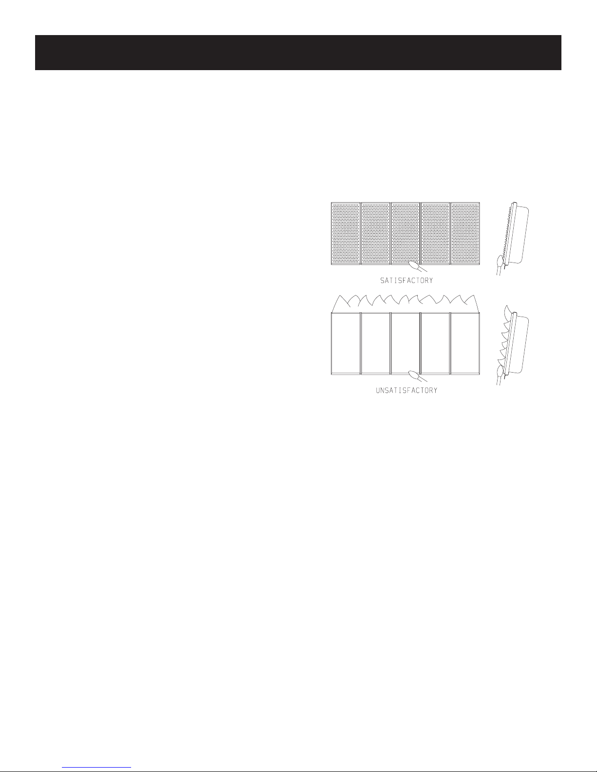
MAIN BURNER FLAME CHARACTERISTICS
SR-10T, SR-18T and SR-30T Main Burner Flame (Figure12)
The main burner ame will have a red-orange glow over the surface
of the ceramic plaques. A few small, hairline cracks may form over
the surface of the ceramic plaques or at the edges of the ceramic
plaques where they have been cemented into position on the burner
assembly frame. These small, hairline cracks will not affect the
operation or performance of the ceramic plaques. Only, when large
cracks develop, with blue ames escaping from the large cracks,
should you contact your QUALIFIED SERVICE PERSON.
A red-orange haze that is visible on the ceramic plaques is acceptable.
A blue ame that rolls out at the top of the ceramic plaques indicates
an accumulation of dust, lint or spider webs inside the casing assembly
and main burner assembly. Use the following procedure to inspect
the casing assembly and main burner assembly.
1. Turn OFF gas supply to the heater.
2. Turn OFF electric supply to the heater if optional blower is
installed in heater.
3. Remove lower louver from casing assembly ( 2 screws).
4. Remove reector from casing assembly (2 screws).
5. Inspect interior of casing assembly for accumulation of dust, lint
or spider webs. If necessary, clean interior of casing assembly
with a vacuum cleaner or apply air pressure. Do not damage any
components within casing assembly when you are cleaning.
6. Remove pilot bracket from main burner assembly (2 screws).
7. Pivot pilot bracket with attached pilot away from main burner
assembly (do not damage pilot tubing).
8. Inspect main burner orice(s) through the rectangular opening(s)
in the venturi (throat) of the main burner(s). Dust, lint and spider
webs can accumulate on top of the main burner orice(s). If
necessary, clean main burner orice(s) with a vacuum cleaner
or apply air pressure. To thoroughly clean the main burner
orice(s) proceed to Step 9.
9. Disconnect supply tubing from orice holder(s).
10. Remove orice holder from venturi of main burner assembly
(1 screw for each orice holder).
11. Remove main burner orice from orice holder.
12. Apply air pressure through main burner orice and orice holder
to remove dust, lint or spider webs.
13. Apply air pressure into ceramic plaque(s) to remove dust, lint
or spider webs.
14. As parts are being replaced in reverse order, check for gas
leaks at all gas connections before lower louver is replaced
onto casing assembly.
SR-30T SHOWN
Figure 12
16941-8-0314 Page 13
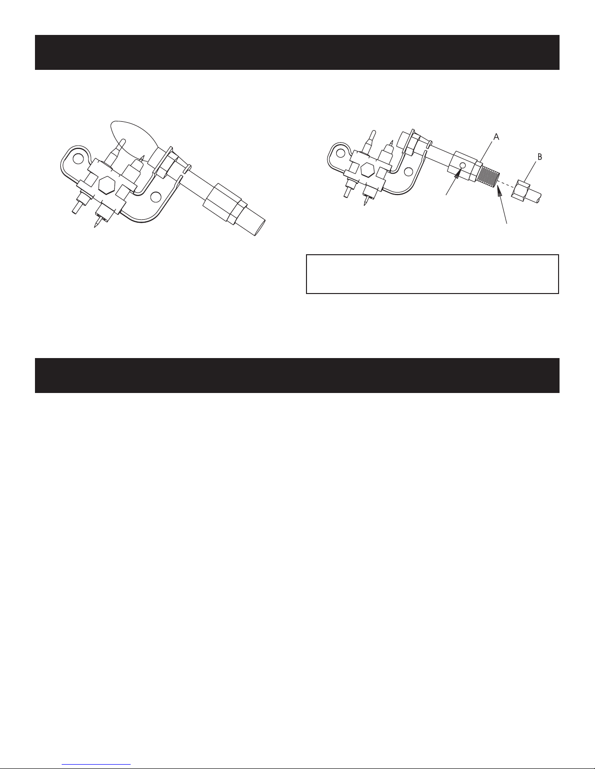
PILOT FLAME CHARACTERISTICS
The correct ame will be blue and will extend beyond the thermocouple. The ame will surround the thermocouple just below the
tip. A slight yellow ame may occur where the pilot ame and main
burner ame meet.
Figure 13
Oxygen Depletion Sensor Pilot (Figure 14)
When the pilot has a large yellow tip ame, clean the Oxygen
Depletion Sensor as follows:
1. Clean the ODS pilot by loosening nut B from the pilot tubing.
When this procedure is required, grasp nut A with an open end
wrench.
2. Blow air pressure through the holes indicated by the arrows.
This will blow our foreign materials such as dust, lint and spider
webs. Tighten nut B also by grasping nut A.
Figure 14
Never use needles, wires, or similar cylindrical objects to
clean the pilot to avoid damaging the calibrated ruby that
controls the gas ow.
THERMOSTAT OPERATION
To ignite main burner, turn gas control knob counterclockwise toward HI setting. To shut down main burner, turn gas control knob
clockwise toward LO setting.
The SR-10T has an input of 10,000 BTUH (2.9KW/H). The hydraulic
thermostat bulb is located at the casing assembly bottom. When the
hydraulic thermostat bulb senses the need for heat, the unit cycles
“ON” at a full input rate of 10,000 BTUH (2.9KW/H). The unit remains
at this full input rate until the hydraulic thermostat bulb is “satised.”
When the hydraulic thermostat bulb is “satised” the burner will shut
“OFF” with the pilot ame remaining “ON.”
The SR-18T has an input of 18,000 BTUH (5.3KW/H). The hydraulic
thermostat bulb is located at the casing assembly bottom. When the
hydraulic thermostat bulb senses the need for heat, the unit cycles
“ON” at a full input rate of 18,000 BTUH (5.3KW/H). The unit remains
at this full input rate until the hydraulic thermostat bulb is “satised.”
When the hydraulic thermostat bulb is “satised” the burner will shut
“OFF” with the pilot ame remaining “ON.”
NOTICE: The burner does not modulate between “ON” and the
pilot ame. When the SR-18T is “ON,” all three ceramic plaques
will “glow.” There will never be a time when only one or two ceramic
plaques are “glowing.”
The SR-30T has an input of 30,000 BTUH (8.8KW/H). The hydraulic
thermostat bulb is located at the casing assembly bottom. When the
hydraulic thermostat bulb senses the need for heat, the unit cycles
“ON” at a full input rate of 30,000 BTUH (8.8KW/H). The unit remains
at this full input rate until the hydraulic thermostat bulb is “satised.”
When the hydraulic thermostat bulb is “satised” the burner will shut
“OFF” with the pilot ame remaining “ON.”
NOTICE: The burner does not modulate between “ON” and the
pilot ame. When the SR-30T is “ON,” all ve ceramic plaques will
“glow.” There will never be a time when only one or three ceramic
plaques are “glowing.”
The LO and HI setting has temperature range of approximately 55°F
(12.78°C) to 90°F (32.22°C), respectively. This is the temperature at
the hydraulic thermostat bulb not the room temperature. The owner
is advised to determine the particular heat setting that is desired for
comfort, as heating requirements are different for every owner.
Attention: If the owner does not want the main burner to ignite and
turns the gas control knob to the LO setting, the main burner will
still ignite if the temperature at the hydraulic thermostat bulb drops
to 55°F (12.78°C).
If no heat is desired, turn the gas control knob to the PILOT position.
Main Burner Operation
Description of Gas Control Knob:
OFF position.
PILOT position.
LO/HI will allow the hydraulic thermostat bulb to cycle the heater
ON and OFF.
16941-8-0314Page 14

APPLIANCE MAINTENANCE
Removing Pilot/Thermocouple From Main Burner Assembly
Attention: The thermocouple CAN NOT be replaced as an individual
item. You must order a new pilot when replacing thermocouple.
1. Turn OFF gas supply to the heater.
2. Turn OFF electrical supply to the heater if optional blower is
installed in heater.
3. Remove lower louver from casing assembly (2 screws).
4. Remove reector from casing assembly (2 screws).
5. Disconnect pilot tubing from pilot (see Figure 14, Page 14).
Grasp nut A with a wrench when removing nut B with a second
wrench.
6. Remove pilot from pilot bracket (2 screws).
7. Remove thermocouple lead from gas valve.
8. As parts are being replaced in reverse order, check for gas
leaks at all gas connections before lower louver is replaced
onto casing assembly.
Removing Main Burner Orifice(s) From Main Burner
Assembly
1. Turn OFF gas supply to the heater.
2. Turn OFF electrical supply to the heater if optional blower is
installed in heater.
3. Remove lower louver from casing assembly (2 screws).
4. Remove reector from casing assembly (2 screws).
5. Remove pilot bracket from main burner assembly (2 screws).
6. Pivot pilot bracket with attached pilot away from main burner
assembly (do not damage pilot tubing).
7. Disconnect supply tubing from orice holder(s).
8. Remove orice holder from venturi of main burner assembly
(1 screw for each orice holder).
9. Remove main burner orice from orice holder. Attention: The
number stamped on the main burner orice is a millimeter
diameter.
10. As parts are being replaced in reverse order, check for gas
leaks at all gas connections before lower louver is replaced
onto casing assembly.
Removing Gas Valve From Casing Assembly
1. Turn OFF gas supply to the heater.
2. Turn OFF electrical supply to the heater if optional blower is
installed in heater.
3. Remove lower louver from casing assembly (2 screws).
4. Remove reector from casing assembly (2 screws).
5. Remove upper louver from casing assembly (2 screws).
6. If installed, remove optional blower assembly (4 screws).
7. Disconnect inlet supply tubing, outlet supply tubing, pilot supply
tubing and thermocouple lead from gas valve.
8. If heater is attached to wall, disconnect gas supply line from
inlet regulator.
9. Remove heater from wall.
10. Remove gas valve bracket from casing assembly (4 screws to
be removed are located on casing assembly back).
11. Remove hydraulic thermostat bulb from thermostat bulb clip
located at casing assembly bottom.
12. Remove gas valve from gas valve bracket.
13. As parts are being replaced in reverse order, check for gas
leaks at all gas connections before upper louver, reector and
lower louver are replaced onto casing assembly.
Removing Main Burner From Casing Assembly
1. Turn OFF gas supply to the heater.
2. Turn OFF electrical supply to the heater if optional blower is
installed in heater.
3. Remove lower louver from casing assembly (2 screws).
4. Remove reector from casing assembly (2 screws).
5. Disconnect supply tubing from orice holder(s).
6. Remove pilot bracket from main burner assembly (2 screws).
7. Remove main burner assembly from casing assembly (4
screws).
8. Remove orice shield from main burner assembly. Attach orice
shield to new main burner assembly.
9. As parts are being replaced in reverse order, check for gas
leaks at all gas connections before lower louver is replaced
onto casing assembly.
Piezo Pilot Ignitor Instructions
Depressing the ignitor button completely causes a spark to occur
at the pilot.
To light the pilot, it is important that the electrode be 1/8” (3mm)
from the pilot. The spark must occur at the point the pilot ame hits
the thermocouple.
On a new installation with air in the gas line, it is suggested that a
match be used. The match will light the pilot faster than the piezo
under this condition.
16941-8-0314 Page 15
 Loading...