

Empire Heating Systems PVS18N-3, PVS18P-3, PVS35N-3, PVS35P-3 Owner's Manual And Installation Instructions
OWNER’S MANUAL
AND INSTALLATION
INSTRUCTIONS
ULTRASAVER 90 PLUS
WALL FURNACE
MODELS
PVS18(N,P)-3
PVS35(N,P)-3
INSTALLER:
Leave this manual with the appliance.
CONSUMER:
Retain this manual for future reference.
WARNING
If the information in these instructions are
not followed exactly, a re or explosion may
result causing property damage, personal
injury or loss of life.
— Do not store or use gasoline or other
ammable vapors and liquids in the
vicinity of this or any other appliance.
— WHAT TO DO IF YOU SMELL GAS
• Do not try to light any appliance.
• Do not touch any electrical switch; do
not use any phone in your building.
• Leave the building immediately.
• Immediately call your gas supplier
from a neighbor’s phone. Follow the
gas supplier’s instructions.
• If you cannot reach your gas supplier,
call the re department.
—
Installation and service must be
performed by a qualied installer,
service agency or the gas supplier.
Attention: Check local codes for venting requirements.
WARNING
If not installed, operated and maintained
in accordance with the manufacturer’s
instructions, this product could expose you
to substances in fuel or from fuel combustion
which can cause death or serious illness.
Young children should be carefully supervised when
they are in the same room as the appliance.
If installed in a direct-vent application, this appliance
may be installed in an aftermarket, permanently
located, manufactured home or mobile home, where
not prohibited by state or local codes.
This appliance is only for use with the type of gas
indicated on the rating plate. This appliance is not
convertible for use with other gases, unless a certied
kit is used.
Carton Contents:
UltraSaver 90 Plus Wall Furnace (with shroud attached)
Instruction Envelope Containing:
Owner’s Manual and Installation Instructions
Shut-off Valve
2-1/2” Hose Clamp
Hardware Pack Containing:
(4) - #10 x 1-1/2” Hex Head Screws
4’ - 3/8 I.D. Condensate Drain Hose
Page 1
TABLE OF CONTENTS
SECTION PAGE
IMPORTANT SAFETY INFORMATION ........................................................................................ 3
SAFETY INFORMATION FOR USERS OF LP-GAS ...................................................................4
REQUIREMENTS FOR MASSACHUSETTS ...............................................................................5
GENERAL SAFETY INFORMATION ............................................................................................6
OWNER’S MANUAL AND OPERATION INSTRUCTIONS .................................................. 7 - 12
INSTALLATION INSTRUCTIONS ...................................................................................... 13 - 38
Introduction ..................................................................................................................... 14 - 20
FAQ - Installation Considerations ............................................................................................14
Accessories .............................................................................................................................15
Specications and Dimensions ...............................................................................................16
Clearances to Combustibles ...................................................................................................17
Wall Furnace Display ..............................................................................................................18
Wall Furnace Component Arrangement - Front ......................................................................19
Wall Furnace Component Arrangement - Rear .......................................................................20
Wall Furnace Installation ................................................................................................ 21 - 38
Mounting the Rear Shroud .............................................................................................. 21 - 22
Gas Supply ...................................................................................................................... 23 - 24
Vent Clearances ......................................................................................................................25
Venting Requirements .............................................................................................................26
Venting ............................................................................................................................. 27- 28
Vent Examples for Single Flue ........................................................................................ 29 - 30
Direct Vent Examples ...................................................................................................... 31 - 32
Lighting Instructions ................................................................................................................33
Wiring .............................................................................................................................. 34 - 35
Startup Checklist .....................................................................................................................36
Initial Startup and Adjustments ........................................................................................ 37 - 38
TROUBLESHOOTING ................................................................................................................39
MAINTENANCE & SERVICE ............................................................................................. 40 - 41
PARTS LIST ................................................................................................................................42
EXPLODED VIEW ......................................................................................................................43
MASTER PARTS DISTRIBUTOR LIST ......................................................................................44
HOW TO ORDER REPAIR PARTS ............................................................................................44
APPLIANCE SERVICE HITORY ........................................................................................ 45 - 46
WARRANTY ................................................................................................................................47
37873-0-0217Page 2
IMPORTANT SAFETY INFORMATION
THIS IS A HEATING APPLIANCE
Safety markings are frequently used in this manual to designate a degree or level of
seriousness and should not be ignored.
DANGER: Indicates a hazardous situation which, if not avoided, will result in death or
serious injury.
WARNING: Indicates a hazardous situation which, if not avoided, could result in death or
serious injury.
CAUTION: Indicates a hazardous situation which, if not avoided, could result in minor or
moderate injury.
Notice: Addresses practices not related to personal injury.
WARNING
This appliance must be installed and repaired by a qualied
service person. Installers who are not familiar with the
installation of the UltraSaver and have questions, should
contact Empire Comfort Systems, Inc. prior to installing the
appliance to avoid creating a hazardous operating condition.
• Due to high temperatures the appliance should be
located out of trafc and away from furniture and
draperies.
• Children and adults should be alerted to the hazards of
high surface temperatures and should stay away to avoid
burns or clothing ignition.
• Young children should be carefully supervised when they
are in the same room as the appliance.
• Clothing or other ammable material should not be
placed on or near the appliance.
• Any safety screen or guard removed for servicing an
appliance, must be replaced prior to operating the
appliance.
• Keep burner and control compartment clean.
• For manufactured home or mobile home or residential installation convertible for use with natural gas and
liqueed petroleum gases when provision is made for the
simple conversion from one gas to the other.
• Do not block warm air discharge. Do not allow anyone to
sleep directly in front of the wall furnace.
WARNING
The appliance should be inspected before use and at least
annually by a qualied service person. More frequent
cleaning may be required due to excessive lint from
carpeting, bedding materials, etc. It is imperative that control
compartments, burners and circulating air passageways of
the appliance be kept clean.
• DO NOT put anything around the appliance that will
obstruct the ow of combustion and ventilation air.
• DO keep the appliance area clear and free from combustible material, gasoline and other ammable vapors and
liquids.
• Do examine venting system periodically and replace
damaged parts.
• Do make a periodic visual check of burner. Clean and replace damaged parts.
• DO NOT use the appliance if any part has been under
water. Immediately call a qualied service technician
to inspect the appliance and to replace any part of the
control system and any gas control which has been
under water.
• DO NOT operate this appliance without the front panel
installed.
Note to the Installer
1. The installer must leave instruction manual with owner after
installation.
2. The installer must have the owner ll out and mail registration
card supplied with the wall furnace or register the wall furnace
online at www.empirezoneheat.com.
3. The installer should show the owner how to start and operate
wall furnace and thermostat.
4. The installer must locate wall furnace near a grounded wall
receptacle for 115VAC power and must provide gas supply
and vent the wall furnace properly for safe operation.
37873-0-0217 Page 3
SAFETY INFORMATION FOR USERS OF LP-GAS
Propane (LP-Gas) is a ammable gas which can cause res
and explosions. In its natural state, propane is odorless and
colorless. You may not know all the following safety precautions
which can protect both you and your family from an accident.
Read them carefully now, then review them point by point with
the members of your household. Someday when there may not
be a minute to lose, everyone’s safety will depend on knowing
exactly what to do. If, after reading the following information,
you feel you still need more information, please contact your
gas supplier.
LP-GAS WARNING ODOR
If a gas leak happens, you should be able to smell the gas
because of the odorant put in the LP-Gas.
That's your signal to go into immediate action!
• Do not operate electric switches, light matches, use your phone.
Do not do anything that could ignite the gas.
• Get everyone out of the building, vehicle, trailer, or area. Do
that IMMEDIATELY.
• Close all gas tank or cylinder supply valves.
• LP-Gas is heavier than air and may settle in low areas such as
basements. When you have reason to suspect a gas leak, keep
out of basements and other low areas. Stay out until reghters
declare them to be safe.
• Use your neighbor’s phone and call a trained LP-Gas service
person and the re department. Even though you may not
continue to smell gas, do not turn on the gas again. Do not
re-enter the building, vehicle, trailer, or area.
• Finally, let the service man and reghters check for escaped
gas. Have them air out the area before you return. Properly
trained LP-Gas service people should repair the leak, then
check and relight the gas appliance for you.
NO ODOR DETECTED - ODOR FADE
Some people cannot smell well. Some people cannot smell
the odor of the chemical put into the gas. You must nd out if
you can smell the odorant in propane. Smoking can decrease
your ability to smell. Being around an odor for a time can affect your
sensitivity or ability to detect that odor. Sometimes other odors in
the area mask the gas odor. People may not smell the gas odor or
their minds are on something else. Thinking about smelling a gas
odor can make it easier to smell.
The odorant in LP-gas is colorless, and it can fade under some
circumstances. For example, if there is an underground leak, the
movement of the gas through soil can lter the odorant. Odorants in
LP-Gas also are subject to oxidation. This fading can occur if there
is rust inside the storage tank or in iron gas pipes.
The odorant in escaped gas can adsorb or absorb onto or into
walls, masonry and other materials and fabrics in a room. That will
take some of the odorant out of the gas, reducing its odor intensity.
LP-Gas may stratify in a closed area, and the odor intensity could
vary at different levels. Since it is heavier than air, there may be
more odor at lower levels. Always be sensitive to the slightest gas
odor. If you detect any odor, treat it as a serious leak. Immediately
go into action as instructed earlier.
SOME POINTS TO REMEMBER
• Learn to recognize the odor of LP-gas. Your local LP-Gas
Dealer can give you a “Scratch and Sniff” pamphlet. Use it to
nd out what the propane odor smells like. If you suspect that
your LP-Gas has a weak or abnormal odor, call your LP-Gas
Dealer.
• If you are not qualied, do not light pilot lights, perform service,
or make adjustments to appliances on the LP-Gas system. If
you are qualied, consciously think about the odor of LP-Gas
prior to and while lighting pilot lights or performing service or
making adjustments.
• Sometimes a basement or a closed-up house has a musty
smell that can cover up the LP-Gas odor. Do not try to light
pilot lights, perform service, or make adjustments in an area
where the conditions are such that you may not detect the odor
if there has been a leak of LP-Gas.
• Odor fade, due to oxidation by rust or adsorption on walls of
new cylinders and tanks, is possible. Therefore, people should
be particularly alert and careful when new tanks or cylinders
are placed in service. Odor fade can occur in new tanks, or
reinstalled old tanks, if they are lled and allowed to set too
long before relling. Cylinders and tanks which have been out
of service for a time may develop internal rust which will cause
odor fade. If such conditions are suspected to exist, a periodic
sniff test of the gas is advisable. If you have any question
about the gas odor, call your LP-gas dealer. A periodic
sniff test of the LP-gas is a good safety measure under
any condition.
• If, at any time, you do not smell the LP-Gas odorant and you
think you should, assume you have a leak. Then take the same
immediate action recommended above for the occasion when
you do detect the odorized LP-Gas.
• If you experience a complete “gas out,” (the container is under
no vapor pressure), turn the tank valve off immediately. If the
container valve is left on, the container may draw in some air
through openings such as pilot light orices. If this occurs, some
new internal rusting could occur. If the valve is left open, then
treat the container as a new tank. Always be sure your container is under vapor pressure by turning it off at the container
before it goes completely empty or having it relled before it is
completely empty.
37873-0-0217Page 4
REQUIREMENTS FOR MASSACHUSETTS
For all side wall horizontally vented gas fueled equipment installed
in every dwelling, building or structure used in whole or in part for
residential purposes, including those owned or operated by the
Commonwealth and where the side wall exhaust vent termination
is less than seven feet above nished grade in the area of the
venting, including but not limited to decks and porches, the
following requirements shall be satised:
1. INSTALLATION OF CARBON MONOXIDE DETECTORS.
At the time of installation of the side wall horizontal vented
gas fueled equipment, the installing plumber or gastter shall
observe that a hard wired carbon monoxide detector with an
alarm and battery back-up is installed on the oor level where
the gas equipment is to be installed. In addition, the installing
plumber or gastter shall observe that a battery operated
or hard wired carbon monoxide detector with an alarm is
installed on each additional level of the dwelling, building or
structure served by the side wall horizontal vented gas fueled
equipment. It shall be the responsibility of the property owner
to secure the services of qualied licensed professionals for
the installation of hard wired carbon monoxide detectors
a. In the event that the side wall horizontally vented gas
fueled equipment is installed in a crawl space or an attic,
the hard wired carbon monoxide detector with alarm and
battery back-up may be installed on the next adjacent
oor level.
b. In the event that the requirements of this subdivision
can not be met at the time of completion of installation,
the owner shall have a period of thirty days to comply
with the above requirements; provided, however, that
during said thirty day period, a battery operated carbon
monoxide detector with an alarm shall be installed.
2. APPROVED CARBON MONOXIDE DETECTORS. Each
carbon monoxide detector as required in accordance with the
above provisions shall comply with NFPA 720 and be ANSI/
UL 2034 listed and IAS certied.
3. SIGNAGE. A metal or plastic identication plate shall be
permanently mounted to the exterior of the building at a
minimum height of eight feet above grade directly in line
with the exhaust vent terminal for the horizontally vented
gas fueled heating appliance or equipment. The sign shall
read, in print size no less than one-half (1/2) inch in size,
“GAS VENT DIRECTLY BELOW. KEEP CLEAR OF ALL
OBSTRUCTIONS”.
4. INSPECTION. The state or local gas inspector of the side
wall horizontally vented gas fueled equipment shall not
approve the installation unless, upon inspection, the inspector
observes carbon monoxide detectors and signage installed
in accordance with the provisions of 248 CMR 5.08(2)(a) 1
through 4.
(b) EXEMPTIONS: The following equipment is exempt from
248 CMR 5.08(2)(a)1 through 4:
1. The equipment listed in Chapter 10 entitled
“Equipment Not Required To Be Vented” in the most
current edition of NFPA 54 as adopted by the Board;
and
2. Product Approved side wall horizontally vented gas
fueled equipment installed in a room or structure
separate from the dwelling, building or structure
used in whole or in part for residential purposes.
(d) MANUFACTURER REQUIREMENTS - GAS
EQUIPMENT VENTING SYSTEM NOT PROVIDED.
When the manufacturer of a Product Approved side
wall horizontally vented gas fueled equipment does not
provide the parts for venting the ue gases, but identies
“special venting systems”, the following requirements
shall be satised by the manufacturer:
1. The referenced “special venting system” instructions
shall be included with the appliance or equipment
installation instructions; and
2. The “special venting systems” shall be Product
Approved by the Board, and the instructions for
that system shall include a parts list and detailed
installation instruction.
(e) A copy of all installation instructions for all Product
Approved side wall horizontally vented gas fueled
equipment, all venting instructions, all parts lists for
venting instructions, and/or all venting design instructions
shall remain with the appliance or equipment at the
completion of the installation.
37873-0-0217 Page 5
Commonwealth of Massachusetts: The installation must be
made by a licensed plumber or gas tter in the Commonwealth
of Massachusetts.
GENERAL SAFETY INFORMATION
WARNING
The safety information listed below must be followed
during the installation, service, and operation of this
product. Failure to following the safety recommendations
could result in possible damage to the equipment, serious
personal injury, or death.
General Information
This series is designed certied in accordance with American National Standard/CSA Standard Z21.86 and CSA 2.32 as a power
vent wall furnace to be installed according to these instructions.
Any alteration of the original design, installed other than as
shown in these instructions will be the responsibility of the
person and company making the changes, and will void the
warranty. This product may not be used with any type of gas
other than what is shown on the rating plate unless converted
using an Empire approved conversion kit.
Installation
Installation and replacement of gas piping, gas utilization equipment or accessories, and the repair and servicing of this equip-
ment must be performed by a qualied agency. The term “qualied
agency” means any individual, rm, corporation or company which
either in person or through a representative is engaged in and is
responsible for (a) the installation or replacement of gas piping or
(b) the connection, installation, repair or servicing of equipment,
who is experienced in such work, familiar with all precautions required and has complied with all the requirements of the authority
having jurisdiction.
• This installation must conform with local codes, or in the
absence of local codes, the National Fuel Gas Code,
NFPA 54/ANSI Z223.1.
• This appliance, when installed, must be electrically grounded
in accordance with local codes or. In the absence of local
codes, with the National Electrical Code, ANSI/NFPA 70.
• Provide adequate clearances around the wall furnace for servicing and ensure there are no obstructions to the combustion
air intake situated at the back of the wall furnace. Refer to
Pages 16 and 17.
•
This wall furnace is equipped with a three-prong [grounding] plug for your protection against shock hazard and
should be plugged directly into a properly grounded
three-prong receptacle. Do not cut or remove the grounding prong from this plug. For an ungrounded receptacle,
purchase an adapter with two prongs and a wire for grounding.
• This installation must conform with local codes, or in the
absence of local codes, in Canada use Canadian Electrical
Code CSA C22.1 and in the United States use the National
Fuel Gas Code NFPA 54/ANSI Z223.1.
• This appliance, when installed, must be electrically grounded in accordance with local codes or. In the absence of local codes, in Canada with the Canadian Electrical Code CSA
C22.1 and in the United States with the National Electrical
Code ANSI/NFPA 70.
A manufactured home (USA only) or mobile home OEM installation must conform with the Manufactured Home Construction and
Safety Standard, Title 24 CFR, Part 3280, or when such a standard is not applicable, the Standard for Manufactured Home Installations, ANSI/NCSBCS Z225.1, or Standard for Gas Equipped
Recreational Vehicles and Mobile Housing, CSA Z240.0.
Installation in Residential Garages
Gas utilization equipment in residential garages shall be installed so
that all burners and burner ignition devices are located not less than
18 inches (457 mm) above the oor. The equipment shall be located, or protected, so it is not subject to physical damage by vehicles.
Operation of Wall furnace During Construction
The wall furnace shall not be used during construction.
WARNING
Any change to this wall furnace or its control can be dangerous.
WARNING
This is a heating appliance and any panel, door or guard
removed for servicing the appliance must be replaced prior
to operating the appliance.
NOTICE: During initial ring of this wall furnace, residual oil from
the heat exchanger may bake off and smoke may occur.
Provide adequate ventilation to the area where the
wall furnace is installed to prevent triggering of smoke
alarms. Refer to page 36 for more detail.
Additional code information listed below is for reference purposes only and does not necessarily have jurisdiction over
local or state codes. Always consult with local authorities before installing any gas appliance.
Attention: This appliance may be installed in the U.S. or in
Canada.
Combustion and Ventilation Air
U.S.: National Fuel Gas Code NFPA 54/ANSI Z223.1(NFGC),
Air for Combustion and Ventilation.
CANADA: National Standard of Canada for Natural Gas and
Propane Installation Codes (NSCNGPIC)
CAN/CGA-B149.1 and .2, Part 7, Venting Systems and Air
Supply for Appliances
Electrical Connections
U.S.: National Electrical Code (NEC) ANSI/NFPA 70
CANADA: Canadian Electrical Code CSA C22.1
Gas Piping and Gas Pipe Pressure Testing
U.S.: NFGC and National Plumbing Codes
CANADA: NSCNGPIC Part 5
General Installations
U.S.: Current edition of the NFGC and NFPA 90B. For copies contact the National Fire Protection Association Inc., Batterymarch
Park, Quincy, MA 02269 or American Gas Association, 400 N.
Capitol, N.W., Washington DC 20001 or www.NFPA.org.
CANADA: NSCNGPIC. For a copy, contact Standard Sales, CSA
International, 178 Rexdale Blvd., Etobicoke (Toronto), Ontario,
M9W 1R3 Canada
Safety
U.S.: NFGC NFPA 5/ANSI Z223.1
CANADA: (NSCNGPIC) CAN/GCA-B149.1 and .2 National
Standard of Canada
37873-0-0217Page 6
OWNER’S MANUAL
AND
OPERATION INSTRUCTIONS
37873-0-0217 Page 7
www.empirezoneheat.com
OWNER’S MANUAL
Before You Start
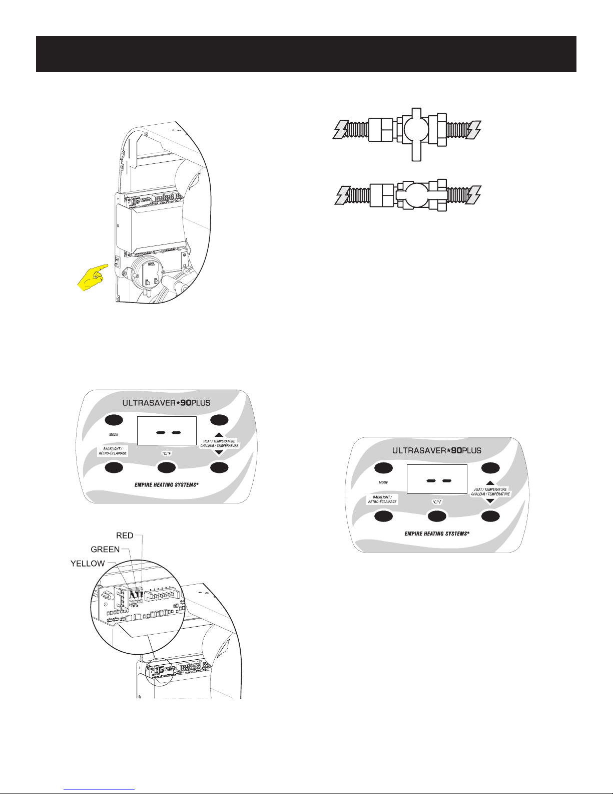
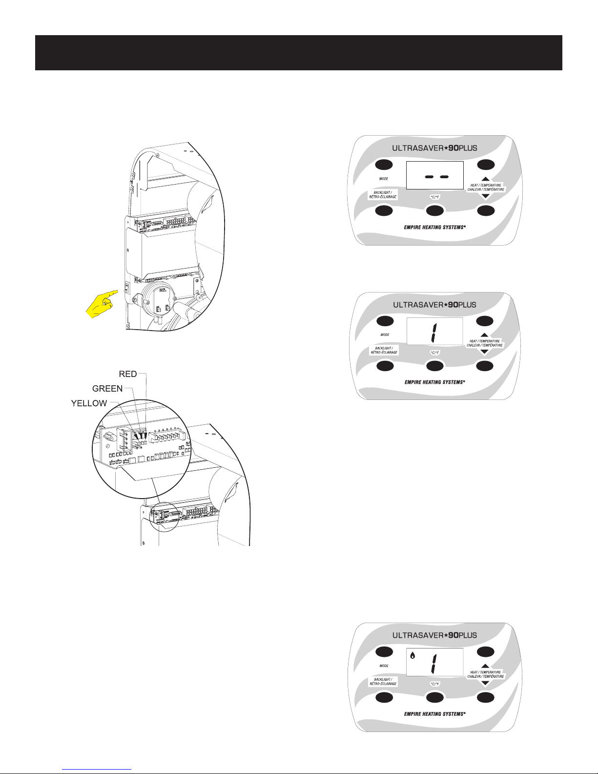
1. Verify there is electrical power to the wall furnace.
Verify the Main Power Switch is turned on. See Figure 1.
Figure 1
If electrical power is present, the red and green control board
LED’s will begin to ash alternately. See Figure 3. Each light will
ash four times then the wall furnace will enter standby mode.
While in remote mode, the green LED will ash slowly and the
display panel will show a double dash “ - - “. See Figure 2.
2. Verify the main gas supply to the unit is on.
The shutoff valve should be in the “OPEN” position. See Figure 4.
CLOSED
OPEN
Figure 4
Starting the Wall Furnace
The wall furnace has three modes for controlling operation:
Remote, Manual and Local. When in Remote mode, the wall
furnace can be operated by an external Millivolt thermostat,
remote control, or on/off wall switch. When in Manual mode, the
wall furnace can be turned on and off and the heat level adjusted
manually from the display panel. When operating in Local mode,
the owner sets a desired room temperature on the display panel
and the wall furnace will automatically turn on and off and adjust
the heat level to achieve the set temperature.
Wall Furnace Operation - Remote Mode (External Millivolt
Thermostat or Remote)
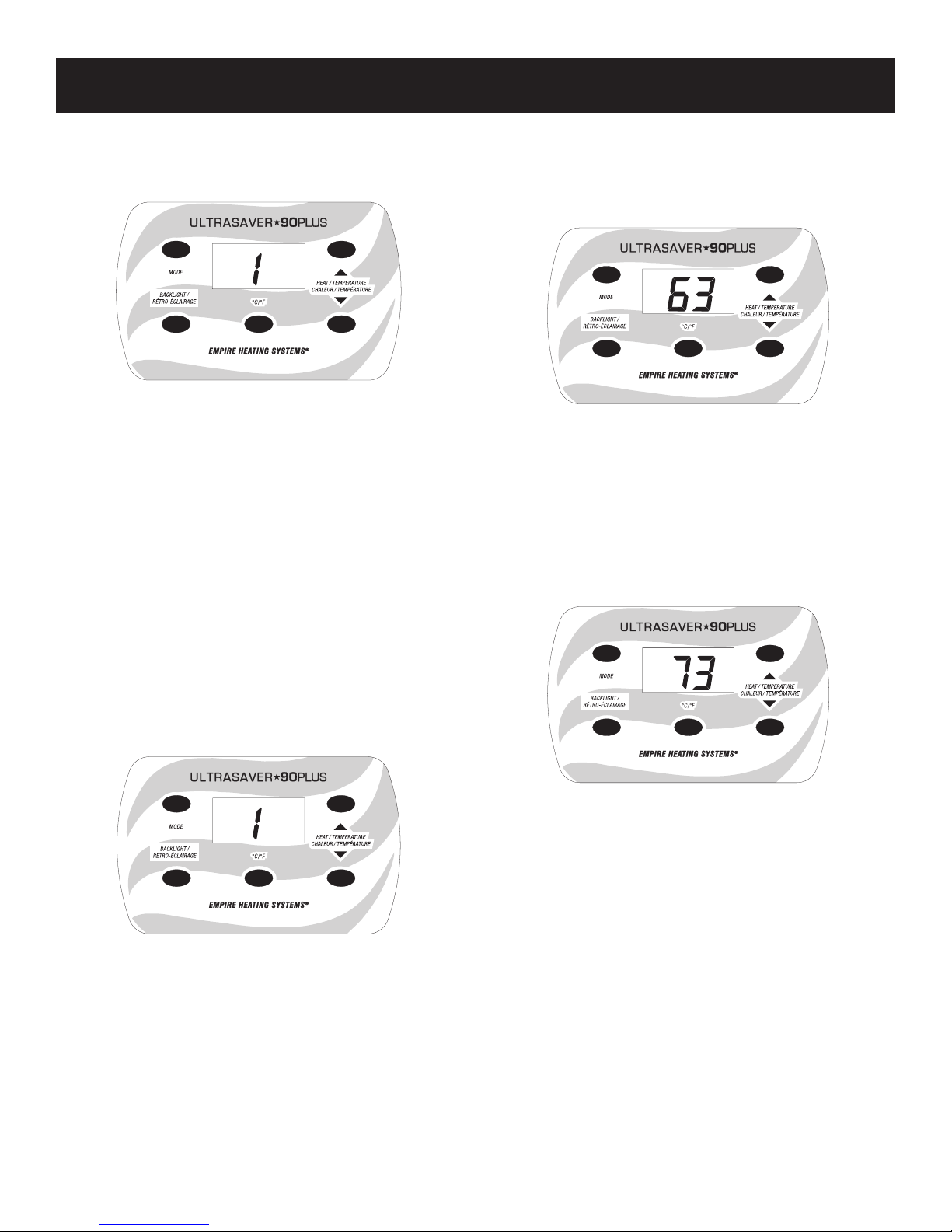
1. To initiate the wall furnace Remote mode, press the “Mode
Select” button on the wall furnace display panel once from
OFF mode to display a double dash “ - - “. See Figure 5.
Figure 2
Figure 3
If the control board LED’s do not activate, verify the wall furnace
is plugged in and the breaker is on. If the wall furnace is still not
activated, contact a qualied service technician.
Figure 5
37873-0-0217Page 8
OWNER’S MANUAL
2. When the external control is activated, the wall furnace display panel will illuminate and show the heat level along with
the remote signal symbol. The wall furnace will begin the
start up sequence automatically. See Figure 6.
Figure 6
Notice: When a Millivolt thermostat or on/off switch is used, the
wall furnace will only operate on high (Level 5).
Notice: When operating in Remote mode, a button sequence
may be used to lock the display panel. See page 12.
3. If a Millivolt thermostat or thermostatic remote is used, set to
the desired room temperature. The wall furnace will turn on
and off automatically in response to the thermostat.
Wall Furnace Operation - Manual Mode
Notice: When operating the wall furnace in Manual mode from
the display panel, only basic operations are available: On, off and
heat level adjustment.
1. To operate the wall furnace in Manual mode, press the “Mode
Select” button on the display panel twice from off mode until
a number appears in the Heat Level location on the display
panel. See Figure 7. The wall furnace will begin the start up
sequence.
Wall Furnace Operation - Local Mode (Internal Thermostat)
1. To operated the wall furnace in Local (thermostatic) mode,
press the Mode Select button on the wall furnace display
panel three times from the off mode. The display panel will
show the current room temperature. See Figure 8.
Figure 8
Notice: The temperature sensing probe is built into the left rear
of the wall furnace. A kit to relocate the probe is available. See
page 15.
2. Use the up and down adjustment buttons on the display
panel to set the desired room temperature.
The display will illuminate and the word “SET” will appear
in the top right corner of the display. See Figure 9. After the
temperature is set, the display panel will darken and return
to displaying the room temperature.
Figure 7
2. Use the UP and DOWN adjustment buttons on the right of the
display panel to set the desired level. The display will illuminate and the word “SET” will appear in the top right corner of
the display. After the level is set, the display panel will darken
and the heat level will be displayed.
37873-0-0217 Page 9
Figure 9
3. When the room temperature drops to 3°F below the set temperature, the wall furnace will begin the start up sequence.
4. The wall furnace will automatically adjust the starting level to
meet the heat demand.
Notice: The greater the difference between the room and de-
sired temperatures the higher the starting level.
As the room temperature nears the desired temperature the
level will decrease.
5. The wall furnace will turn off if the room temperature rises
slightly above the set temperature when operating at level 1.
Notice: The wall furnace will adjust the heat level in order to
reach a point of equilibrium between the room and desired temperatures. This may cause the wall furnace to operate for long
periods of time at low levels.
When the backlight button is pushed, the display will cycle between the level, set temperature and room temperature.
Notice: While the wall furnace is operating in Local mode, the
display will only show the room temperature unless the backlight
button is pushed.
OWNER’S MANUAL
Wall Furnace Operations Sequence
1. When the main power switch is turned on, the red and green
control board LED’s will begin to ash alternately. If using the
FRBTPL Remote accessory (page 15) the remote receiver
will search for the remote transmitter’s signal. See Figures
10 and 11.
Figure 10
Each light will pulse four times then the wall furnace will
enter Remote mode. While in Remote mode, the green LED
will ash slowly and the display panel will shown a double
dash “- -”. See Figure 12.
Figure 12
2. When a call for heat is received, the wall furnace display
panel will illuminate and show the level. See Figure 13.
Figure 11
Figure 13
3. Adjust level with the up and down adjustment buttons in Manual Mode. If operating in Local mode, the heat level will adjust
automatically.
4. The red and green control panel LED lights will begin to ash
alternately while the wall furnace performs a safety test. After
approximately 45 seconds the test will complete and the wall
furnace will prepare to ignite.
5. After the safety test is complete, the ignitor will glow red and
the burner will light within approximately 30 seconds.
Notice: If the burner fails to light, the wall furnace will retry the
ignition sequence three times then enter lock-out mode if it fails
to light. See page 39 for the fault codes and their meanings.
6. After the burner lights, the ame icon on the display panel will
appear and the wall furnace will automatically adjust to the
heat level shown on the display. The wall furnace will always
ignite on Level 5 (High) prior to adjusting to the heat level
shown on the display panel. See Figure 14.
Figure 14
37873-0-0217Page 10
OWNER’S MANUAL
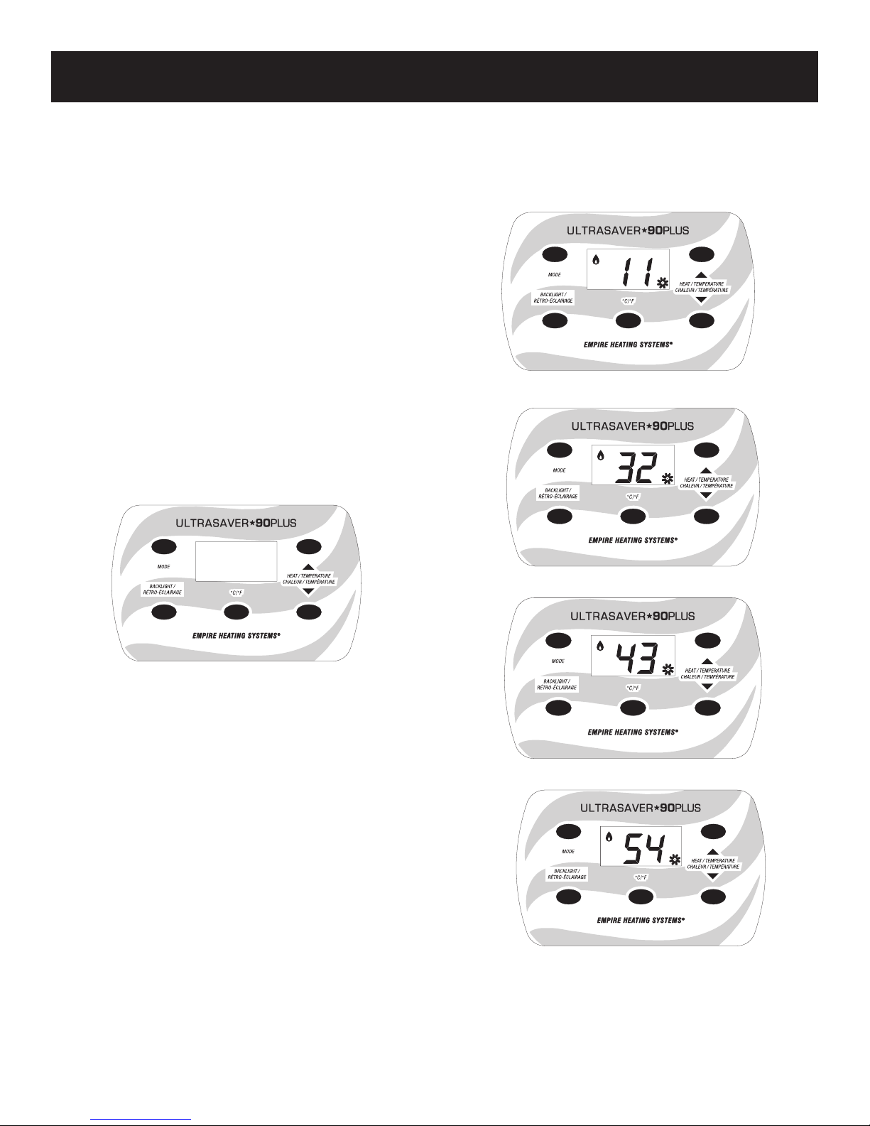
7. The blower will activate after 45 to 70 seconds depending on
heat level. The blower will automatically adjust its speed to
match the heat level. The blower speed will be indicated on
the display panel. See Figures 16 to 19.
8. The heat level can be adjusted either up or down at any
point during the wall furnace’s operation in Manual Mode.
If using the Local mode, the wall furnace adjusts the level
automatically.
Notice: When changing from a low heat level to a higher heat
level, the wall furnace will automatically increase to Level 5
(High) prior to proceeding to the desired heat level. This is to
ensure consistent operation.
9. When the wall furnace is shut down, the inducer will operate
at full power for approximately 10 seconds after the burner is
extinguished. This is to clear any ue products from the wall
furnace’s combustion chamber. The circulating air blower will
continue to operate from 100 to 160 seconds to ensure the
wall furnace cools sufciently.
Turning the Wall Furnace Off - Display Panel
To turn the wall furnace off from the display panel, press the “Mode
Select” button on the wall furnace display panel until the panel
turns off.
Circulating Air Blower Operation
The circulating air blower is operated by a built in timer. The blower
will activate after approximately 45 to 70 seconds depending on
heat level. The blower will automatically adjust its speed to match
the heat level. The blower icon and speed are indicated on the
display panel. See Figures 16 to 19.
Figure 16 - Heat Levels 1 and 2, Blower Speed 1
Figure 15
The burner will instantly go off, but the circulating air blower will
continue to operate from 100 to 160 seconds to ensure the wall
furnace cools off.
Power Interruption
The wall furnace requires a 115VAC power source to operate. See
Specications on page 16.
When power is restored to the wall furnace after a power interruption, the wall furance will automatically reactivate in “Remote” (--)
mode and all operation settings will have reset to the factory defaults. If the wall furnace is normally operated using Manual mode
or with the built-in thermostat, the operation settings will need to
be manually reset to the desired mode and settings to resume
operation.
Installing an optional Millivolt thermostat allows the wall furnace to
automatically resume operation once power is restored.
Figure 17 - Heat Level 3, Blower Speed 2
Figure 18 - Heat Level 4, Blower Speed 3
Figure 19 - Heat Level 5, Blower Speed 4
After the wall furnace is turned off, the blower will continue to operate for 100 to 160 seconds to ensure the wall furnace cools suf-
ciently.
Notice: When the wall furnace is turned off, the blower speed will
be displayed while it is running.
37873-0-0217 Page 11
OWNER’S MANUAL
Humidier Operation
With the optional humidication tray kit (page 15), as the wall furnace operates condensate is collected and transferred to a pan in
the bottom of the wall furnace. When the condensate reaches a
certain level, a heating element evaporates the water into the air
stream.
While the condensate is being evaporated, the “AUX” symbol will
be displayed. See Figure 20.
Notice: The humidier may not operate with every cycle.
AUX
Figure 20
Troubleshooting
This wall furnace’s controls include a troubleshooting feature
which will display a code on the display panel should an error occur. See page 39 for a list of troubleshooting codes. Some codes
will require the system to be reset.
To reset the wall furnace, press the mode selection button on the
display panel repeatedly until the wall furnace cycles through the
“OFF” setting once. If the error has been cleared, the wall furnace
will operate normally. If the error is still present, consult a qualied
service technician.
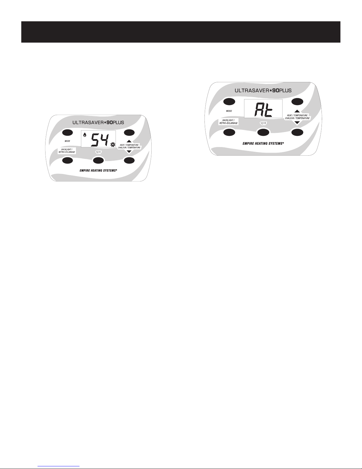
Remote Mode - Anti-tamper
To lock the display panel when operating the wall furnace in
remote mode, press and hold the Mode, Up adjust and Down
adjust buttons for ten seconds. The display panel will display “At”.
See Figure 21.
Figure 21
After the display panel darkens it will show the level and blower
speed as normal during operation. When the wall furnace is in an
OFF cycle, the display panel will show “At”.
To deactivate the Anti-tamper mode, press and hold the Mode,
Up adjustment and Down adjustment buttons for ten seconds.
The display will return to the double dash “- -”.
37873-0-0217Page 12

INSTALLATION
INSTRUCTIONS
37873-0-0217 Page 13
www.empirezoneheat.com

INTRODUCTION
FAQ - INSTALLATION CONSIDERATIONS
What tools are needed for installation?
Pipe Wrench
Adjustable Wrench
Drill
Tape Measure
10” x 5/16” Nut Driver
Thread Sealant
Level
2-1/2” Diameter Hole Saw for 2” pipe
2” Diameter Hole Saw for 1-1/2” pipe
1” Diameter Hole Saw
Non-corrosive Leak Check Solution
Where will the wall furnace be installed?
• On the Floor - Wall Furnace comes equipped from
factory for this option. See Page 21.
• Wall Mounted - Wall mount shroud needed. See
Page 15 for kit number.
• Mount wall furnace at a height so that the controls can still be observed.
• Interior Wall - Maximum vent length is 50 feet.
• Exterior Wall
• Locate Electrical Supply - Extension cords may
NOT be used.
• Wall Furnace Dimensions page 16.
• Clearances to Combustibles page 17.
What kind of venting application will be used?
• Single Flue - Wall Furnace comes equipped from
factory for this option. A 2” or 1-1/2” pipe may be
used. If a 1-1/2” pipe is used, it must be enlarged to
a 2” pipe prior to exiting the wall into the shroud.
• Direct Vent - An “Air Pipe Kit” is required and is
available for order. See page 15.
How will the condensate be disposed?
• To a drain - Wall Furnace comes equipped from the
factory to drain up to 3 feet away from the appliance.
• An Extension Kit and External Condensate Pump
kit may also be used. See page 15 for kit numbers.
• Humidication - Optional Heated Humidication Tray
Kit available for order. See page 15 for kit number.
• Winterization information on page 41.
How will the wall furnace be operated?
• Remote - external Millivolt thermostat, wall switch or
remote control. See page 15 for kits available from
Empire Comfort Systems.
• Manual - use the display panel to control the heating
level and turn the wall furnace on and off.
• Local (Internal Thermostatic) - Factory installed
temperature probe on the wall furnace with a builtin thermostatic function to control the wall furnace’s
operation.
• If it is desired to use the temperature sensed in
another part of the room, a wired temperature
probe accessory kit is available. See page 15 for
kit numbers.
• See Operation Instructions pages 7 to 12.
• Notice: Following a power outage, this wall furnace
will not automatically resume operation when operated manually or with the internal thermostat. Once
power is restored, the wall furnace will automatically
power on in “Remote Mode” (--), and the original operation settings will need to be re-entered. Installing
an optional Millivolt thermostat control allows the wall
furnace to automatically resume operation under that
thermostat’s control once power is restored. Ask your
dealer for details.
How will the venting be run?
• Straight out the back - Wall Furnace comes
equipped from factory for this option. Standard Rear
Shroud supplied. See page 27.
• In Front of the wall - Deep Shroud needed. Venting
option may NOT be done in Wall Mount installations.
See page 15 for kit number.
• Venting Guidelines pages 25 to 32.
• Maximum vent length is 50 feet.
• Notice: Clean all debris from the inside of the ue
pipe prior to applying the glue and nal assembly
of the pipe. Since the condensate is designed to
ow back to the appliance this debris will be carried
to the condensate trap resulting in a clog. An “A2”
error will appear on the display panel if this happens.
The clog, and the work required to x it, can be easily prevented by pulling a wet cloth through the pipe
prior to applying the glue and nal assembly.
37873-0-0217Page 14
INTRODUCTION
ACCESSORIES
ACCESSORIES
VENTING
Part Number Description Typical Uses
PVSA1 Air Pipe Kit
PVSDV35A DV35 Vent Transition Cap Replaces DV35 Vent cap with a transition to PVC pipe for a 2” single ue
Part Number Description Typical Uses
PVSDS1 Deep Rear Shroud Allows venting to be run in front of the wall in on the oor installations
PVSWS1 Wall Mount Shroud Allows installation of wall furnace off of the oor
Part Number Description Typical Uses
PVSHT2 Heated Humidication Tray Evaporates condensate as humidity back into the room
PVSEP2 External Condensate Pump Pumps condensate away from wall furnace instead of gravity drain
PVSCT10 Condensate Hose Extension 10 ft condensate drain extension
Part Number Description Features
PVSRT1 Temperature Sensor Relocation Kit Room Temperature Sensor Extension
Notice: Following a power outage, this wall furnace will not automatically resume operation when operated manually or with
the internal thermostat. Once power is restored, the wall furnace will automatically power on in “Remote Mode” (--), and the
original operation settings will need to be re-entered. Installing an optional Millivolt thermostat control allows the wall furnace
to automatically resume operation under that thermostat’s control once power is restored. Ask your dealer for details.
Converts wall furnace from single ue to direct-vent (Comes standard with heater)
SHROUDS
CONDENSATE KITS
CONTROLS
IMPORTANT
All correspondence regarding repair and service should
refer to complete Model Number, Serial Number and type
of gas.
Removing the Front Panel
It may become necessary to remove the front panel of the
appliance to remove dropped or fallen objects.
Remove the front panel by lifting up then pulling out. Replace the panel by reversing this step.
WARNING
FOR YOUR SAFETY, TURN OFF POWER TO APPLIANCE.
WARNING
Do not operate this appliance without the front panel.
37873-0-0217 Page 15
INTRODUCTION
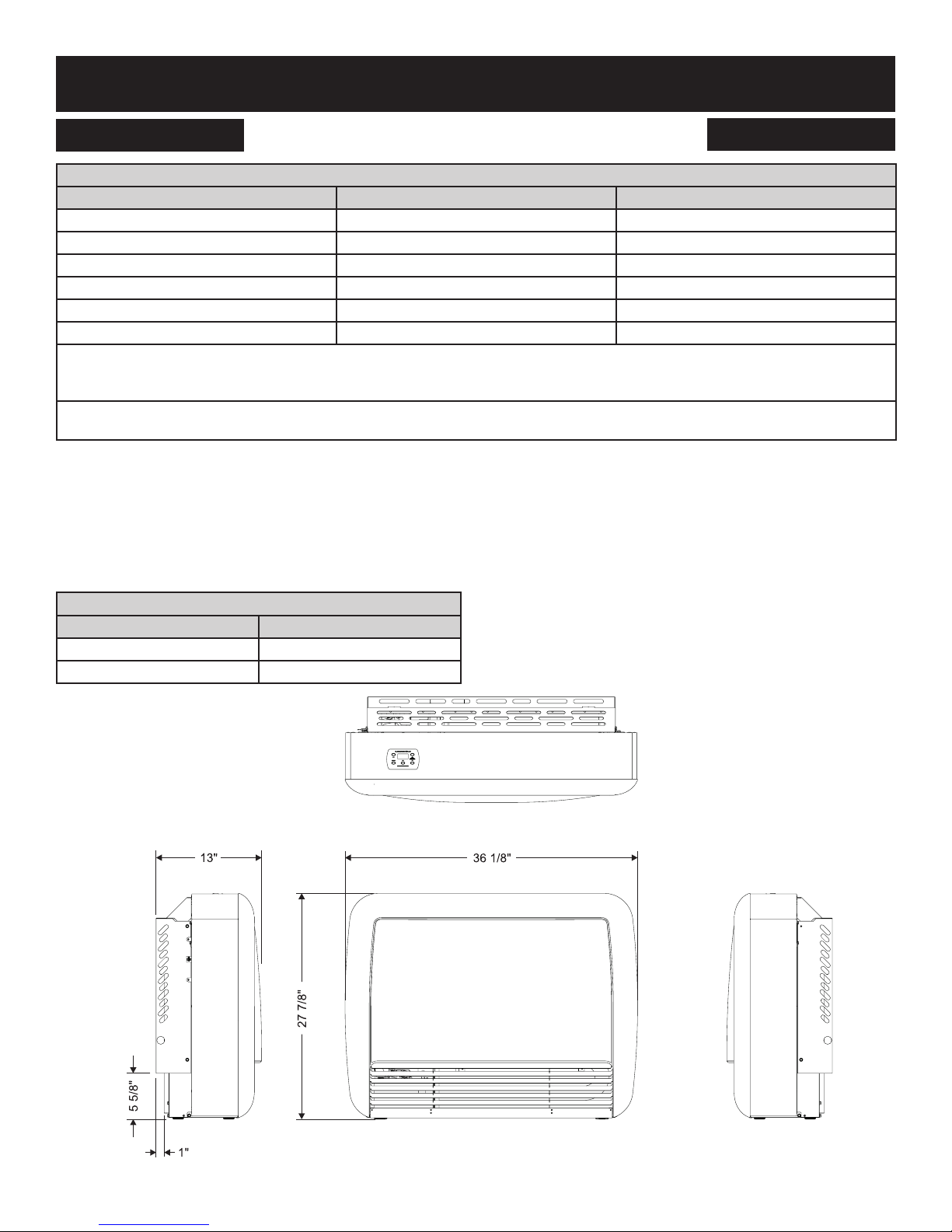
SPECIFICATIONS AND DIMENSIONS
SPECIFICATIONS
Models PVS18(N,P) PVS35(N,P)
Maximum Input BTU/HR (KW/H)* 17,500 (5.13) 35,000 (10.26)
Minimum Input BTU/HR (KW/H)* 8,750 (2.56) 17,500 (5.13)
Height 27-7/8” 27-7/8”
Width 36-1/8” 36-1/8”
Depth with Shroud** 13 13
Gas Inlet (Pipe) 3/8” Pipe 3/8” Pipe
Electrical - The wall furnace comes equipped with a 5 foot (1.5m) 3 pronged cord exiting the rear left side of the wall furnace, for
connection to an approved 115 VAC, 60 Hz, 15A (maximum) wall receptacle. The Minimum Circuit Amp (MCA) is 8A, 920W and with
an accessory heated humidication tray installed, the MCA is 10A, 1150W.
Vent Pipe: 1-1/2 or 2 inch diameter pipe, 50 feet maximum equivalent length. See pages 26 and 29 to 32. The vent termination elbow
does not contribute to the overall vent length measurement.
* Input ratings are based on sea level operation and may vary at different elevations. No orice change is required. The appliance will
de-rate automatically 1.5% per 1,000 feet.
** Add 3-3/8 inches for deep shroud.
All vent and combustion air pipes and ttings must be Schedule 40 PVC, ULC S636 and meet the ANSI/ASTM Standard D1785. Cement
must conform to ASTM Standard D2564. Empire-approved poly pipe with gasketed joints may also be used. Contact your Empire dealer
for availability.
Listed for Category IV venting.
Approved Alternate Vent Systems
Manufacturer Vent System
Duravent PolyPro
Centrotherm InnoFlue
Dimensions - Figure 22
37873-0-0217Page 16
INTRODUCTION
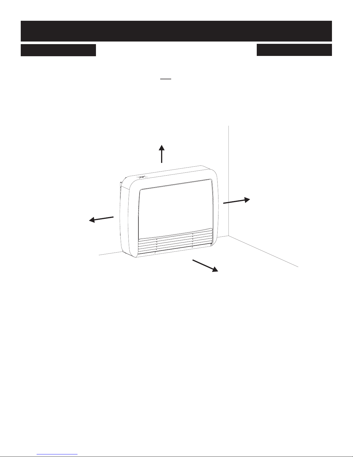
CLEARANCES TO COMBUSTIBLES
Select a location with adequate accessibility clearances for servicing
and proper installation. Locate the wall furnace within 5 feet of a 115
VAC wall receptacle to properly power the wall furnace. Do NOT
use an extension cord.
12”
0”
(8” service area
recommended)
When facing the front of the wall furnace the minimum clearances
from casing to combustible construction are 12" (305mm) on top, 0"
(0mm) on each side and 0” (0mm) from the oor, 0” (0mm) to rear
wall, and 36” (914mm) in front of the wall furnace to walls or furniture.
Notice: It is recommend to leave 8" (203mm) clearance on each
side for servicing, furniture and other easily moved items may be
placed to the sides (not the front) of the wall furnace. See Figure 23.
0”
(8” service area
recommended)
Figure 23
36”
37873-0-0217 Page 17
INTRODUCTION
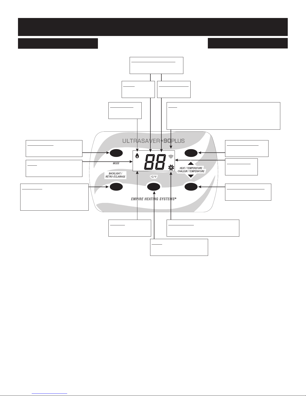
WALL FURNACE DISPLAY
Temperature Display
Shows room temperature
and set temperature
Mode Select
Changes between modes
Off/Remote/Manual/Local
AUX
Shows during operation of
heated tray accessory
Backlight
Activates back lighting of display.
Also shows set temperature and
heat/blower level information in
Local Mode.
Level
Shows heating
level
Flame Icon
Shows when
burners are on
AUX
RESET
RESET
Shows when heater
needs to be reset
Blower Speed
Shows current
blower speed
SET
Shows while adjusting the heat level or set temperature.
Also shows in Local Mode when the backlight button is
pushed when the set temperature is displayed. It will
disappear when the room temperature is displayed.
Up Adjustment
SET
Blower Icon
Shows when room air
blower is running
Adjusts heat level or
set temperature up
Signal Icon
Shows during
Remote Mode
Down Adjustment
Adjusts heat level or
set temperature down
ºC/ºF
Changes temperature units
from Fahrenheit to Celsius
Figure 24
37873-0-0217Page 18
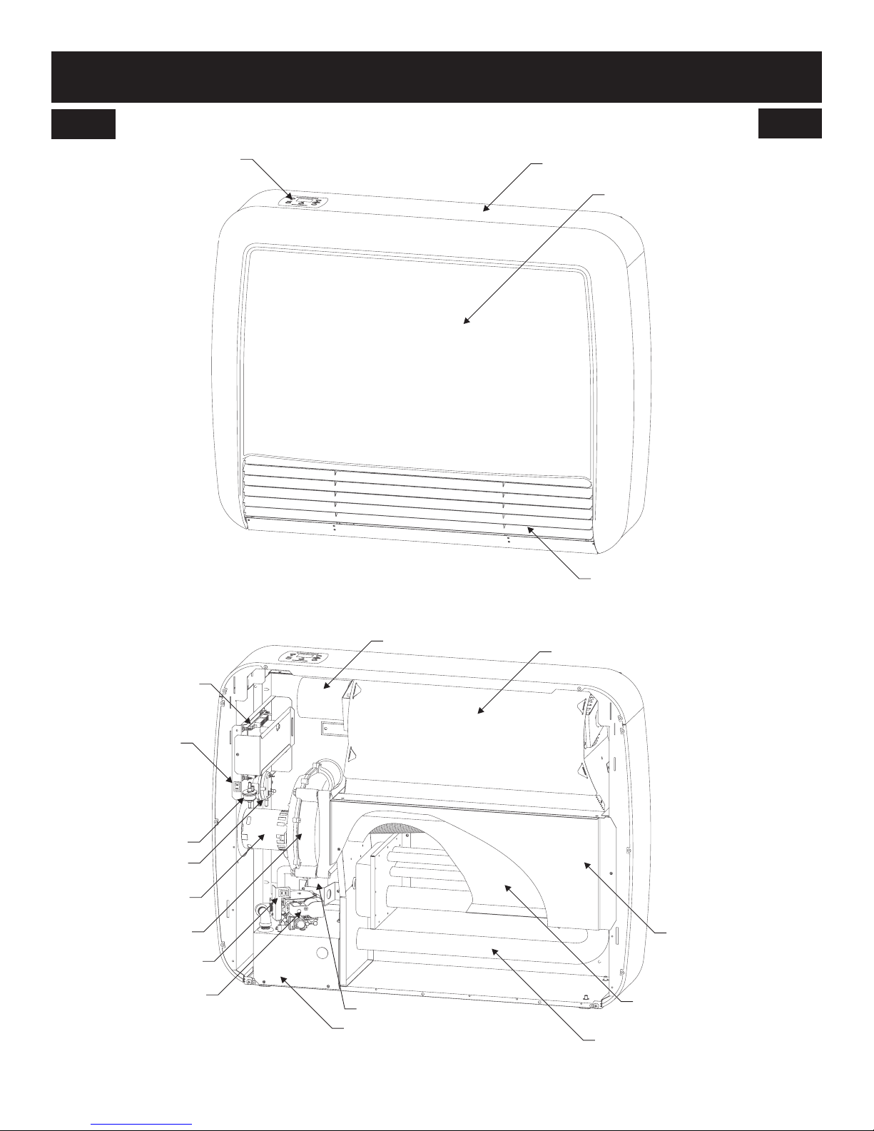
INTRODUCTION
WALL FURNACE COMPONENT ARRANGEMENT - FRONT
DISPLAYPANEL
OUTER CASING
FRONT COVER ASSEMBLY
CONTROL BOARD
MAIN POWER
ON/OFF SWITCH
AIR PRESSURE
TRANSDUCER
PRESSURE SWITCH
INDUCER MOTOR
INDUCER
GAS VALV E
ON/OFF SWITCH
GAS VALV E
Figure 25
BLOWER MOTOR
CONDENSATE TRAP
BURNER COMPARTMENT
FRONT LOUVER ASSEMBLY
CIRCULATING AIR BLOWER
FRONT SHIELD
INNER SHIELD
(SINGLE TUBE UNITS ONLY)
HEAT EXCHANGER
37873-0-0217 Page 19
Figure 26
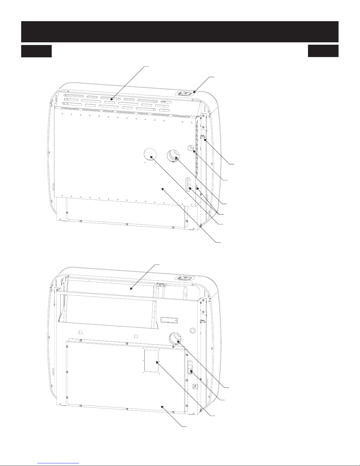
INTRODUCTION
WALL FURNACE COMPONENT ARRANGEMENT - REAR
FILTER COVER
DISPLAYPANEL
TEMPERATURE SENSOR
ALTERNATE ELECTRICAL
CORD OPENING
FLUE OUTLET
Figure 27
FILTER
ALTERNATE GAS LINE OPENINGS
COMBUSTION AIR INTAKE
(DIRECT VENT)
REAR SHROUD
FLUE OUTLET
GAS LINE OPENING
COMBUSTION AIR INTAKE
COMBUSTION AIR DUCT
Figure 28
37873-0-0217Page 20
WALL FURNACE INSTALLATION
MOUNTING THE REAR SHROUD
Tools Needed
Pipe Wrench
Adjustable Wrench
Drill
Tape Measure
10” x 5/16” Nut Driver
Thread Sealant
Level
2-1/2” Diameter Hole Saw for 2” pipe
2” Diameter Hole Saw for 1-1/2” pipe
1” Diameter Hole Saw
Non-corrosive Leak Check Solution
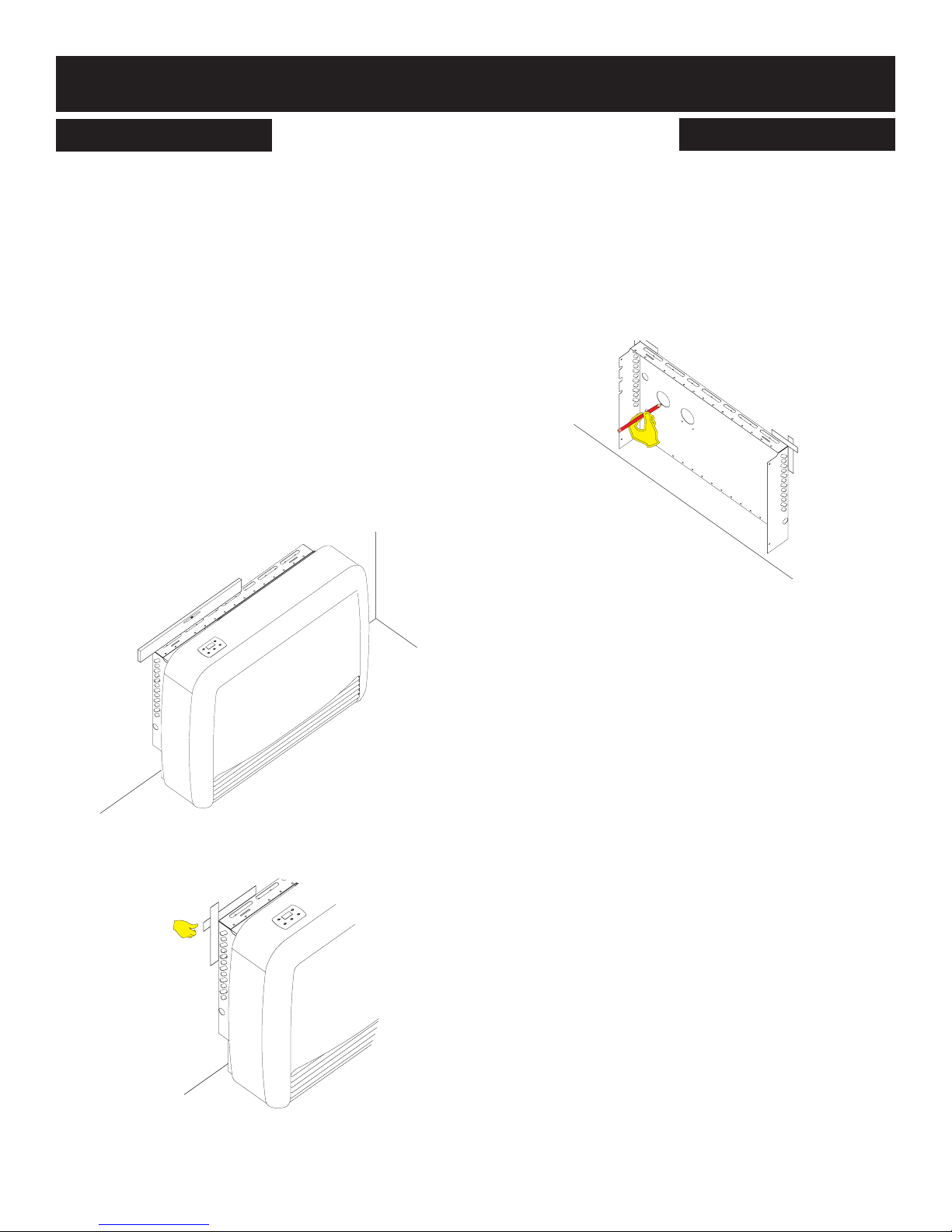
Locating Wall Opening
Locate wall studs and move the wall furnace into position. The shroud
has many holes and can be mounted into 16 or 24 on centers studs.
A series of holes across the top of the rear shroud corresponds to
the mounting holes to aide in aligning the mounting holes with the
wall studs. When mounted directly on the oor, plastic anchors can
be used. Ensure that the vent and gas line openings will be located
between wall studs. Ensure the wall furnace is level, adjust legs on
the bottom of the unit if necessary. See Figure 29.
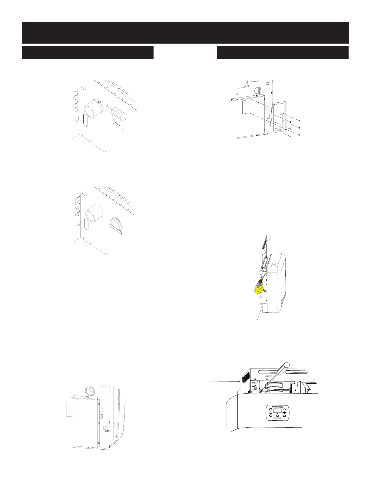
Move the wall furnace away from the wall and remove the rear
shroud from the wall furnace. Remove four 10 x 1/2” hex-head
screws and set aside. Determine if using a direct vent, single ue
venting system. Place the rear shroud against the wall and mark
the vent and gas openings. For single ue installations, mark only
the left hole (as shown in Figure 31). For direct-vent installations,
mark the left and right holes. See Figure 31. The wall opening
required for intake and exhaust pipes is 2-3/8” in diameter within
the circles made above. If the wall furnace is to be wall mounted
above oor level, install per the instructions included with the wall
shroud kit listed on page 15.
Figure 29
Use masking or painter’s tape to mark the location of the two top
corners of the rear shroud against the wall. See Figure 30.
Figure 31
Figure 30
37873-0-0217 Page 21
WALL FURNACE INSTALLATION
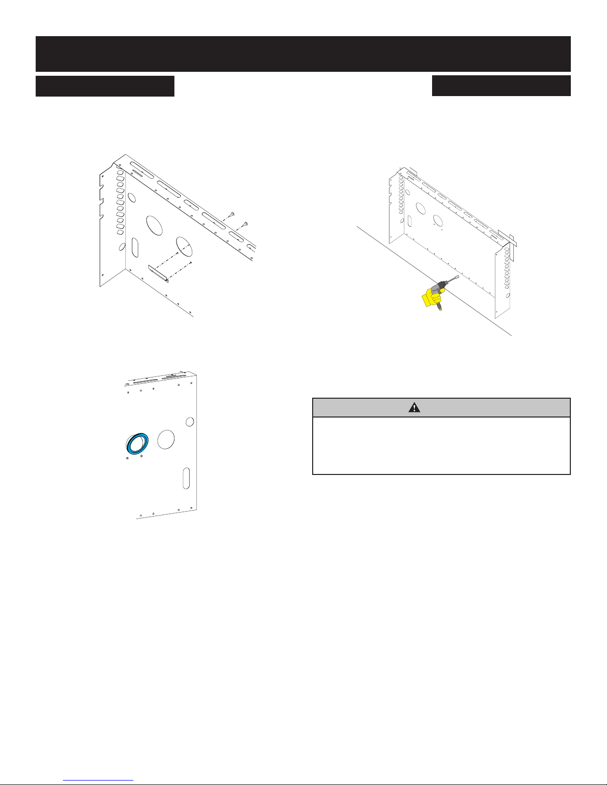
MOUNTING THE REAR SHROUD
Install Pipe Stop Bracket
For direct-vent applications, attach the pipe stop bracket to the
rear shroud with the two 8 x 3/8” phillips pan head screws. See
Figure 32.
Figure 32
Insert the blue intake connector gasket into the inlet air opening
in the rear shroud. See Figure 33.
Installing Rear Shroud
After cutting the opening for the vent and gas line, place the shroud
back into position against the wall and secure in place. The shroud
should be mounted to the wall studs, if possible, using the four 10
x 1-1/2” hex-head screws provided. Two screws in top holes and
two screws in bottom holes. See Figure 34.
Figure 34
If installing the wall furnace on the oor, the rear shroud may be
anchored solidly to the wall using the four plastic anchors (not
provided) and four 10 x 1-1/2” (38mm) hex-head screws (provided).
Figure 33
WARNING
DO NOT use plastic anchors if installing the wall furnace off
of the oor. The wall furnace must be secured to the studs;
it may fall causing damage possible harm. Wall furnaces
installed on the oor may be secured to the wall may use
plastic anchors.
37873-0-0217Page 22
WALL FURNACE INSTALLATION
GAS SUPPLY
All gas piping must be installed in compliance with local codes and
utility regulations. In the absence of local codes the installation
must comply with NFCG NFPA 54/ANSI Z223.1.
Notice: Never use plastic pipe. Check to conrm whether your
local codes allow copper tubing or galvanized.
Where permitted, exible gas connectors must be certied to the
following standards:
— ANS Z21.24 Appliance Connectors of Corrugated Metal Tub-
ing and Fittings
— ANS Z21.45 Assembled Flexible Appliance Connectors of
Other Than All-Metal Construction
The above connectors may be used if acceptable by the authority having jurisdiction. The state of Massachusetts requires that a
exible appliance connector cannot exceed three feet in length.
A drip leg should be installed in the vertical gas supply pipe run to
the wall furnace.
Manual Shut-off Valve
Some local regulations require the installation of a manual shut-off
valve and ground joint union external to the appliance. The shutoff
should be accessible for service and/or emergency use. Consult the
local utility or gas supplier for additional requirements regarding the
placement of the manual shut off valve. Compounds used on
threaded joints of gas piping shall be resistant to the action of liq-
ueed petroleum gases.
Leak Testing
WARNING - FIRE OR EXPLOSION HAZARD
Never test for leaks with an open ame. Check all connections using a commercially available soap solution. A re or
explosion may result causing property damage, personal
injury or loss of life. Failure to follow the safety warnings
exactly could result in serious injury, death or property
damage.
After gas piping to the wall furnace is complete, all connections
must be tested for gas leaks. This includes pipe connections at
the main gas valve, emergency shutoff valve and exible gas connectors (if applicable). The soap and water solution can be applied
on each joint or union using a small paintbrush. If any bubbling is
observed, the connection is not sealed adequately and must be
retightened. Repeat the tightening and soap check process until
the bubbling ceases.
2.
The appliance and its individual shutoff valve must be disconnected from the gas supply piping system during any pressure
testing of that system at test pressures in excess of 1/2 psig.
3. The appliance must be isolated from the gas supply piping
system by closing its individual manual shutoff valve during
any pressure testing of the gas supply piping system at test
pressures equal to or less than 1/2 psig.
High Altitude
The Ultra Saver 90 can be installed to altitudes up to 10,000
feet in the U.S., and in Canada. (No additonal kit is necessary).
Recommended Gas Pipe Diameter
Schedule 40 Pipe
Pipe Length
0-10 feet
0-3 meters
10-40 feet
4-12 meters
40-100 feet
13-30 meters
100-150 feet
31-46 meters
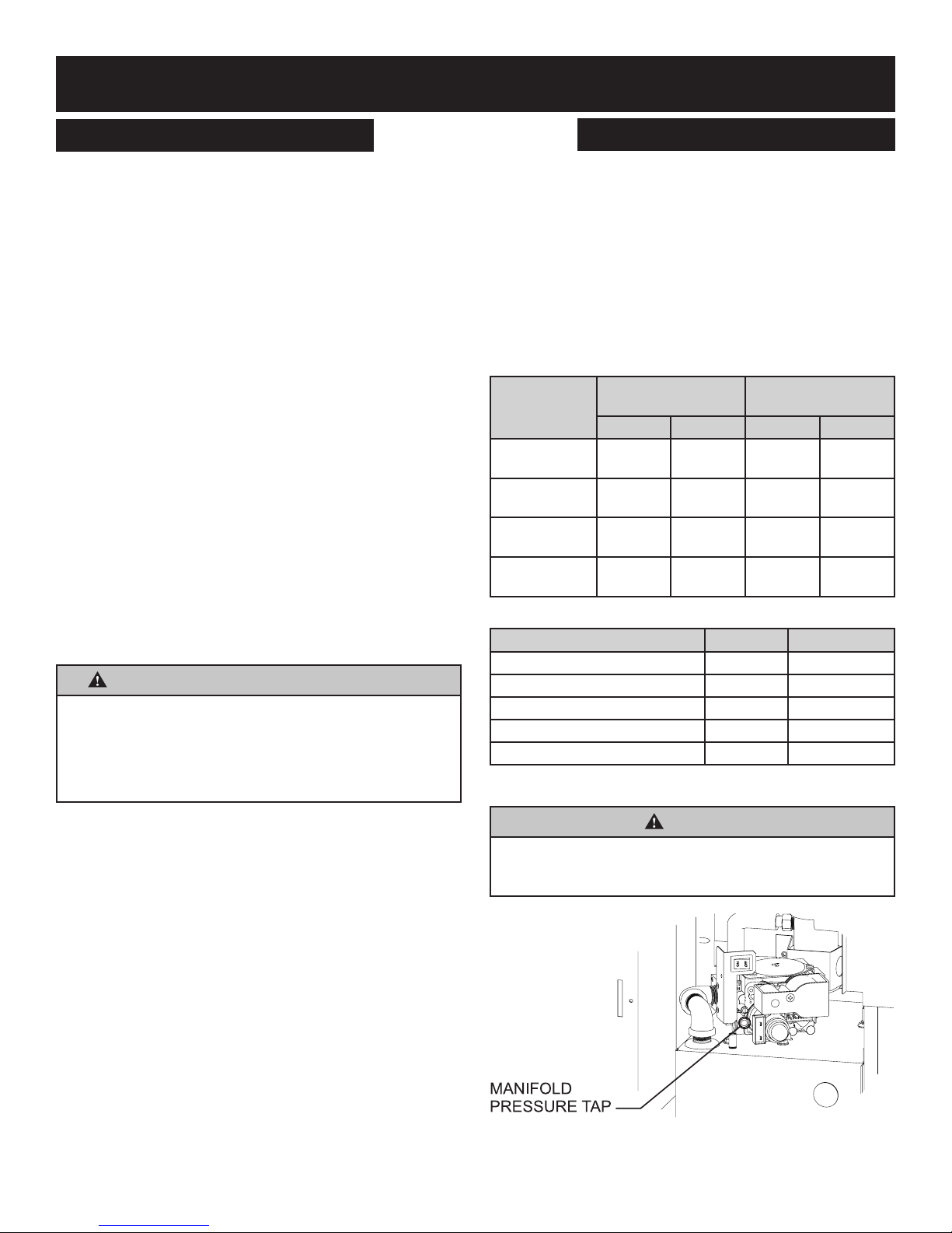
Gas Supply Pressure NAT Gas L.P.
Normal 7.0” w.c. 10.0” w.c.
Minimum 3.5” w.c. 8.0” w.c.
Maximum 10.5” w.c. 13.0” w.c.
Manifold Pressure Hi (Level 5) 3.5” w.c. 7.0” w.c.
Manifold Pressure Low (Level 1) 0.9” w.c. 1.9” w.c.
Gas Connection Installation
Inside Diameter
Nat. L.P. Nat. L.P.
1/2”
12.7 mm
1/2”
12.7 mm
1/2”
12.7 mm
3/4”
19 mm
3/8”
9.5mm
1/2”
12.7mm
1/2”
12.7mm
1/2”
12.7 mm
Table 1
Table 2
Tubing, Type L
Outside Diameter
1/2”
12.7 mm
5/8”
15.9 mm
3/4”
19 mm
7/8”
22.2 mm
3/8”
9.5 mm
1/2”
12.7 mm
1/2”
12.7 mm
3/4”
19 mm
CAUTION
Under no circumstances should the gas supply line to the
appliance be installed in a way that would prevent the appliance from being serviced or inspected.
Notice: When pressure testing the gas supply lines at pressures
greater than ½ psig (14 in. w.c.), the gas supply piping system
must be disconnected from the appliance to prevent damage to
the gas control valve. If the test pressure is less than or equal to
½ psig (14 in. w.c.), close the manual shut-off valve.
Pressure Testing of the Gas Supply System
1. To check the inlet pressure to the gas valve, a 1/8 inch N.P.T.
plugged tapping, accessible for test gauge connection, must
be placed immediately upstream of the gas supply connection
to the appliance.
37873-0-0217 Page 23
Figure 35
WALL FURNACE INSTALLATION
GAS SUPPLY
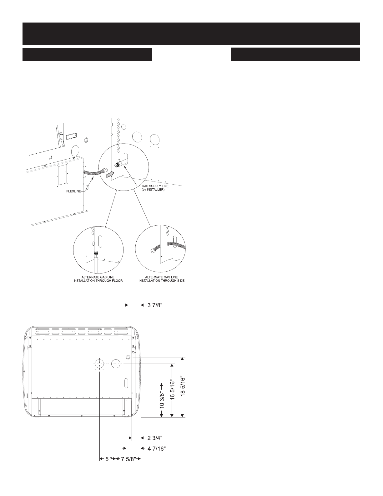
Gas Supply Line to Wall furnace
1. Pull the factory installed exible gas line through the hole in
the back panel. See Figure 36.
2. Connect the gas supply line to exible gas hose. Ensure that
exible gas hose is not kinked after tting gas supply line. Any
excess exible line can be pushed back into the wall furnace.
See Figure 36.
Figure 36
Figure 37
37873-0-0217Page 24

WALL FURNACE INSTALLATION
VENT CLEARANCES
Canadian Installations1 US Installations2 Canadian Installations1 US Installations2
A= Clearance above
grade, veranda, porch,
deck, or balcony
B= Clearance to window or
door that may be open
C= Clearance to
permanently
closed window
D= Vertical clearance
ventilated soft located
above the terminal within
a horizontal distance of
2 feet (61 cm) from the
center line of the terminal
E= Clearance to
unventilated
soft
F= Clearance to
outside corner
G= Clearance
inside corner
H= Clearance to each side
of center line extended
above meter/regulator
assembly
ATTENTION: Vinyl Soft, Vinyl Ceiling, Vinyl Overhang
Disclaimer
Clearances are to heat resistant material (i.e. wood, metal). This
does not include vinyl. Empire Comfort Systems Inc. will not be
held responsible for heat damage caused from terminating under
vinyl overhangs, vinyl ceilings or vinyl ventilated/unventilated softs.
12-in (30cm) 12-in (30cm) I= Clearance to service
6-in (15cm) for appliances ≤ 10,000 Btuh
(3kW), 12-in (30cm) for
appliances > 10,000
Btuh (3kW) and ≤
100,000 Btuh (30kW),
36-in (91cm) for appliances > 100,000 Btuh
(30kW)
12-in (30cm) 12-in (30cm)
12-in (30cm) 12-in (30cm)
12-in (30cm) 12-in (30cm)
12-in (30cm) 12-in (30cm)
12-in (30cm) 12-in (30cm)
3ft (91cm) within a
height 15ft (4.5m)
above the meter/regulator assembly
6-in (15cm) for appli-
ances ≤ 10,000 Btuh
(3kW), 9-in (23cm) for
appliances > 10,000
Btuh (3kW) and ≤
50,000 Btuh (15kW),
12-in (30cm) for appliances > 50,000 Btuh
(15kW)
3ft (91cm)
regulator vent outlet 3ft (91cm) 6ft
J= Clearance to nonme-
chanical air supply
inlet to building or the
combustion air inlet to
any other appliance
K= Clearance to a
mechanical air
supply inlet
L= Clearance above
paved sidewalk or
paved driveway
located on public
property
M= Clearance under
veranda, porch
deck, or balcony
1 In accordance with the current CSA B149.1, Natural Gas and Propane
Installation Code
2 In Accordance with the current ANSI Z223.1/NFPA 54, National Fuel Gas
Code
† A vent shall not terminate directly above a sidewalk or paved driveway that
is located between two single family dwellings and serves both dwellings
‡ Permitted only if veranda,, porch, deck, or balcony is fully open on a mini-
mum of two sides beneath the oor.
* For clearances not specied in ANSI Z223.1/NFPA 54 or CSA B149.1, one
of the following shall be indicated:
Clearance in accordance with local installation codes and the requirements of the
gas supplier.
6-in (15cm) for appli-
ances ≤ 10,000 Btuh
(3kW), 12-in (30cm) for
appliances > 10,000
Btuh (3kW) and ≤
100,000 Btuh (30kW),
36-in (91cm) for appliances > 100,000 Btuh
(30kW)
6ft (1.83m)
7ft (2.13m) † 7ft (2.13m) †
12-in (30cm) ‡ 12-in (30cm) ‡
6-in (15cm) for appli-
ances ≤ 10,000 Btuh
(3kW), 9-in (23cm) for
appliances > 10,000
Btuh (3kW) and ≤
50,000 Btuh (15kW),
12-in (30 cm) for appliances > 50,000 Btuh
(15kW)
3ft (91cm) above if
within 10ft (3m)
horizontally
37873-0-0217 Page 25
Figure 38
WALL FURNACE INSTALLATION
VENTING REQUIREMENTS
WARNING
This appliance must not be vented with any other appliances, even if that appliance is of the condensing type. Common venting can result in severe corrosion of other appliances or their venting and can allow combustion gases to
escape through such appliances or vents. Do not vent the
wall furnace into a replace chimney or building chase. The
ue exhaust pipe must be vented outside.
WARNING
Upon completion of the installation, carefully inspect the entire ue system to ensure it is properly sealed. DO NOT use
any vent material other than what is specied in this manual.
Leaks in the ue system can result in serious personal injury
or death due to exposure of ue products, including carbon
monoxide.
The UltraSaver is classied as a “Category IV” appliance, which
requires special venting materials and installation procedures.
Installations can be Conventional (one-pipe) and Direct Vent
(two-pipe). Venting must be completed with 1-1/2 or 2 inch diameter pipe. In selecting a location for installation, it is necessary to
provide adequate clearances for servicing and proper installation.
All vent and combustion air pipes and ttings must be Schedule
40 PVC, ULC S636 and meet the ANSI/ASTM Standard D1785.
Cement must conform to ASTM Standard D2564.
Installation in Canada must conform to the requirements of CSA
B149 code. Vent systems must be composed of pipe, ttings,
cements, and primers listed to ULC S636. In Canada, the primer
and cement must be of the same manufacturer as the vent
system; do not mix primers and cements from one manufacturer
with a vent system from a different manufacturer. Follow the
manufacturer’s instructions the use of primer and cement and
never use primer or cement beyond its expiration date.
The safe operation, as dened by ULC S636, of the vent system
is based on following these installation instructions, the vent
system manufacturer’s installation instructions, and proper use
of primer and cement. Acceptability under Canadian standard
CSA B149 is dependent upon full compliance with all installation
instructions. Under this standard, it is recommended that the vent
system be checked once a year by qualied service personnel.
The authority having jurisdiction (gas inspection authority,
municipal building department, re department, etc) should be
consulted before installation to determine the need to obtain a
permit.
The maximum vent length is 40 feet equivalent with (3) 90°
elbows. The minimum vent length is 12 inches. Each 90°
elbow used in the vent system will be the equivalent to 3 feet,
and each 45° elbow is equivalent to 1.5 feet, which should be
added to the overall vent length.
1. The installation must conform with, as applicable:
A. A non-metallic venting system for use in Canada shall
be listed to the Standard for Type BH Gas Venting
Systems, ULC S636.
B. A maintenance schedule, when a means is provided to
neutralize condensate, if required.
C. Periodic cleaning of the condensate collection and
disposal system(s), if required.
D. For Category IV appliances:
(1) When the manufacturer supplies the venting
system, the instructions shall include a parts list
and instructions covering the installation of properly
identied parts to provide for the venting of the vent
gases to the outdoors.
(2) When the parts for venting the vent gases are not
provided by the manufacturer and they are specic
types listed by a nationally recognized testing
agency, these instructions shall clearly identify and
specify the use of the specic parts.
2. For Category IV appliances, the venting system shall be
installed in accordance with the appliance manufacturer’s
instructions.
3. Instructions for proper venting installation:
A. Horizontal portions of the venting system shall:
(1) Be supported to prevent sagging. The methods of
and intervals for supports shall be specied in the
installation manuals.
(2) Slope upwards not less than 1/4 in/ft (21 mm/m)
from the appliance to the vent terminal.
(3) Category IV appliances shall be installed so as to
prevent accumulation of condensate in the venting
system.
4. Category IV appliance installations shall provide a means for
removal of condensate.
5. For appliance installation instructions accompanying a direct
vent appliance or other appliance that can utilize a side wall
vent system shall include information on where the vent
terminal can and cannot terminate, including:
For Category IV appliances, the following statement:
The vent for this appliance shall not terminate:
(a) Over public walkways; or
(b) Near soft vents or crawl space vents or other
areas where condensate or vapor could create a
nuisance or hazard or cause property damage; or
(c) Where condensate vapor could cause damage or
could be detrimental to the operation of regulators,
relief valves, or other equipment.
6. Non-metallic venting systems shall not interchange
components with another listed or unlisted metallic or
nonmetallic vent systems.
Attention: Check local codes for venting requirements.
NOTE: IPEX System 636 Flue Gas Venting Adaptor is provided.
Installer to check for adhesive material requirements.
Empire approved poly pipe with gasketed joints may also be used.
Contact your Empire dealer for availability. The use of vent tubes
not approved by the manufacturer may result in unsatisfactory performance.
37873-0-0217Page 26
WALL FURNACE INSTALLATION
VENTING
The ue exhaust pipe and inlet air pipe should be located between
wall studs. If an existing unit is being replaced, the ue exhaust
and inlet pipes may be run continuously through the existing ue
pipe or wall opening. See page 15 for special termination kits. The
required opening for venting is 1-7/8 inch in diameter for 1-1/2 inch
pipe, and 2-3/8 inch diameter for two inch pipe.
The ue outlet must be at least twelve inches from any opening
which ue gases could enter the building. See Figure 38. The ue
outlet must be a minimum distance of three feet from any pressure
regulator.
The bottom of the exhaust vent terminal and the air intake must
be located at least twelve inches above grade or the maximum
snow level.
The pipe must be supported every three feet on horizontal runs
and every 10 feet on vertical runs. All horizontal runs must be
pitched ¼ inch per foot towards the wall furnace.
Notice: If the vent run dips or sags, condensation may become
trapped and cause the wall furnace to not operate properly.
The minimum vent length protruding from outside the wall is ten
inches. For two-pipe installation, a minimum distance of ve inches from pipe centers and maximum distance of 24 inches must be
maintained between the pipes. See Page 31.
Maximum Vent Length is 50 feet. Each 90° elbow used in the
vent system will be the equivalent to three feet, and each 45°
elbow is equivalent to 1.5 feet, which should be added to the
overall vent length. The vent terminal does not contribute to the
overall vent length measurement.
Notice: If vent length requirements are not followed, the wall
furnace will not operate properly.
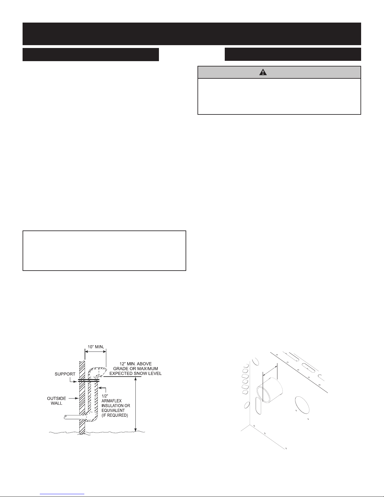
Vent Freezing Protection
When the vent pipe is exposed to temperatures below freezing
(i.e. when it passes through unheated spaces, chimneys, etc.) The
pipe must be insulated with 1/2 inch thick sponge rubber insulation, Armaex-type insulation or equivalent (Ameraex is a registered trademark of Amaracell). Insulating pipe is important to avoid
condensate icing. See Figure 39.
WARNING
The nearest point of the vent cap should be a minimum
horizontal distant of three feet (0.91m) from any pressure
regulator. In case of regulator malfunction, the three feet
(0.91m) distance will reduce the chance of gas entering the
vent cap.
Notice: Clean all debris from the inside of the ue pipe prior
to applying the glue and nal assembly of the pipe. Since the
condensate is designed to ow back to the appliance this debris
will be carried to the condensate trap resulting in a clog. An “A2”
error will appear on the display panel if this happens. The clog,
and the work required to x it, can be easily prevented by pulling
a wet cloth through the pipe prior to applying the glue and nal
assembly.
Install Vent Termination and Piping
The UltraSaver may be installed with up to 50’ equivalent length
venting.
Notice: For each 45° elbow installed in the run, the length
of the run MUST be reduced by 1.5 feet (45 cm). Reduce the
length of the run three feet (91.4 cm) for every 90° elbow. The
vent terminal elbow does not contribute to the overall vent
length measurement.
See pages 29 through 32 for vent termination and vent run examples and requirements.
This unit is vented directly out the back using 1-1/2” or 2” PVC
pipe. See Figure 38 for exterior vent hole location.
If 1-1/2” pipe is used, it must be enlarged to 2” pipe prior to exiting the wall into the shroud.
If venting out the back through the wall is not possible (such as
in a basement) the vent pipes may be run in front of the wall (left,
right, or up) inside of the room using an optional deep shroud.
See page 15.
When venting through the wall, be sure to leave 2-3/8” (51mm)
of ue pipe extending through the rear shroud into the room for
connection to the inducer. See Figure 40.
Figure 39
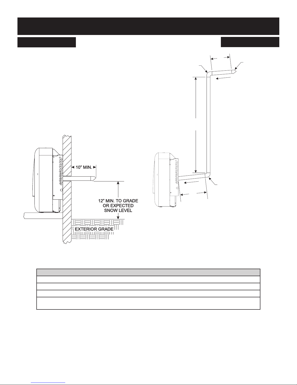
The minimum ue length off the wall is 10”.
The bottom of the exhaust vent terminal and the air intake shall
be located at least 12 inches above grade or expected snow level.
37873-0-0217 Page 27
2 3/8”
(60mm)
Figure 40
WALL FURNACE INSTALLATION
VENTING
To prevent ue pipe from pushing back into the wall, place a hose
clamp on the pipe against the wall and tighten. See Figure 41.
Figure 41
For direct-vent installations, the inlet air pipe will only extend
1/4” through the wall into the rear shroud. The inlet pipe will butt
against the stopping ange provided with the air pipe kit. See
Figure 42.
Attach the transition box to the back of the wall furnace with six
10 x 1/2” hex-head screws. See Figure 44.
Figure 44
Carefully push the wall furnace back into position against the rear
shroud and connect the ue pipe to the inducer.
Attach the wall furnace to the rear shroud by using four 10 x 1/2”
(13mm) hex-head screws previously removed (see page 21). See
Figure 45. Do not tighten the screws.
Reinstall the lter door by inserting the lter door tabs into the
two receiving slots on top of the rear shroud. Close the lter door,
then adjust the wall furnace positions to minimize the gap be-
tween the wall furnace casing and the lter door. Tighten the four
wall shroud screws to secure the wall furnace in place.
Figure 42
Due to the high efciency of the Ultra Saver, condensate will form
in the heat exchanger and ue pipe. A condensate trap and drain
tube are provided to dispose of the condensate to a nearby oor
drain. An optional humidication tray is also available to evapo-
rate the condensate back into the room as humidity instead of
draining it away from the wall furnace. See page 15.
If draining the condensate away from the wall furnace, route the
condensate drain tube provided in the instruction envelope to the
elbow on the tube sticking through the back of the wall furnace
to a nearby drain. See Figure 43. The elbow may be rotated to
direct the hose to either side or straight down. Eliminate all sags
or dips as they may prevent drainage. An optional drain tube
extension kit and optional condensate pump kit accessory are
available. See page 15.
Notice: Due to the mildly acidic nature of wall furnace condensation, check with local authorities to determine if a ph neutralizing
process may be required.
Figure 45
Notice: For oor mounted wall furnaces, ensure the adjustable
legs are all on the oor.
To complete inside installation open the lter door and, tighten
the inducer hose clamp with a 10-inch 5/16” nut driver. See
Figure 46.
Figure 43
Figure 46
37873-0-0217Page 28
OUNTED)
SLOPE
SLOPE
WALL FURNACE INSTALLATION
VENT EXAMPLES FOR SINGLE FLUE
Max Vent Run - 50 ft. Equivalent
When installing a horizontal vent termination, the minimum vent
length protruding from the outside wall is 10 inches (304mm). See
Figure 47.
For venting cap, exhaust with 45° elbow.
Notice: Horizontal discharge 45° elbow must be pointed down-
ward. See Figure 47.
Notice: All horizontal runs require a 1/4” per foot rise to run con-
densation back to the wall furnace.
Notice: For each 45° elbow installed, the length of the run
MUST be reduced by 1.5 feet (45 cm). Reduce the length of the
run three feet (91.4 cm) for every 90° elbow. The vent terminal
elbow does not contribute to the overall vent length measure-
ment.
90
3 FEET
ELBOW°
37’
(11.3m)
5’
(1.5m)
2’
(61.0cm)
FIRST 90° ELBOW
3 FEET
VENT TERMINAL
45° ELBOW
(NOTC
Figure 48
Example Calculation Max Vent Run 50 feet
Figure 48 displays a single ue (one-pipe) installation. The rst
90° elbow must be considered into the total vent length. The
equivalent length of the second 90° elbow also needs to be add-
Figure 47
Single Flue - Straight Out Back
EVL = Equivalent Vent Length
EVL must be greater than or equal to 1’ and less than or equal to 50’
EVL = 5’ straight pipe + 90º elbow + 37’ straight pipe + 90º elbow + 2’ straight pipe = 50’
EVL =
5’
(straight pipe)
Table 3 - Equivalent Vent Length Example (See Figure 48)
+
3’
(90º elbow)
+
(straight pipe)
ed to the total length, but the third elbow does not since it is the
ue terminal. The total horizontal vent length of the ue system
is seven feet, and the total vertical length is 37 feet. The two 90°
elbows are equivalent to six feet, bringing the total to 50 feet.
37’
+
3’
(45º elbow)
+
(straight pipe)
2’
= 50’
37873-0-0217 Page 29
 Loading...