

Empire Comfort Systems VFD26FP70L10, VFD26FM20NN-2, VFD26FM30NP-2, VFD26FM30WN-2, VFD26FM30WP-2 Installation Instructions And Owner's Manual
...
INSTALLATION INSTRUCTIONS
AND
OWNER'S MANUAL
Vent-Free Gas Fireplaces
This appliance may be installed in an aftermarket,
permanently located, manufactured (mobile) home,
where not prohibited by local codes.
This appliance is only for use with the type of gas indicated on the rating plate. This appliance is not convertible for use with other gases.
WARNING
If the information in these instructions are not followed exactly, a re or explosion may result causing property damage, personal injury or loss of life.
— Do not store or use gasoline or other ammable
vapors and liquids in the vicinity of this or any
other appliance.
— WHAT TO DO IF YOU SMELL GAS
• Do not try to light any appliance.
• Do not touch any electrical switch; do not use
any phone in your building.
• Immediately call your gas supplier from a
neighbor’s phone. Follow the gas supplier’s
instructions.
• If you cannot reach your gas supplier, call the
re department.
— Installation and service must be performed by a
qualied installer, service agency or the gas supplier.
UNVENTED
GAS FIREPLACE
MODELS
VFD26FM(2,3)0(N,W,C)(N,P)-2
VFD26FP(2,3)0L(N,P)-2
VFD26FP70L(N,P)-1
VFD26FP30L10(N,P)-3
VFD26FP70L10(N,P)-1
Installer: Leave this manual with the appliance.
Consumer: Retain this manual for future reference.
This is an unvented gas-red heater. It uses air (oxygen) from the room in which it is installed. Provisions
for adequate combustion and ventilation air must be
provided. Refer to pages 9 and 10.
WATER VAPOR: A BY-PRODUCT OF UNVENTED
ROOM HEATERS
Water vapor is a by-product of gas combustion. An
unvented room heater produces approximately one
ounce (30ml) of water for every 1,000 BTU's (.3KW's)
of gas input per hour. Refer to page 8.
WARNING
If not installed, operated and maintained in accordance with the manufacturer's instructions, this
product could expose you to substances in fuel or
from fuel combustion which can cause death or serious illness.
Page 1

TABLE OF CONTENTS
SECTION PAGE
IMPORTANT SAFETY INFORMATION ......................................................................................... 3
SAFETY INFORMATION FOR USERS OF LP-GAS ..................................................................... 4
INTRODUCTION ........................................................................................................................... 5
BUILT-IN FIREPLACE INSTALLATION ......................................................................................... 6
FIREPLACE DIMENSIONS ........................................................................................................... 7
SPECIFICATIONS ......................................................................................................................... 8
WATER VAPOR: A BY-PRODUCT OF UNVENTED ROOM HEATERS ........................................ 8
PROVISIONS FOR ADEQUATE COMBUSTION & VENTILATION AIR ...................................9-10
CONNECTING THE GAS ............................................................................................................ 10
GAS SUPPLY .............................................................................................................................. 11
CLEARANCES ............................................................................................................................ 12
COMBUSTIBLE MATERIAL ........................................................................................................12
INSTALLATION OF FIREPLACE AND MANTEL ....................................................................13-14
OUTER TRIM INSTRUCTIONS................................................................................................... 15
HOOD INSTRUCTIONS .............................................................................................................. 15
LOG PLACEMENT ...................................................................................................................... 16
PLACEMENT OF GLOWING EMBERS (ROCK WOOL)............................................................. 17
OPERATION INSTRUCTIONS/FLAME APPEARANCE.............................................................. 18
MAINTENANCE ........................................................................................................................... 18
10,000 BTU MILLIVOLT LIGHTING INSTRUCTIONS .................................................................19
MILLIVOLT LIGHTING INSTRUCTIONS ..................................................................................... 20
INTERMITTENT PILOT LIGHTING INSTRUCTIONS .................................................................21
HYDRAULIC THERMOSTAT LIGHTING INSTRUCTIONS ......................................................... 22
PILOT FLAME CHARACTERISTICS .....................................................................................23-24
MAIN BURNER AND THERMOSTAT OPERATION ....................................................................25
MILLIVOLT WIRING ....................................................................................................................26
MILLIVOLT TROUBLESHOOTING ..............................................................................................27
IP ELECTRONIC SYSTEM OPERATING INSTRUCTIONS ........................................................ 28
IP ELECTRONIC SYSTEM WIRING DIAGRAM ......................................................................... 29
INTERMITTENT CONTROL SYSTEM TROUBLESHOOTING ..............................................30-32
JUNCTION BOX WIRING INSTALLATION INSTRUCTIONS ...................................................... 33
PARTS LIST ............................................................................................................................34-35
PARTS VIEW ............................................................................................................................... 36
FBBX BLOWER KIT EXTENSION INSTALLATION INSTRUCTIONS ...................................37-38
FBB4 OPTIONAL VARIABLE SPEED BLOWER ......................................................................... 38
FPP26E OPTIONAL BRICK LINER KIT INSTALLATION INSTRUCTIONS ................................ 39
MASTER PARTS DISTRIBUTOR LIST ....................................................................................... 40
HOW TO ORDER REPAIR PARTS .............................................................................................40
WARRANTY ................................................................................................................................41
APPLIANCE SERVICE HISTORY ..........................................................................................42-43
30816-7-0814Page 2
IMPORTANT SAFETY INFORMATION
THIS IS A HEATING APPLIANCE
DANGER: Indicates a hazardous situation which, if not avoided, will
result in death or serious injury.
WARNING: Indicates a hazardous situation which, if not avoided,
could result in death or serious injury.
CAUTION: Indicates a hazardous situation which, if not avoided,
could result in minor or moderate injury.
NOTICE: Addresses practices not related to personal injury.
• An unvented room heater having an input rating of more than
6,000 Btu per hour shall not be installed in a bathroom
• An unvented room heater having an input rating of more than 10,000
Btu per hour shall not be installed in a bedroom or bathroom.
• Due to high temperatures, the appliance should be located out of
trafc and away from furniture and draperies.
• Children and adults should be alerted to the hazard of high surface
temperature and should stay away to avoid burns or clothing
ignition.
• Young children should be carefully supervised when they are in
the same room with the appliance.
• Do not place clothing or other ammable material on or near the
appliance.
• Avoid the use of scented air fresheners (plug in type air
fresheners, etc. ) while the log set is in operation. Air fresheners
produce a residue in the air similar to candles and may produce
a soot like substance.
• Avoid the use of scented or decorative candles while the log
set is in operation. Candles produce a residue in the air that
creates a soot like substance. Burning candles while the log
set is operating magnies the problem. It should be noted that
candles, in general, produce soot. The amount of time burned
and the quantity of candles burned will determine the amount
of soot produced and deposited.
• Installation and repair should be done by a QUALIFIED SERVICE
PERSON. This appliance should be inspected before use and at
least annually by a professional service person. More frequent
cleaning may be required due to excessive lint from carpeting,
bedding materials, etc. It is imperative that control compartments,
burners and circulating air passageways of the appliance be
kept clean.
• DO NOT use this room heater if any part has been under water.
Immediately call a qualied service technician to inspect the
room heater and to replace any part of the control system and
any gas control which has been under water.
• You must operate heater with replace screen in place.
• Do not place trash, logs or other articles on the log set during
operation.
• During manufacturing, fabricating and shipping, various
components of this appliance are treated with certain oils, lms
or bonding agents. These bonding agents are not harmful but
may produce annoying smoke and smells as they are burned
off during initial operation of the appliance. This is a normal
temporary occurrence. A window should be opened during the
initial bake out period.
• Correct installation of the ceramic ber logs, proper location of
the heater and annual cleaning are necessary to avoid potential
problems with sooting. Sooting, resulting from improper
installation or operation, can settle on surfaces outside the
replace. See instructions for proper installation.
• WARNING: Do not allow fans to blow directly into the
replace. Avoid any drafts that alter burner ame patterns.
• WARNING: Do not use a blower insert, heat exchanger insert
or other accessory not approved for use with this heater.
• WARNING! This replace needs fresh air for ventilation to
run properly. This replace has an ODS (oxygen depletion
sensor) which will shut down the heater if adequate fresh air is
not available. See troubleshooting section in the instructions.
• WARNING: DO NOT operate this appliance unless all
components including logs, burners, and controls are in good
working condition. Never operate this appliance if any log or
twig is broken, or out of their intended position. Refer to the
Log set placement instructions for correct log and twig
positioning.
Replacement components are available through your local
dealer as indicated in the How to Order Repair Parts section of
the appliance manual.
• Keep appliance area clear and free from combustible materials,
gasoline and other ammable vapors and liquids.
• WARNING: Failure to keep the primary air opening(s) of the
burner(s) clean may result in sooting and property damage.
WARNING
When used without adequate combustion and ventilation air,
heater may give off CARBON MONOXIDE, an odorless, poisonous gas.
Do not install heater until all necessary provisions are
made for combustion and ventilation air. Consult the written instructions provided with the heater for information
concerning combustion and ventilation air. In the absence
of instructions, refer to the National Fuel Gas Code, ANSI
Z223.1/NFPA 54, Air for Combustion and Ventilation, or
applicable local codes.
This heater is equipped with a PILOT LIGHT SAFETY SYSTEM designed to turn off the heater if not enough fresh air
is available.
DO NOT TAMPER WITH PILOT LIGHT SAFETY SYSTEM!
If heater shuts off, do not relight until you provide fresh air.
If heater keeps shutting off, have it serviced. Keep burner and
control compartment clean.
CARBON MONOXIDE POISONING MAY LEAD TO DEATH.
Early signs of carbon monoxide poisoning resemble the u,
with headache, dizziness and/or nausea. If you have these
signs, heater may not be working properly. Get fresh air at
once! Have heater serviced.
Some people — pregnant women, persons with heart or lung
disease, anemia, those under the inuence of alcohol , those
at high altitudes — are more affected by carbon monoxide
than others.
The pilot light safety system senses the depletion of oxygen
at its location. If this heater is installed in a structure having a
high vertical dimension, the possibility exists that the oxygen
supply at the higher levels will be less than that at the heater.
In this type of application, a fan to circulate the structure air will
minimize this effect. The use of this fan will also improve the
comfort level in the structure. When a fan is used to circulate
air, it should be located so that the air ow is not directed at
the burner.
30816-7-0814 Page 3

SAFETY INFORMATION FOR USERS OF LP-GAS
Propane (LP-Gas) is a ammable gas which can cause res
and explosions. In its natural state, propane is odorless and
colorless. You may not know all the following safety precautions which can protect both you and your family from an
accident. Read them carefully now, then review them point by
point with the members of your household. Someday when
there may not be a minute to lose, everyone's safety will depend
on knowing exactly what to do. If, after reading the following
information, you feel you still need more information, please
contact your gas supplier.
LP-GAS WARNING ODOR
If a gas leak happens, you should be able to smell the gas because of the odorant put in the LP-Gas.
That's your signal to go into immediate action!
• Do not operate electric switches, light matches, use your
phone. Do not do anything that could ignite the gas.
• Get everyone out of the building, vehicle, trailer, or area.
Do that IMMEDIATELY.
• Close all gas tank or cylinder supply valves.
• LP-Gas is heavier than air and may settle in low areas
such as basements. When you have reason to suspect
a gas leak, keep out of basements and other low areas.
Stay out until reghters declare them to be safe.
• Use your neighbor's phone and call a trained LP-Gas service
person and the re department. Even though you may not
continue to smell gas, do not turn on the gas again. Do
not re-enter the building, vehicle, trailer, or area.
• Finally, let the service man and reghters check for escaped gas. Have them air out the area before you return.
Properly trained LP-Gas service people should repair the
leak, then check and relight the gas appliance for you.
NO ODOR DETECTED - ODOR FADE
Some people cannot smell well. Some people cannot smell
the odor of the chemical put into the gas. You must nd
out if you can smell the odorant in propane. Smoking can
decrease your ability to smell. Being around an odor for a time
can affect your sensitivity or ability to detect that odor. Sometimes other odors in the area mask the gas odor. People may
not smell the gas odor or their minds are on something else.
Thinking about smelling a gas odor can make it easier to smell.
The odorant in LP-gas is colorless, and it can fade under
some circumstances. For example, if there is an underground
leak, the movement of the gas through soil can lter the odorant. Odorants in LP-Gas also are subject to oxidation. This
fading can occur if there is rust inside the storage tank or in
iron gas pipes.
The odorant in escaped gas can adsorb or absorb onto or
into walls, masonry and other materials and fabrics in a room.
That will take some of the odorant out of the gas, reducing its
odor intensity.
LP-Gas may stratify in a closed area, and the odor intensity
could vary at different levels. Since it is heavier than air, there
may be more odor at lower levels. Always be sensitive to the
slightest gas odor. If you detect any odor, treat it as a serious
leak. Immediately go into action as instructed earlier.
• Learn to recognize the odor of LP-gas. Your local LP-Gas
Dealer can give you a "Scratch and Sniff" pamphlet. Use it
to nd out what the propane odor smells like. If you suspect
that your LP-Gas has a weak or abnormal odor, call your
LP-Gas Dealer.
• If you are not qualied, do not light pilot lights, perform
service, or make adjustments to appliances on the LP-Gas
system. If you are qualied, consciously think about the odor
of LP-Gas prior to and while lighting pilot lights or performing
service or making adjustments.
• Sometimes a basement or a closed-up house has a musty
smell that can cover up the LP-Gas odor. Do not try to light
pilot lights, perform service, or make adjustments in an area
where the conditions are such that you may not detect the
odor if there has been a leak of LP-Gas.
• Odor fade, due to oxidation by rust or adsorption on walls
of new cylinders and tanks, is possible. Therefore, people
should be particularly alert and careful when new tanks or
cylinders are placed in service. Odor fade can occur in new
tanks, or reinstalled old tanks, if they are lled and allowed
to set too long before relling. Cylinders and tanks which
have been out of service for a time may develop internal
SOME POINTS TO REMEMBER
rust which will cause odor fade. If such conditions are sus-
pected to exist, a periodic sniff test of the gas is advisable.
If you have any question about the gas odor, call your
LP-gas dealer. A periodic sniff test of the LP-gas is a
good safety measure under any condition.
• If, at any time, you do not smell the LP-Gas odorant and
you think you should, assume you have a leak. Then take
the same immediate action recommended above for the
occasion when you do detect the odorized LP-Gas.
• If you experience a complete "gas out," (the container is
under no vapor pressure), turn the tank valve off immediately.
If the container valve is left on, the container may draw in
some air through openings such as pilot light orices. If this
occurs, some new internal rusting could occur. If the valve
is left open, then treat the container as a new tank. Always
be sure your container is under vapor pressure by turning
it off at the container before it goes completely empty or
having it relled before it is completely empty.
30816-7-0814Page 4
INTRODUCTION
Instructions to Installer
1. Installer must leave instruction manual with owner after
installation.
2. Installer must have owner ll out and mail warranty card supplied
with unvented room heater.
3. Installer should show owner how to start and operate unvented
room heater.
Always consult your local Building Department regarding regulations, codes or ordinances which apply to the installation of an
unvented room heater.
This appliance may be installed in an aftermarket* manufactured
(mobile) home, where not prohibited by state or local codes.
*Aftermarket: Completion of sale, not for purpose of resale, from
the manufacturer.
This appliance is only for use with the type of gas indicated on the
rating plate. This appliance is not convertible for use with other gases.
Well Head Gas Installations
Some natural gas utilities use "well head" gas. This may affect the
Btu output of the unit. Contact the gas company for the heating value.
Contact the manufacturer or your gas company before changing
spud/orice size.
WARNING
ANY CHANGE TO THIS HEATER OR ITS CONTROLS CAN
BE DANGEROUS.
Improper installation or use of the heater can cause seri-
ous injury or death from re, burns, explosion or carbon
monoxide poisoning.
Operation
This unvented replace requires no outside venting. State and local
codes in some areas prohibit the use of unvented replace.
VFD26F(M,P)3 Series, Millivolt controls
The valve regulator controls the burner pressure which should be
checked at the pressure test point. Turn captured screw counter
clockwise 2 or 3 turns and then place tubing to pressure gauge over
test point (Use test point “A” closest to control knob). After taking
pressure reading, be sure and turn captured screw clockwise rmly
to re-seal. Do not over torque. Check for gas leaks.
Millivolt System
When you ignite the pilot, the thermocouple produces millivolts
(electrical current) which energizes the magnet in the gas valve. After
30 seconds to 1 minute time period you can release the gas control
knob and the pilot will stay ON. Allow your pilot ame to operate
an additional one to two minutes before you turn the gas control
knob from the PILOT position to the ON position. This time period
allows the millivolts (electrical current) to build-up to a sufcient
level allowing the gas control to operate properly.
WARNING
This appliance is equipped for natural gas or propane gas. Field
conversion is not permitted.
shown on the rating plate is the responsibility of the person
and company making the change.
Important
All correspondence should refer to complete Model Number, Serial
Number and type of gas.
Attention: During initial use of ceramic log you will detect an
odor as the ceramic log cures.
Notice: During initial ring, its paint will bake out causing smoke.
To prevent triggering of smoke alarms, ventilate the room in which
the unit is installed.
Installation on Rugs and Tile
If this appliance is installed directly on carpeting, tile or other
combustible material other than wood ooring the appliance shall
be installed on a metal or wood panel extending the full width and
depth of the appliance.
The base referred to above does not mean the re-proof base as
used on wood stoves. The protection is for rugs that are extremely
thick and light colored tile.
Solid-fuels shall not be burned in a masonry or UL 127 factory-
built replace in which an unvented room heater is installed.
Qualied Installing Agency
Installation and replacement of gas piping, gas utilization equipment or accessories and repair and servicing of equipment shall
be performed only by a qualied agency. The term "qualied
agency" means any individual, rm, corporation or company which
either in person or through a representative is engaged in and is
responsible for (a) the installation or replacement of gas piping or
(b) the connection, installation, repair or servicing of equipment, who
is experienced in such work, familiar with all precautions required
and has complied with all the requirements of the authority having
jurisdiction.
State of Massachusetts: The installation must be made by a
licensed plumber or gas tter in the Commonwealth of Mas-
sachusetts.
Sellers of unvented propane or natural gas-red supplemental
room heaters shall provide to each purchaser a copy of 527 CMR
30 upon sale of the unit.
In the State of Massachusetts, unvented propane and natural
gas-red space heaters shall be prohibited in bedrooms and
bathrooms.
The installation must conform with local codes or, in the absence
of local codes, with the National Fuel Gas Code, ANSI Z223.1.*
*Available from the American National Standards Institute, Inc. 1430
Broadway, New York, N.Y. 10018.
High Altitudes
For altitudes/elevations above 2,000 feet (610m), ratings should be
reduced at the rate of 4 percent for each 1,000 feet (305m) above
sea level. Contact the manufacturer or your gas company before
changing spud/orice size.
General Information
This series is design certied in accordance with American National
Standard Z21.11.2 by the Canadian Standards Association as an
Unvented Room Heater and should be installed according to these
instructions.
Any alteration of the original design, installed other than as
shown in these instructions or use with a type of gas not
30816-7-0814 Page 5
WARNING
Failure to keep the primary air opening(s) of the burner(s)
clean may result in sooting and property damage.
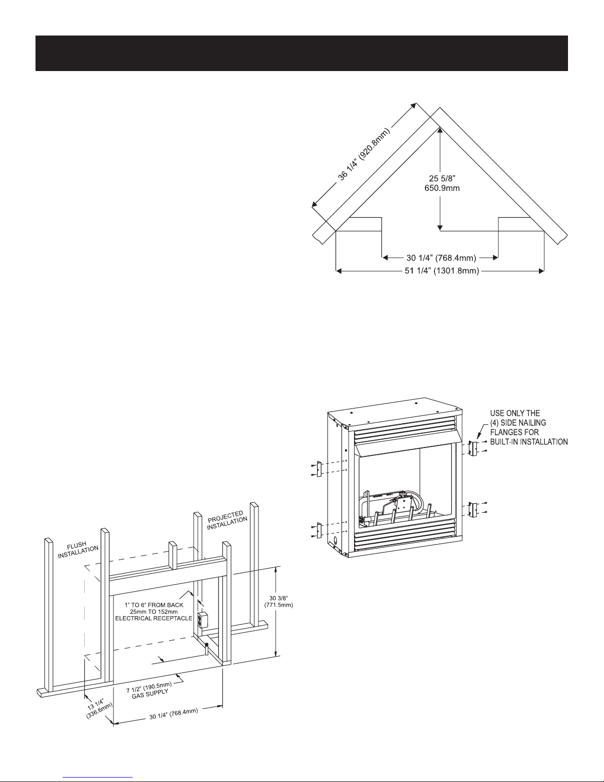
BUILT-IN FIREPLACE INSTALLATION
Built-In Fireplace Installation
Built-in installation of this replace involves installing the replace
into a framed-in enclosure. This makes the front of the replace
ush with a wall. If installing a mantel above the replace, you
must follow the clearances shown in Figure 9. Follow the instruc-
tions below to install the replace in this manner.
Frame in rough opening. Use dimensions show in Figure 1 for a
conventional rough opening. Use dimensions shown in Figure 2
for corner rough opening. Be sure to provide gas line for replace
and electrical power for optional blower assembly.
1. Attach two nailing anges to rebox sides with two 10 x 1/2"
screws for each nailing ange.
2. Gas line connections must be made at this time. When facing
the appliance, the gas supply will enter on the right-hand side.
See "Gas Supply" page 11.
3. Insert replace into enclosure.
4. Attach nailing anges to framing with a screw or nail.
5. Finished wall surface will be ush to the leading edge of re-
place top and sides.
6. Installation of built-in replace is completed.
Rough Opening for Installing in Corner
Figure 2
Rough Opening for Installing in Wall
Figure 1
Figure 3
30816-7-0814Page 6
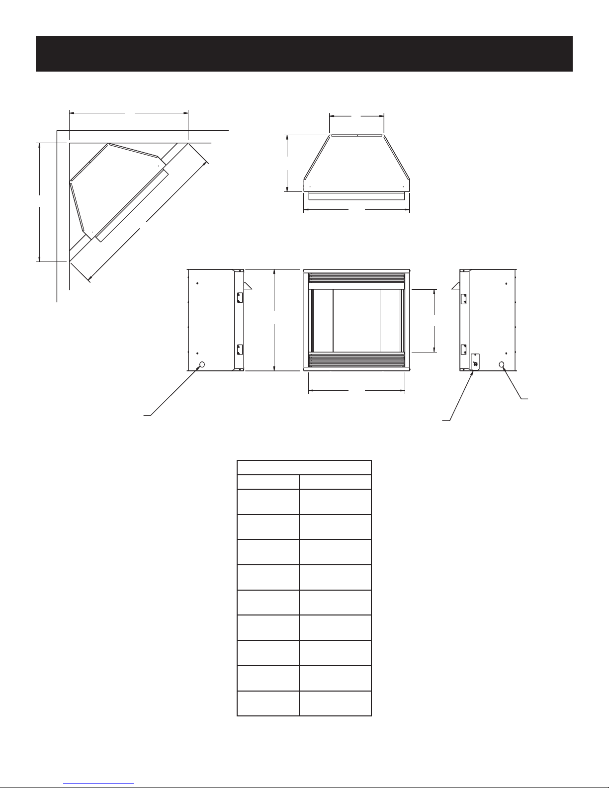
FIREPLACE DIMENSIONS
LINE
OPENING
J
C
I
K
A
G
B
D
E
GAS
GAS LINE
OPENING
VFD26 Series Dimensions
Index Letter Dimension
A
B
C
D
E
G
I
J
K
Figure 4
30 1/4"
768mm
30"
762mm
13 1/8"
333mm
18 1/8"
460mm
26"
660mm
25"
635mm
36 1/4"
921mm
36 1/4"
921mm
51 1/4"
1302mm
JUNCTION BOX
ASSEMBLY
30816-7-0814 Page 7
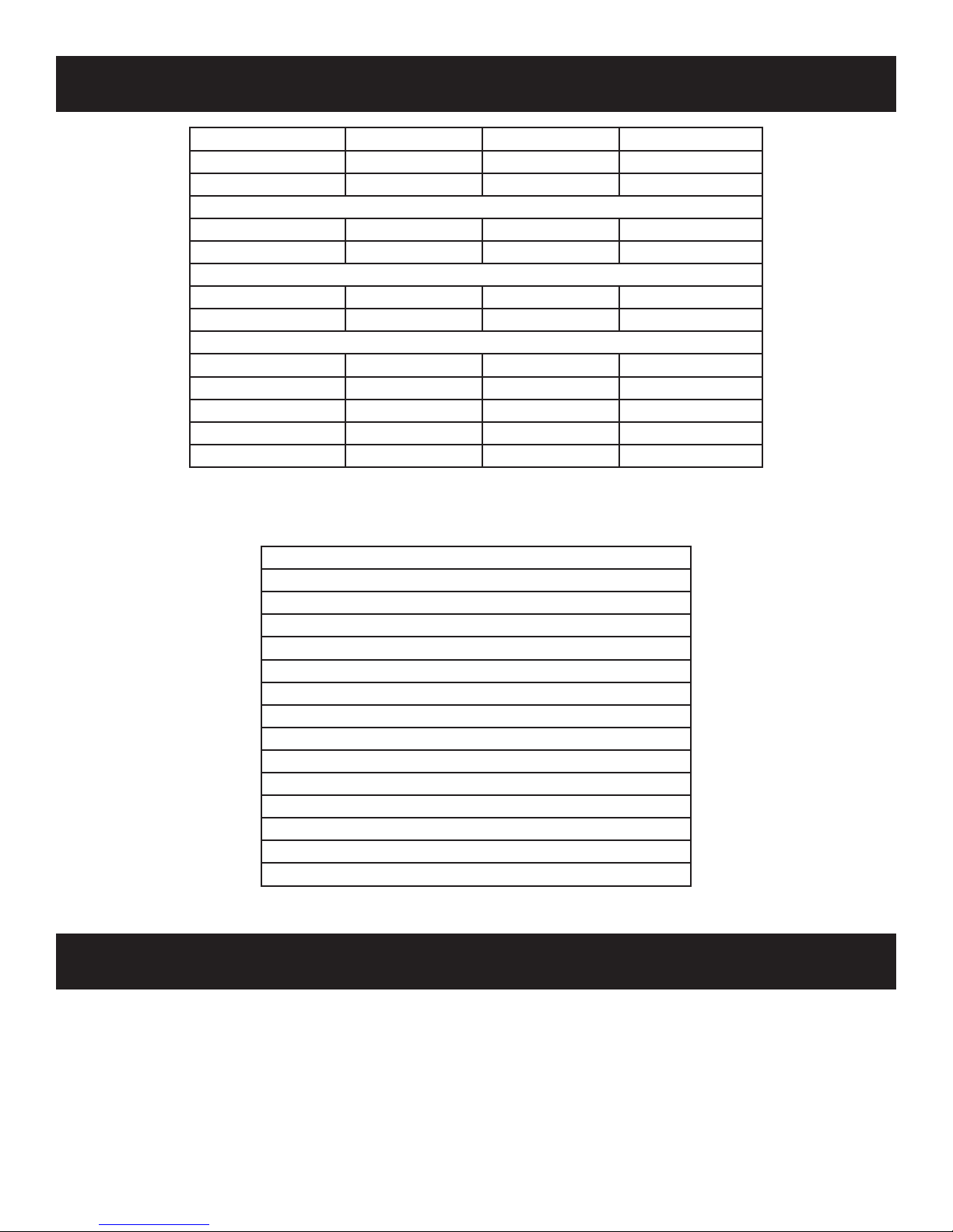
SPECIFICATIONS
Model VFD26F(M,P)(3,7) VFD26F(M,P)2 VFD26FP(3,7)0L10
Input Maximum 20,000 20,000 10,000
Minimum 14,000 14,000 N/A
NAT
Orice 2.10 mm (P-288) #49 (.073") P-265 #53 (.0595") P-214
Air Shutter Opening 1/8" 1/8" 1/8"
LP
Orice #55 (.052") P-182 #55 (.052") P-182 #64 (.036") P-193
Air Shutter Opening 1/4" 1/4" 1/4"
Fireplace Dimensions
Height 30 1/4" 30 1/4" 30 1/4"
Depth 13 1/8" 13 1/8" 13 1/8"
Front Width 30" 30" 30"
Rear Width 25" 25" 25"
Gas Inlet 3/8" 3/8" 3/8"
Accessories
FBBX Blower Extension Kit (MUST order FBB4)
FBB4 Automatic Blower (MUST order FBBX)
VPS26HP Bottom Trim Kit
VF2H26HP Hammered Pewter Hood Kit
VPF26HP Hammered Pewter Trim Kit
FPP26E Brick Liner
VPL26HP Hammered Pewter Slat Louver
Accessories for Millivolt VFD26F(M,P)(3,7) Only
FRBC Battery Operated Remote Control
FRBTC Battery Operated Remote Control w/Thermostat
FREC Electric Remote Control
FWS-1 Wall Switch
TMV Wall Thermostat, Millivolt - Reed Switch
TRW Wireless Remote Wall Thermostat
WATER VAPOR: A BY-PRODUCT OF UNVENTED ROOM HEATERS
Water vapor is a by-product of gas combustion. An unvented room
heater produces approximately one ounce (30ml) of water for every
1,000 BTU's (.3KW's) of gas input per hour. .
Unvented room heaters are recommended as supplemental heat (a
room) rather than a primary heat source (an entire house). In most
supplemental heat applications, the water vapor does not create a
problem. In most applications, the water vapor enhances the low
humidity atmosphere experienced during cold weather.
The following steps will help insure that water vapor does not
become a problem.
1. Be sure the heater is sized properly for the application, including
ample combustion air and circulation air.
2. If high humidity is experienced, a dehumidier may be used to
help lower the water vapor content of the air.
3. Do not use an unvented room heater as the primary heat source.
30816-7-0814Page 8
PROVISIONS FOR ADEQUATE COMBUSTION & VENTILATION AIR
This heater shall not be installed in a conned space or unusually tight construction unless provisions are provided for adequate
combustion and ventilation air.
A conned space is an area with volume less than 50 cubic feet per
1,000 Btuh of the combined input rates of all appliances drawing
combustion air from that space. Small areas such as equipment
rooms are conned spaces. Furnaces installed in a conned space
which supply heated air to areas outside the space must draw return
air from outside the space through tightly sealed return air ducts. A
conned space must have 2 openings into the space for combustion air. One opening must be within 12 inches of the ceiling and
the other must be within 12 inches of the oor. The required sizing
of these openings is determined by whether inside or outside air is
used to support combustion, the method by which the air is brought
to the space (vertical or horizontal duct) and by the total input rate
of all appliances in the space.
Unusually Tight Construction
The air that leaks around doors and windows may provide enough
fresh air for combustion and ventilation. However, in buildings of
unusually tight construction, you must provide additional fresh air.
Unusually tight construction is dened as construction
where:
a. Walls and ceilings exposed to the outside atmosphere have
a continuous water vapor retarder with a rating of one perm
or less with openings gasketed or sealed, and
b. Weatherstripping has been added on openable windows and
doors, and
c. Caulking or sealants are applied to areas such as joints
around window and door frames, between sole plates and
oors, between wall-ceiling joints, between wall panels, at
penetrations for plumbing, electrical, and gas lines, and at
other openings.
If your home meets all of the three criteria above, you must provide
additional fresh air. See “Ventilation Air From Outdoors,” page
10.
Determining if You Have a Conned or Unconned Space
Use this worksheet to determine if you have a conned or unconned
space.
Space: Includes the room in which you will install heater plus any
adjoining rooms with doorless passageways or ventilation grills
between the rooms.
1. Determine the volume of the space (length x width x height).
Length x Width x Height = cu. ft. (volume of
space)
Example: Space size 16 ft. (length) x 10 ft. (width) x 8 ft. (ceiling
height) = 1,280 cu. ft. (volume of space)
If additional ventilation to adjoining room is supplied with grills
or openings, add the volume of these rooms to the total volume
of the space.
2. Divide the space volume by 50 cubic feet to determine the
maximum BTU/Hr the space can support.
(volume of space) ÷ 50 cu. ft. = (maximum
BTU/Hr the space can support)
Example: 1,280 cu. ft. (volume of space) ÷ 50 cu. ft. = 25.6 or
25,600 (maximum BTU/Hr the space can support)
3. Add the BTU/Hr of all fuel burning appliances in the space.
Vent-free heater BTU/Hr
Gas water heater BTU/Hr
Gas furnace BTU/Hr
Vented gas heater BTU/Hr
Gas replace logs BTU/Hr
Other gas appliances* + BTU/Hr
Total = BTU/Hr
Example: Vented gas heater 20,000 BTU/Hr
Vent-free heater + 18,000 BTU/Hr
Total = 38,000 BTU/Hr
*Do not include direct-vent gas appliances. Direct vent draws
combustion air from the outdoors and vents to the outdoors.
4. Compare the maximum BTU/Hr the space can support with the
actual amount of BTU/Hr used.
BTU/Hr (maximum the space can support)
BTU/Hr (actual amount of BTU/Hr used)
Example:
25,600 BTU/Hr (maximum the space can support)
38,000 BTU/Hr (actual amount of BTU/Hr used)
WARNING
If the area in which the heater may be operated is smaller than that
dened as an unconned space or if the building is of unusually
tight construction, provide adequate combustion and ventilation
air by one of the methods described in the National Fuel Gas
Code, ANSI Z223.1/NFPA 54, Air for Combustion and Ventilation,
or applicable local codes.
The space in the above example is a conned space because the
actual BTU/Hr used is more than the maximum BTU/HR the space
can support. You must provide additional fresh air. Your options
are as follows:
A. Rework worksheet, adding the space of an adjoining room. If
the extra space provides an unconned space, remove door
to adjoining room or add ventilation grills between rooms. See
Ventilation Air From Inside Building.
B. Vent room directly to the outdoors. See Ventilation Air From
Outdoors.
C. Install a lower BTU/Hr heater, if lower BTU/Hr size makes room
unconned.
If the actual BTU/Hr used is less than the maximum BTU/Hr the
space can support, the space is an unconned space. You will need
no additional fresh air ventilation.
WARNING
You must provide additional ventilation air in a conned
space.
30816-7-0814 Page 9
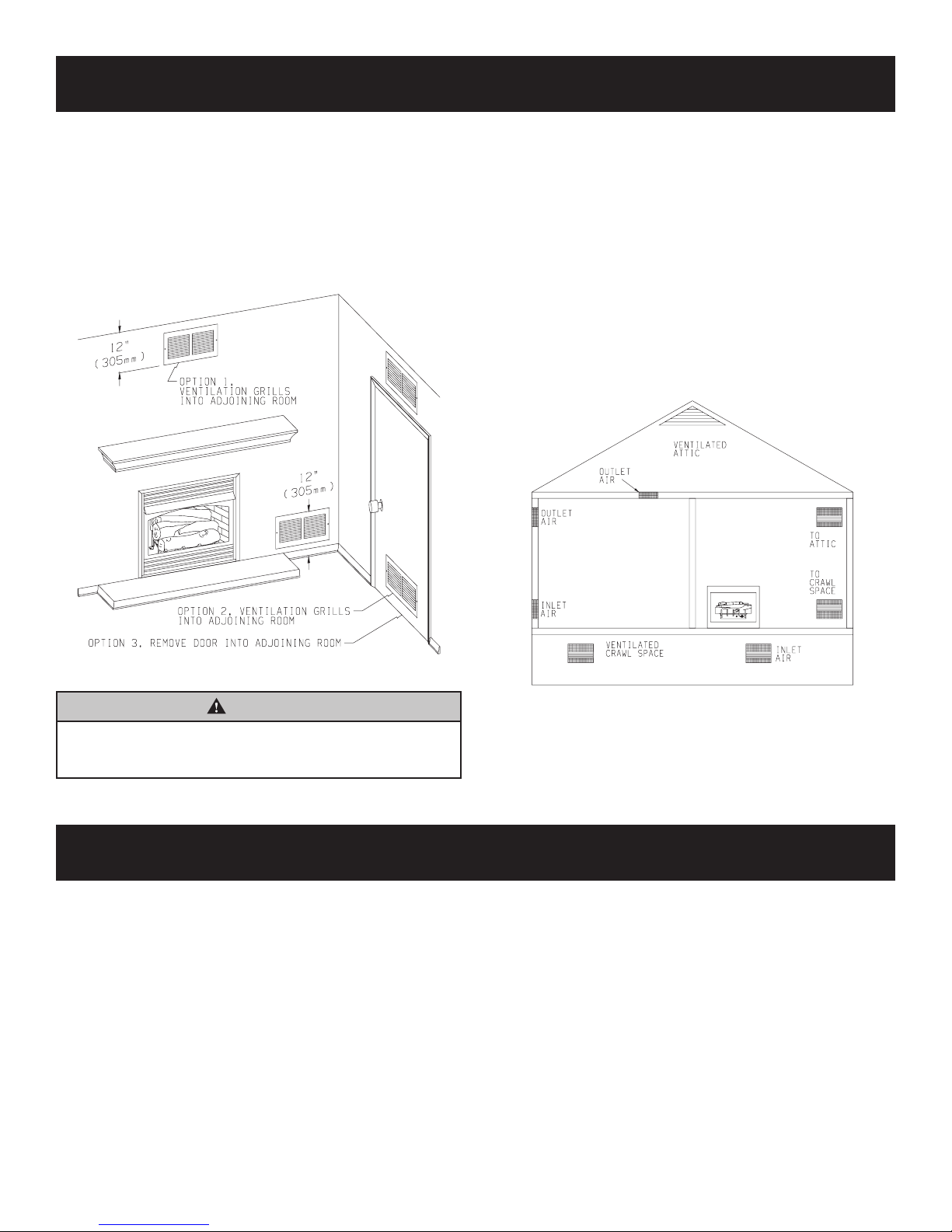
PROVISIONS FOR ADEQUATE COMBUSTION & VENTILATION AIR
VENTILATION AIR
Ventilation Air From Inside Building
This fresh air would come from an adjoining unconned space. When
ventilating to an adjoining unconned space, you must provide two
permanent openings: one within 12" of the ceiling and one within
12" of the oor on the wall connecting the two spaces (see options
1 and 2, Figure 5). You can also remove door into adjoining room
(see option 3, Figure 5). Each ventilation grill or opening shall have
a minimum free area of one square inch per 1,000 BTU/HR of the
total input rating of the gas equipment in the conned space.
Ventilation Air From Outdoors
Provide extra fresh air by using ventilation grills or ducts. You must
provide two permanent openings: one within 12" of the ceiling and
one with 12" of the oor. Connect these items directly to the outdoors
or spaces open to the outdoors. These spaces include attics and
crawl spaces. In most cases for direct communication with the
outdoors or direct communication through a vertical duct a free
area opening of one square inch per 4,000 BTU/HR of heater input
rating for each grill. If a horizontal duct is used, a grill free area or
duct opening shall have a free area opening of one square inch per
2,000 BTU/HR for each grill. Follow the National Fuel Code, ANSI
Z223.1/NFPA 54, Air for Combustion and Ventilation, or applicable
local codes, for required size of ventilation grills or ducts.
IMPORTANT: Do not provide openings for inlet or outlet air into attic
if attic has a thermostat-controlled power vent. Heated air entering
the attic will activate the power vent.
Figure 5
WARNING
Rework worksheet, adding the space of the adjoining
unconned space. The combined spaces must have enough
fresh air to supply all appliances in both spaces.
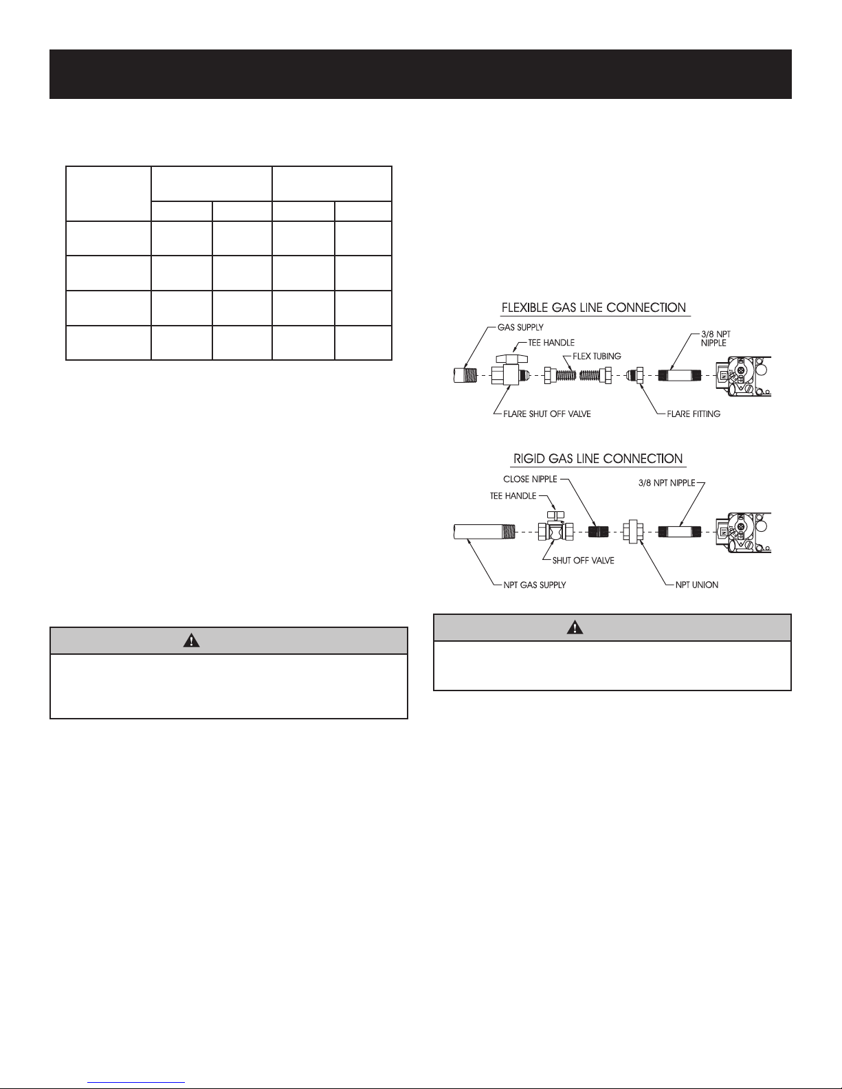
CONNECTING THE GAS
The inlet connection is located on the right side of the gas valve.
Attach gas inlet line to gas valve.
If installing the an Optional Blower, it must be installed before
connecting the gas line.
Figure 6
30816-7-0814Page 10
GAS SUPPLY
Check all local codes for requirements, especially for the size and
type of gas supply line required.
Recommended Gas Pipe Diameter
Schedule 40 Pipe
Pipe Length
0-10 feet
0-3 meters
10-40 feet
4-12 meters
40-100 feet
13-30 meters
100-150 feet
31-46 meters
NOTICE: Never use plastic pipe. Check to conrm whether your
local codes allow copper tubing or galvanized.
NOTICE: Since some municipalities have additional local codes, it is
always best to consult your local authority and installation code.
Installing a New Main Gas Cock
Each appliance should have its own manual gas cock.
A manual main gas cock should be located in the vicinity of the unit.
Where none exists, or where its size or location is not adequate,
contact your local authorized installer for installation or relocation.
Compounds used on threaded joints of gas piping shall be resistant
to the action of liqueed petroleum gases. The gas lines must be
checked for leaks by the installer. This should be done with a soap
solution watching for bubbles on all exposed connections, and if
unexposed, a pressure test should be made.
Inside Diameter
Nat. L.P. Nat. L.P.
1/2”
12.7mm
1/2”
12.7mm
1/2”
12.7mm
3/4”
19mm
3/8”
9.5mm
1/2”
12.7mm
1/2”
12.7mm
1/2”
12.7mm
12.7mm
15.9mm
22.2mm
WARNING
Never use an exposed ame to check for leaks. Appliance
must be disconnected from piping at inlet of control valve and
pipe capped or plugged for pressure test. Never pressure test
with appliance connected; control valve will sustain damage!
A gas valve and ground joint union should be installed in the gas
line upstream of the gas control to aid in servicing. It is required by
the National Fuel Gas Code that a drip line be installed near the gas
inlet. This should consist of a vertical length of pipe tee connected
into the gas line that is capped on the bottom in which condensation
and foreign particles may collect.
The use of the following gas connectors is recommended:
— ANS Z21.24 Appliance Connectors of Corrugated Metal Tubing
and Fittings
— ANS Z21.45 Assembled Flexible Appliance Connectors of Other
Than All-Metal Construction
The above connectors may be used if acceptable by the authority
having jurisdiction. The state of Massachusetts requires that a exible appliance connector cannot exceed three feet in length.
30816-7-0814 Page 11
Tubing, Type L
Outside Diameter
1/2”
5/8”
3/4”
19mm
7/8”
3/8”
9.5mm
1/2”
12.7mm
1/2”
12.7mm
3/4”
19mm
Pressure Testing of the Gas Supply System
1. To check the inlet pressure to the gas valve, a 1/8" (3mm) N.P.T.
plugged tapping, accessible for test gauge connection, must
be placed immediately upstream of the gas supply connection
to the appliance.
2. The appliance and its individual shutoff valve must be
disconnected from the gas supply piping system during any
pressure testing of that system at test pressures in excess of
1/2 psig (3.5 kPa).
3. The appliance must be isolated from the gas supply piping
system by closing its individual manual shutoff valve during
any pressure testing of the gas supply piping system at test
pressures equal to or less than 1/2 psig (3.5 kPa).
Figure 7
WARNING
If one of the above procedures results in pressures in excess of
1/2 psig (14" w.c.) (3.5 kPa) on the appliance gas valve, it will
result in a hazardous condition.
Checking Manifold Pressure
3 Series Millivolt Natural gas will have a manifold pressure of
approximately 3.5" w.c. (.871kPa) for maximum input or 1.7" w.c.
(.423kPa) for minimum input at the pressure regulator outlet with
the inlet pressure to the pressure regulator from a minimum of 5.0"
w.c. (1.120kPa) for the purpose of input adjustment to a maximum
of 10.5" w.c. (2.614kPa).
2 Series Hydraulic Thermostat Natural gas will have a manifold
pressure of approximately 6.0" w.c. (1.49kPa) at the pressure
regulator outlet with the inlet pressure to the pressure regulator
from a minimum of 7.0" w.c. (1.74kPa) for the purpose of input
adjustment to a maximum of 10.5" w.c. (2.615kPa).
3 Series Millivolt Propane gas will have a manifold pressure
approximately 10.0"w.c. (2.49kPa) for maximum input or
6.3"w.c. (1.568kPa) for minimum input at the pressure regulator
outlet with the inlet pressure to the pressure regulator from
a minimum of 11.0"w.c. (2.739kPa) for the purpose of input
adjustment to a maximum of 13.0"w.c. (3.237kPa).
2 Series Hydraulic Thermostat Propane gas will have a manifold
pressure approximately 10.0"w.c. (2.49kPa) at the pressure regulator
outlet with the inlet pressure to the pressure regulator from a minimum
of 11.0"w.c. (2.739kPa) for the purpose of input adjustment to a
maximum of 13.0"w.c. (3.237kPa).
36”
(91.44 cm)
2” (5.08 cm)
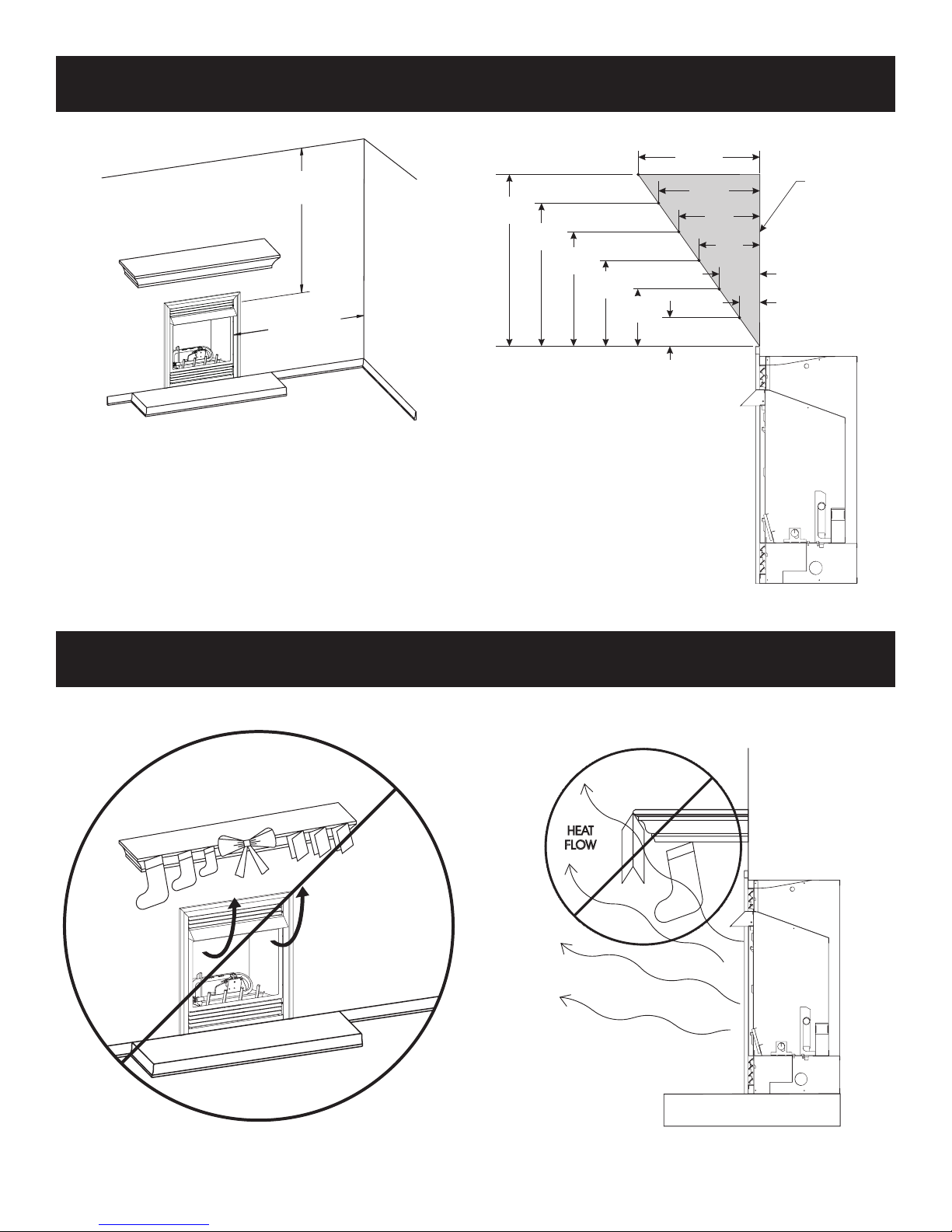
CLEARANCES
COMBUSTIBLES
12”
(27.9cm)
Minimum Wall and Ceiling Clearances
Figure 8
This replace can be installed with zero (0") clearance to
combustible material.
When facing the front of the appliance the minimum clearances to
combustible construction (material) are the following:
1. Clearances from the right side or left side of the replace opening
to any combustible wall or material should not be less than 2
inches.
2. Clearances from the top of the replace opening to the ceiling
should not be less than 36 inches.
Mantel Clearances for Built-in Installation
(30.5cm)
4 3/4”
(12.1cm)
10”
(25.4cm)
(20.3cm)
(15.2cm)
8”
6”
0
11”
10 1/4”
(26.0cm)
TOPOF FRAME
MANTEL
9½”
(24.1cm)
8 3/4”
(22.2cm)
5½”
(14.0cm)
Figure 9
4”
(10.2cm)
2½”
(63.0cm)
ALLOWED
COMBUSTIBLE MATERIAL
Do not attach combustible material to the mantel of your replace.
This is a re hazard.
HEAT
FLOW
No greeting cards, stockings or ornamentation of any type should be
placed on or attached to the replace. This is a heating appliance.
The ow of heat can ignite combustibles.
Figure 10
Figure 11
30816-7-0814Page 12
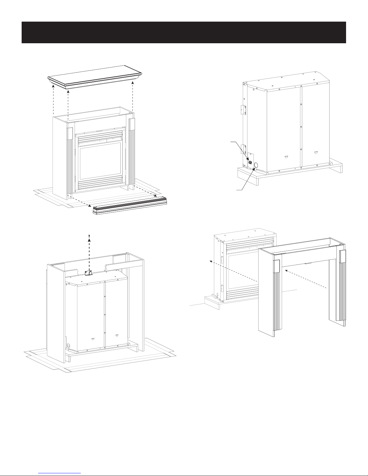
INSTALLATION OF FIREPLACE AND MANTEL
1. Remove replace from carton.
2. Remove mantel top and front base from mantel assembly.
3. Remove screw attached to replace top and through
"L Bracket" attached to back of breast board.
6. Place back base and replace in desired location.
7. Connect gas line and electrical wiring at this time in accordance with local codes.
ELECTRICAL
CONNECTION
OPENING
GAS LINE
CONNECTION
OPENING
8. Place mantel assembly around replace and center. Replace
the screw removed in step 3 to secure replace to mantel
assembly.
4. Remove mantel assembly from replace.
5. Remove shrink wrap and logs from replace.
30816-7-0814 Page 13
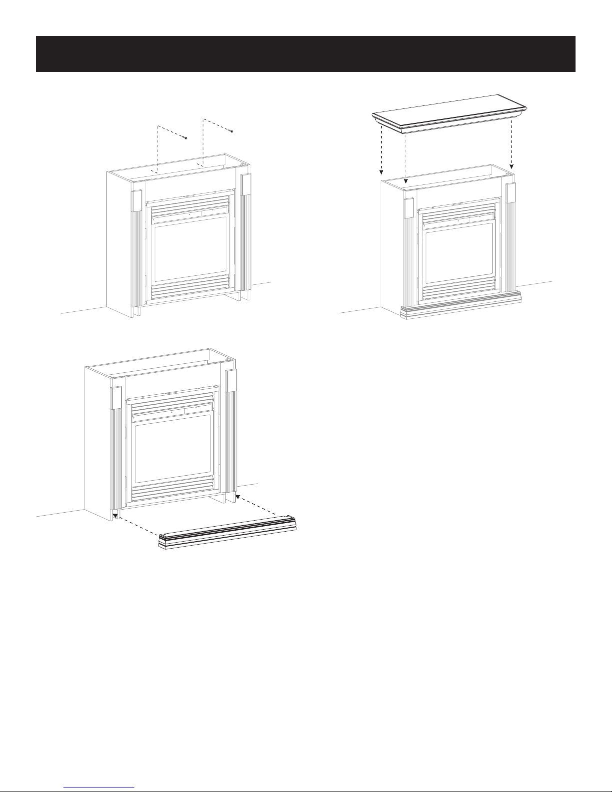
INSTALLATION OF FIREPLACE AND MANTEL
9. Attach mantel assembly to studs in the wall through the
"back brace" using two 3" drywall screws provided.
10. Slide front base under front of mantel assembly.
11. Place mantel top onto mantel assembly.
12. Install outer trim. See Page 15.
13. Install ber logs per the Log Placement Instructions. See
Page 16.
14. Install hood. See Page 15.
30816-7-0814Page 14
 Loading...