

Empire Comfort Systems LS48THF-1 Installation Instructions And Owner's Manual
INSTALLATION INSTRUCTIONS
OWNER’S MANUAL
LS48THF-1
LOGS AND ROCKS SET
This decorative media set includes an unusual
assortment of logs and rocks in varying textures
and colors to complement your linear replace plus stainless steel coils to add a unique air.
For ease of installation, unpack all pieces and lay
out so that any identifying letters are visible.
WARNINGS
If the information in this manual is not followed
exactly, a re or explosion may result causing
property damage, personal injury or loss of life.
– Do not store or use gasoline or other ammable
vapors and liquids in the vicinity of this or any
other appliance.
– Installation and service must be performed by
a qualied installer, service agency or the gas
supplier.
WHAT TO DO IF YOU SMELL GAS
• Do not try to light any appliance.
• Do not touch any electrical switch; do not use
any phone in your building.
• Immediately call your gas supplier from
neighbor’s phone. Follow the gas supplier’s
instructions.
• If you cannot reach your gas supplier, call the
re department.
AND
LOG SET FOR USE WITH
DIRECT VENT FIREPLACE
MODELS:
DVLL48BP92(N,P)-1
GAS-FIRED
INSTALLER: Leave this manual with the appliance.
CONSUMER: Retain this manual for future
reference.
WARNING: If not installed, operated and maintained
in accordance with the manufacturer's instructions,
this product could expose you to substances in fuel
or from fuel combustion which can cause death or
serious illness.
Page 1
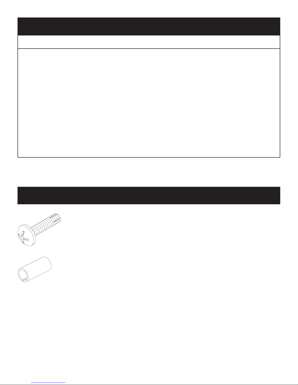
TABLE OF CONTENTS
PH PN HD SCREW
SECTION PAGE
Important Installation Guidelines ..............................................................................3
General Information .................................................................................................3
Rock Identication ....................................................................................................4
Log Identication ......................................................................................................5
Rock and Log Placement ..................................................................................6 - 22
Master Parts Distributor List ...................................................................................23
How To Order Repair Parts ....................................................................................23
HARDWARE PACK
R12061 (QUANTITY 12)
8-32 X 3/4”
R8234 (QUANTITY 12)
1/4” OD X 9/16”SPACER
Note: For the LS48THF Logs and Rock set, only (8) each of the above screws and spacers will be
used.
36474-0-0316Page 2

IMPORTANT INSTALLATION GUIDELINES
Before You Begin
It is recommended that prior to installing the LS48THF Logs and
Rock Kit, test re the replace to make sure it is operational.
Proper Log Placement
Log placement is critical to proper burner performance. Logs
must be correctly positioned. The photos in this manual show
the proper pinned position for logs and rocks on this set. Owners
need to be shown proper log and rock placement and instructed
not to move the logs and rocks.
Logs and rocks must t rmly onto the locating pins when
positioned as shown in the photos. Malformed logs, rocks, or logs
with sloppy pin holes must be replaced.
Proper Placement of Crushed Glass Media
This replace is designed to use one layer deep of crushed glass
media on the burner. The maximum amount of crushed glass
media on the burner screen should not exceed 2-1/2 lbs. An
additional 5 lbs. of crushed glass media maybe spread out over
the burner cover and accent light glass panels.
It is recommended that prior to placing the rocks and logs, add
the single layer of crushed glass on the burner screen after only.
Then the remainder of crushed glass media be added after the
log and rock set has been properly installed.
CAUTION: Do not place crushed glass around the pilot
assembly. Crushed glass must be placed on the burner screen
in a single layer. Additional crushed glass may be placed on
the barrier cover areas away from the barrier screen. See
complete installation section on page 22.
Make Owners Aware of Proper Log Set Operation
Properly installed and properly maintained log sets do not deposit
soot on the logs. If users see soot appear on a log, call for
service. Do not continue to operate the replace.
GENERAL INFORMATION
Qualied Installing Agency
Installation and replacement of gas piping, gas utilization
equipment or accessories and repair and servicing of
equipment shall be performed only by a qualied agency.
The term "qualied agency" means any individual, rm,
corporation, or company that either in person or through
a representative is engaged in and is responsible for (a)
the installation, testing, or replacement of gas piping or
(b) the connection, installation, testing, repair, or servicing
of equipment; that is experienced in such work; that
is familiar with all precautions required, and that has
complied with all the requirements of the authority having
jurisdiction.
The installation must conform with local codes or, in the
absence of local codes, with the National Fuel Gas Code,
ANSI Z223.1/NFPA54.*
*Available from the American National Standards Institute, Inc. 11 West
42nd St., New York, N.Y. 10018.
State of Massachusetts: The installation must be made
by a licensed plumber or gas tter in the Commonwealth
of Massachusetts.
Sellers of unvented propane or natural gas-red supplemental room heaters shall provide to each purchaser a
copy of 527 CMR 30 upon sale of the unit.
Appliance Certication
This logset is design certied in accordance with American
National Standard/CSA Standard ANSI Z21.88/CSA 2.33 and
by Underwriters Laboratories for use with a Direct Vent Gas
Fireplace Heater and shall be installed according to these
instructions.
36474-0-0316 Page 3
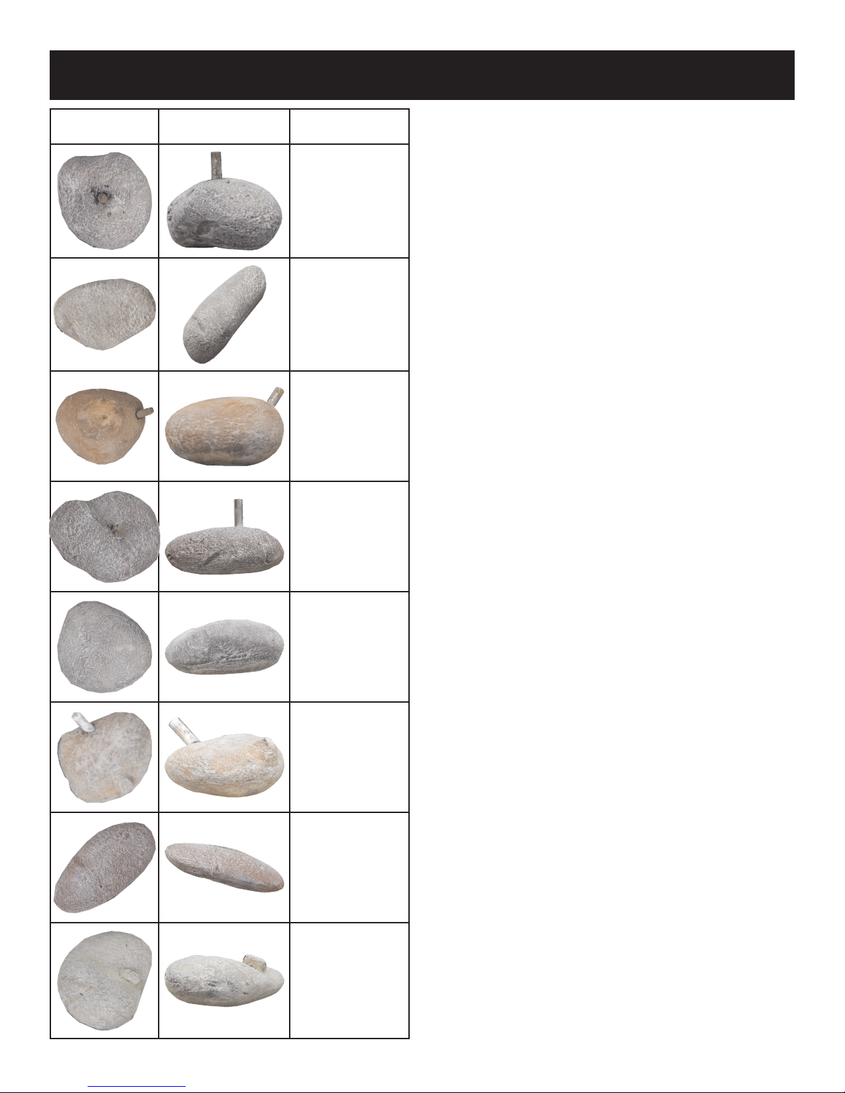
ROCK IDENTIFICATION
TOP VIEW FRONT VIEW
DESCRIPTION &
PART NUMBER
Rock A
35777
Rock B
35778
Rock E
35781
Rock F
35782
Rock G
35783
Rock H
35784
Rock I
35785
Rock J
35786
36474-0-0316Page 4
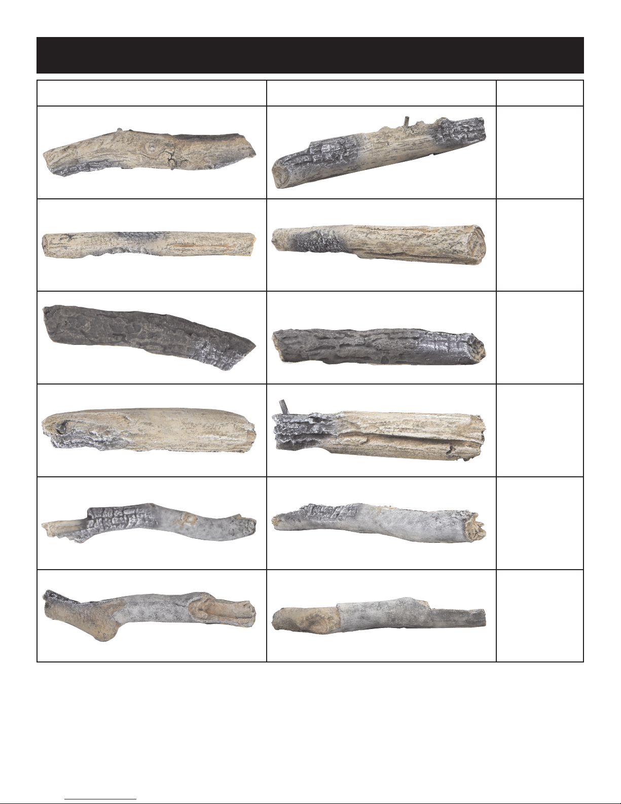
LOG IDENTIFICATION
TOP VIEW FRONT VIEW
DESCRIPTION &
PART NUMBER
Log L
35788
Log M
35789
Log N
35790
Log O
35791
Log P
35792
Log Q
35793
36474-0-0316 Page 5

ROCK AND LOG PLACEMENT
P
Tools Needed:
Protective Gloves
Phillips Screw Driver or Power Drill with Phillips Drive
Before you begin: Do not, handle these logs with your bare
hands! Always wear gloves to prevent skin irritation. After
handling logs, wash your hands gently with soap and water.
All Logs
The positioning of the logs is critical to the safe and clean
operation of this heater. Sooting and other problems may result if
the logs are not properly and rmly positioned in the appliance.
Refer to Figure 1 for the following warning.
Warning: Failure to position the parts in accordance with this
diagram or failure to use only parts specically approved with
this appliance may result in property damage or personal injury.
Attention: Refer to Pages 4 and 5 Parts List and Parts View to
order logs or rocks.
NOTE: Once the installation is complete with the logs, rocks,
and crushed glass media in place, operate the replace to verify
ame appearance. If there are ames directly impinging a log,
turn off replace, then remove the crushed glass media directly
below where the ame impingement occurred. This should
eliminate sooting on the log, and provide a more pleasing ame
appearance.
Installation of the Pins for Log and Rock Placement
The LS48THF Log and Rock Hardware kit includes twelve
8-32x3/4" long self-threading screws, and twelve 9/16" long
spacers. For this log and rock set, only eight screws and spacers
are needed. Install the screws and spacers prior to the log and
rock placement.
Note: It is highly recommended that the replace liner be installed
prior to installing the log and rock spacers so interference with
the locator pins is avoided.
Use a power drill with a Phillips drive to install the screws through
a spacer at each of the eight pilot hole locations provided in the
burner cover. See Figure 1. These will be the locator pins for the
logs and rocks.
Note: If the replace includes the accent light glass panels,
please remove the glass panels prior to installing the Logs and
Rock screws and spacers. Replace the glass panels after the
spacers are installed.
Q
L
F
N
M
B
A
E
J
Rock and Log Placement - Figure 1
O
I
G
H
36474-0-0316Page 6
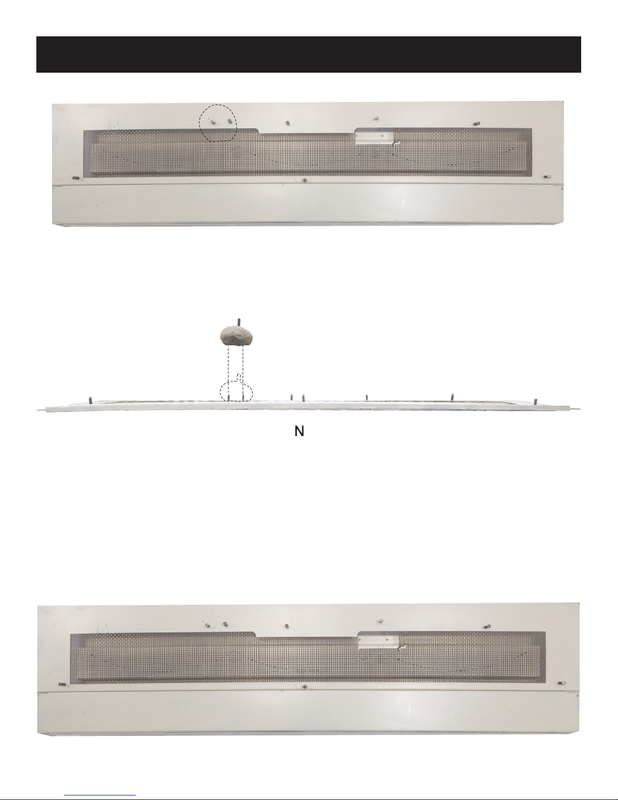
ROCK AND LOG PLACEMENT
1. Place Rock A onto Burner Pins 1 and 2.
TOP VIEW
FRONT VIEW
1
2
3
4
6
7
5
8
36474-0-0316 Page 7
Burner Pin Locations
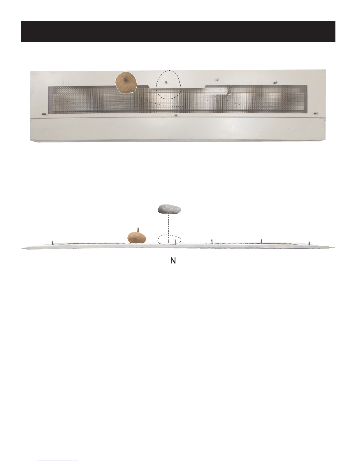
2. Place Rock J onto Burner Pin 3.
ROCK AND LOG PLACEMENT
TOP VIEW
FRONT VIEW
36474-0-0316Page 8
 Loading...