

Empire Comfort Systems LS-18FAO-1, LS-18FAC-1, LS-24FAO-1, LS-18FAS-1, LS-30FAC-1 User Manual
...Page 1
INSTALLATION INSTRUCTIONS
AND OWNER'S MANUAL
The White Mountain Log Collection
LOG SET FOR UNVENTED
GAS LOG HEATER
OR
VENTED DECORATIVE APPLIANCE
MODELS
WARNINGS
If the information in this manual is not followed
exactly, a fire or explosion may result causing
property damage, personal injury or loss of life.
– Do not store or use gasoline or other flam-
mable
this or any other appliance.
vapors and liquids in the vicinity of
LS-18FAC-1
LS-24FAC-1
LS-30FAC-1
LS-18FAO-1
LS-24FAO-1
LS-30FAO-1
LS-18FAS-1
LS-24FAS-1
LS-30FAS-1
EFFECTIVE DATE
SEPTEMBER, 2003
Installer: Please leave these instructions
with the consumer.
Consumer: Please retain these instructions
for future use.
WHAT TO DO IF YOU SMELL GAS
• Do not try to light any appliance.
• Do not touch any electrical switch; do not
use any phone in your building.
• Immediately call your gas supplier from
neighbor’s phone. Follow the gas supplier’s
instructions.
• If you cannot reach your gas supplier, call
the fire department.
– Installation and service must be performed
by a qualified installer , service agency or the
gas supplier.
Log sets comply with ANSI Z21.11.2 Unvented
Heaters and also comply with ANSI Z21.60
Decorative Vented Appliances for Solid Fuel
Burning Fireplaces. State or local codes may only
allow operation of log sets in a vented
configuration. Check your state or local codes.
WARNING: If not installed, operated and maintained in accordance with the manufacturer's
instructions, this product could expose you to
substances in fuel or from fuel combustion which
can cause death or serious illness.
Page 115997-0-0903
Page 2

TABLE OF CONTENTS
Section Page
Important Installation Guidelines................................................................................................................... 3
General Information ....................................................................................................................................... 3
Log Placement................................................................................................................................................ 4
LS-18FA(C,O,S)-1 Photos ............................................................................................................................. 5
LS-24FA(C,O,S)-1 Photos ............................................................................................................................. 6
LS-30FA(C,O,S)-1 Photos ............................................................................................................................. 7
Parts List & Parts View .................................................................................................................................. 8
How to Order Repair Parts ............................................................................................................................. 8
Page 2 15997-0-0903
Page 3

IMPORTANT INSTALLATION GUIDELINES
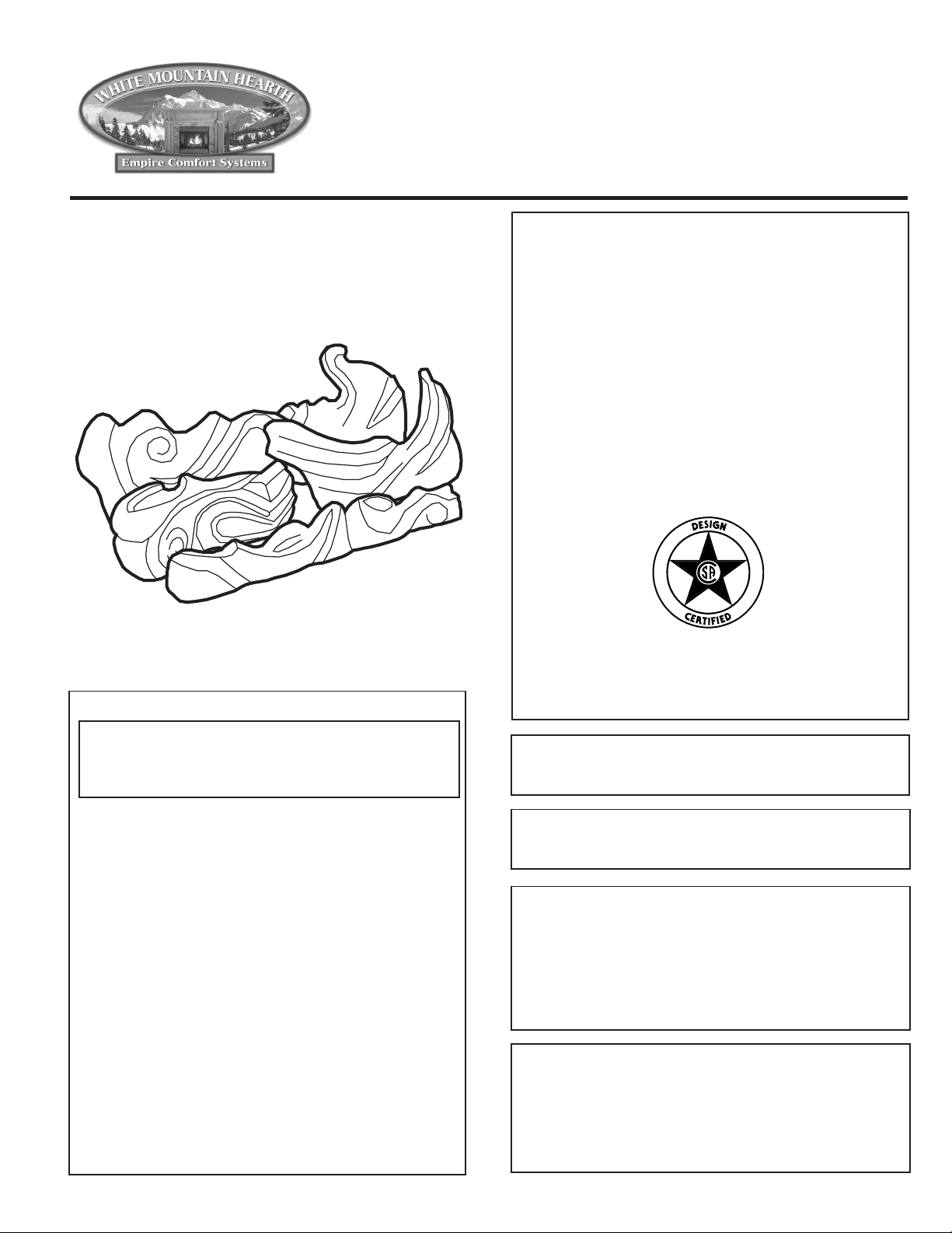
Proper Log Placement
Log placement is critical to proper burner performance. Logs
must be correctly positioned onto the burner. The photos in this
manual show the proper pinned position for logs on this set.
Owners need to be shown proper log placement and instructed not
to move the logs.
Logs must fit firmly onto the burner when positioned as shown in
the photos. Misformed logs or logs with sloppy pin holes must be
replaced.
Proper Placement of Rock Wool and Decorative Lava Rock
Rock wool can be added to burners for a glowing ember effect. It
must be positioned only on the front portion of the burner. The
photos in this manual show the proper placement of rock wool.
Decorative lava rock or small wood pieces should never be placed
on the burner. These items are only for placement on the floor of
the fireplace or firebox.
Proper Primary Airflow into Burner
For proper burner operation and flame appearance, the flow of
primary air into the venturi tube, located on the rear of the burner,
must not be reduced. This flow of air is reduced if dirt, lint or other
obstructions build-up around or inside the venturi. Any obstruction
in the venturi tube area must be removed. The flow of air into the
venturi is also reduced if the gas orifice isn’t centered in the
venturi inlet and/or is not aligned with the venturi. Any
misalignment of the burner orifice may be corrected by bending
the shutter cap holding the orifice to the inlet of the venturi tube.
Ceiling Fans, Portable Fans or Logs Installed Near Cold Air
Returns
Ceiling fans or oscillating floor type fans need to be monitored
during the operation of vent-free logs. If the air blows directly into
the flame causing it to impinge on the log set, or firebox, it should
be turned off or redirected. Ceiling fans could be reversed to
possibly eliminate flame impingement, and the floor fan could be
redirected. Upon installation, be aware of any cold air returns or
vents in the proximity of the log set. Any draft created around a
vent-free log set can cause the flame to impinge on the log and
create a sooting situation.
WARNING: Do not allow fans to blow directly into the fireplace.
Avoid any drafts that alter burner flame patterns.
WARNING: Do not use a blower insert, heat exchanger insert or
other accessory not approved for use with this heater.
Candles
Avoid the use of scented or decorative candles while the log set
is in operation. Candles produce a residue in the air that creates
a soot like substance. Burning candles while the log set is
operating magnifies the problem. It should be noted that candles,
in general, produce soot. The amount of time burned and the
quantity of candles burned will determine the amount of soot
produced and deposited.
Make Owners Aware of Proper Log Set Operation
Properly installed and properly maintained log sets do not deposit
soot on the logs. If users see soot appear on a log, call for service.
Do not continue to operate the log set.
Sunken Fireplace
If installing this unit into a sunken fireplace, you must raise the
floor to insure adequate airflow and guard against sooting. Raise
fireplace floor using a non-combustible material, which is secure.
Glass Doors
Make sure that glass doors are open during all operations of the
logset. The opening of the glass door frame should be the
dimension used for the minimum front opening of the firebox.
Woodburning Fireplaces
The interior of the firebox and the chimney should be cleaned and
free of all creosote before installing a gas burning log set.
Creosote will soften when heated and can drop on the logset
causing odors and possibly sooting.
WARNING: Before installing in a solid-fuel burning fireplace,
the chimney flue and firebox must be cleaned of soot, creosote,
ashes and loose paint by a qualified chimney cleaner.
GENERAL INFORMATION
Qualified Installing Agency
Installation and replacement of gas piping, gas utilization equipment or accessories and repair and servicing of equipment shall be
performed only by a qualified agency. The term "qualified agency"
means any individual, firm, corporation, or company that either in
person or through a representative is engaged in and is responsible
for (a) the installation, testing, or replacement of gas piping or (b)
the connection, installation, testing, repair, or servicing of equipment; that is experienced in such work; that is familiar with all
precautions required, and that has complied with all the requirements of the authority having jurisdiction.
The installation must conform with local codes or, in the absence
of local codes, with the National Fuel Gas Code, ANSI Z223.1/
NFPA54.*
*Available from the American National Standards Institute, Inc. 11 West 42nd
St., New York, N.Y. 10018.
State of Massachusetts: The installation must be made by a
licensed plumber or gas fitter in the Commonwealth of Massachusetts.
In the Commonwealth of Massachusetts vent free products are
not approved.
State of Massachusetts requirement for installation of vented
decorative appliance in a vented fireplace is the following:
A vented decorative gas appliance must be installed in a vented
fireplace only in the state of Massachusetts. The vent damper
must be removed or welded permanently open.
Page 315997-0-0903
Page 4

LOG PLACEMENT
Before you begin: Do not, handle these logs with your bare hands! Always wear gloves to prevent skin irritation. After handling logs,
wash your hands gently with soap and water.
All Logs
The positioning of the logs is critical to the safe and clean operation of this heater. Sooting and other problems may result if the logs are
not properly and firmly positioned in the appliance.
Refer to Figure 1 for the following warning.
Warning: Failure to position the parts in accordance with this diagram or failure to use only parts specifically approved with this
appliance may result in property damage or personal injury.
PROPER INSTALLATION SEQUENCE:
LS-(18, 24, 30)FA(C,O,S) (Figure 1)
1. Place back left (#1) log onto left, rear pin on rear log support.
2. Place back right (#2) log onto right, rear pin on rear log support.
3. Place front left (#3) log onto two (2) left, front pins on burner
pan.
4. Place front right (#4) log onto two (2) right, front pins on burner
pan.
5. Place front (#5) log in front of burner pan.
6. Compare the completed log installation with the appropriate
photo from pages 5 through 7. Review previous steps to make
any necessary adjustments.
7. Log placement is completed.
Apply loose material (glowing embers) per appropriate Installation
Instructions and Owner's Manual. Replacement of loose material
(glowing embers) must be purchased from Empire Comfort
Systems, Inc. Application of excess loose material (glowing
embers) may adversely affect performance of the heater.
WARNING: All previously applied loose material must be
removed prior to reapplication.
Replacement Loose Material (glowing embers) Part Number
LS-18FA(C, O, S) 15999
LS-24FA(C, O, S) 15970
LS-30FA(C, O, S) 15970
Attention: Use the following procedure to connect ON/OFF
switch or remote receiver to VFSR burner assembly.
Remove ON/OFF switch from switch log assembly. Install ON/
OFF switch into switch bracket. Connect the 2-1/4" terminals onto
the TH and TH/TP terminals on valve. Place switch bracket to
right of the gas valve and burner assembly. When connecting to
remote receiver, cut off 1/4" terminals from wires attached to ON/
OFF switch. Strip wires back about 1/4". Connect stripped ends
into remote receiver.
Log Placement
LS-(18, 24, 30)FA(C,O,S) Logs
Figure 1
Attention: Do not use Figure 1 to order replacement logs. Refer
to Page 8 Parts List and Parts View to order logs for your
appropriate model number.
The following WARNING applies when log set is installed onto
an unvented gas burner assembly.
WARNING: This appliance is equipped for (natural or
propane) gas. Field conversion is not permitted.
Page 4 15997-0-0903
Page 5

LS-18FA(C,O,S)-1 PHOTOS
Do not cover any large rear ports with
loose material (glowing embers).
Photo 2
Photo 4
Photo 1
Photo 3
Page 515997-0-0903
Page 6

LS-24FA(C,O,S)-1 PHOTOS
Do not cover any large rear ports with
loose material (glowing embers).
Photo 2
Photo 4
Photo 1
Page 6 15997-0-0903
Photo 3
Page 7

LS-30FA(C,O,S)-1 PHOTOS
Do not cover any large rear ports with
loose material (glowing embers).
Photo 2
Photo 4
Photo 1
Photo 3
Page 715997-0-0903
Page 8

PARTS LIST & PARTS VIEW
Attention: When ordering parts, it is very important that part number and description of part coincide.
Index Part
No. Number Description
FLAME ART LOGS
1 R-5962 18" FRONT-SUMMER SAND
1 R-5968 18" FRONT-OCEAN BREEZE
1 R-5974 18" FRONT-CORAL JEWEL
1 R-5980 24" FRONT-SUMMER SAND
1 R-5986 24" FRONT-OCEAN BREEZE
1 R-5992 24" FRONT-CORAL JEWEL
1 R-5998 30" FRONT-SUMMER SAND
1 R-6004 30" FRONT-OCEAN BREEZE
1 R-6010 30" FRONT-CORAL JEWEL
2 R-5961 18" MIDDLE RIGHT-SUMMER SAND
2 R-5967 18" MIDDLE RIGHT-OCEAN BREEZE
2 R-5973 18" MIDDLE RIGHT-CORAL JEWEL
2 R-5979 24" MIDDLE RIGHT-SUMMER SAND
2 R-5985 24" MIDDLE RIGHT-OCEAN BREEZE
2 R-5991 24" MIDDLE RIGHT-CORAL JEWEL
2 R-5997 30" MIDDLE RIGHT-SMMER SAND
2 R-6003 30" MIDDLE RIGHT-OCEAN BREEZE
2 R-6009 30" MIDDLE RIGHT-CORAL JEWEL
3 R-5960 18" MIDDLE LEFT-SUMMER SAND
3 R-5966 18" MIDDLE LEFT-OCEAN BREEZE
3 R-5972 18" MIDDLE LEFT-CORAL JEWEL
3 R-5978 24" MIDDLE LEFT-SUMMER SAND
3 R-5984 24" MIDDLE LEFT-OCEAN BREEZE
3 R-5990 24" MIDDLE LEFT-CORAL JEWEL
3 R-5996 30" MIDDLE LEFT-SUMMER SAND
3 R-6002 30" MIDDLE LEFT-OCEAN BREEZE
3 R-6008 30" MIDDLE LEFT-CORAL JEWEL
4 R-5959 18" BACK RIGHT-SUMMER SAND
4 R-5965 18" BACK RIGHT-OCEAN BREEZE
4 R-5971 18" BACK RIGHT-CORAL JEWEL
4 R-5977 24" BACK RIGHT-SUMMER SAND
4 R-5983 24" BACK RIGHT-OCEAN BREEZE
4 R-5989 24" BACK RIGHT-CORAL JEWEL
Index Part
No. Number Description
4 R-5995 30" BACK RIGHT-SUMMER SAND
4 R-6001 30" BACK RIGHT-OCEAN BREEZE
4 R-6007 30" BACK RIGHT-CORAL JEWEL
5 R-5958 18" BACK LEFT-SUMMER SAND
5 R-5964 18" BACK LEFT-OCEAN BREEZE
5 R-5970 18" BACK LEFT-CORAL JEWEL
5 R-5976 24" BACK LEFT-SUMMER SAND
5 R-5982 24" BACK LEFT-OCEAN BREEZE
5 R-5988 24" BACK LEFT-CORAL JEWEL
5 R-5994 30" BACK LEFT-SUMMER SAND
5 R-6000 30" BACK LEFT-OCEAN BREEZE
5 R-6006 30" BACK LEFT-CORAL JEWEL
NS 11455 SWITCH BRACKET
USE ONLY MANUFACTURER'S REPLACEMENT PARTS. USE OF ANY OTHER PARTS COULD CAUSE INJURY OR DEATH.
HOW TO ORDER REPAIR PARTS
Parts can be ordered only through your service person or dealer. For best results, the service person or dealer should order parts through the distributor.
Parts can be shipped directly to the service person/dealer.
All parts listed in the Parts List have a Part Number. When ordering parts, first obtain the Model Number from the name plate on your equipment. Then
determine the Part Number (not the Index Number) and the Description of each part from the following appropriate illustration and list. Be sure to give
all this information . . .
Applaince Model Number Part Description
Appliance Serial Number Part Number
Type of Gas (Propane or Natural)
Do not order bolts, screws, washers or nuts. They are standard hardware items and can be purchased at any local hardware store.
Shipments contingent upon strikes, fires and all causes beyond our control.
PH: 1-618-233-7420
PH: 1-800-851-3153
Empire Comfort Systems, Inc.
Nine Eighteen Freeburg Ave.
Belleville, Illinois 62220-2623
Page 8 15997-0-0903
FAX: 1-618-233-7097
FAX: 1-800-443-8648
E-MAIL: info@empirecomfort.com
WEB SITE: www.empirecomfort.com
 Loading...