

Page 1
FBB4 BLOWER INSTALLATION INSTRUCTIONS
INSTRUCTIONS MUST BE LEFT WITH OWNER FOR FUTURE REFERENCE AFTER INSTALLATION.
Attention: Install blower assembly before connecting gas inlet supply line
Note: Junction box on right side of replace must be pre-wired at time of replace installation for use with blower
assembly. It is recommended that an ON/OFF wall switch be installed that will activate the power supply to the
replace by a qualied electrician.
Wiring
The appliance, when installed, must be electrically grounded in accordance with local codes or, in the absence of local codes, with the
National Electrical Code, ANSI/NFPA 70, if an external electrical source is utilized. This appliance is equipped with a three-prong
[grounding] plug for your protection against shock hazard and should be plugged directly into a properly grounded three-prong
receptacle. Do not cut or remove the grounding prong from this plug. For an ungrounded receptacle, an adapter, which has two
prongs and a wire for grounding, can be purchased, plugged into the ungrounded receptacle and its wire connected to the receptacle
mounting screw. With this wire completing the ground, the appliance cord plug can be plugged into the adapter and be electrically grounded.
Caution: Label all wires prior to disconnection when servicing controls. Wiring errors can cause improper and dangerous operation.
Verify proper operation after servicing.
CAUTION: ALL WIRING SHOULD BE DONE BY A QUALIFIED ELECTRICIAN AND SHALL BE IN COMPLIANCE WITH
ALL LOCAL, CITY AND STATE BUILDING CODES. BEFORE MAKING THE ELECTRICAL CONNECTION, MAKE SURE
THAT MAIN POWER SUPPLY IS DISCONNECTED. THE APPLIANCE, WHEN INSTALLED, MUST BE ELECTRICALLY
GROUNDED IN ACCORDANCE WITH LOCAL CODES OR, IN THE ABSENCE OF LOCAL CODES, WITH THE NATIONAL
ELECTRICAL CODE ANSI/NFPA 70 (LATEST EDITION).
STANDARD MILLIVOLT VALVE MODELS
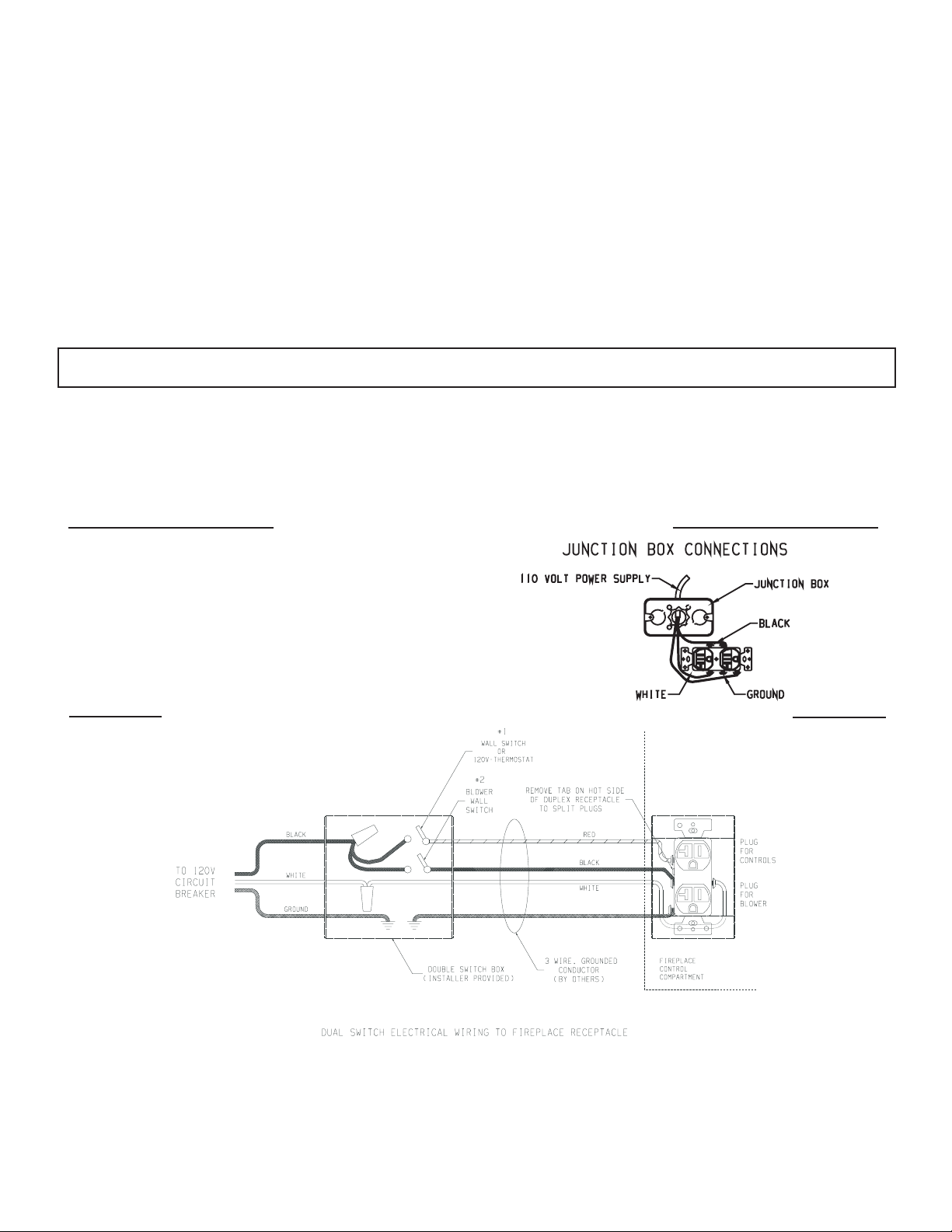
A factory installed junction box is located on the lower right
side of the replace. Wiring must be fed to the junction
box and attached to the receptacle that is provided. Leave
approximately 6" of wire in the junction box for connection.
Attach black wire to one side of the receptacle and white
wire to opposite side of receptacle. The ground wire should
be attached to the green (ground) screw.
120V DIRECT IGNITION VALVE OR INTERMITTENT PILOT MODELS
1. To wire Junction Box Receptacle, remove the tab on the
side of the receptacle (hot side) to split receptacle. This
will be required to separate blower and valve circuits.
2. Power for switched and live sides of Duplex Receptacle
must come from the same power source. (One circuit
breaker on main panel must switch all power off.)
3. From the wall box to the replace a 3-wire conductor
with ground is recommended, however (2) two-wire
conductors with grounds may be used in place of a
3-wire conductor with a ground if the black wires from
the thermostat and blower switch are identied.
4. Two wall switches, or a wall switch and thermostat may be
used to activate the two receptacle plugs independently.
18862-3-0414 Page 1Empire Comfort Systems Inc. • 918 Freeburg Avenue • Belleville, IL 62220
Page 2
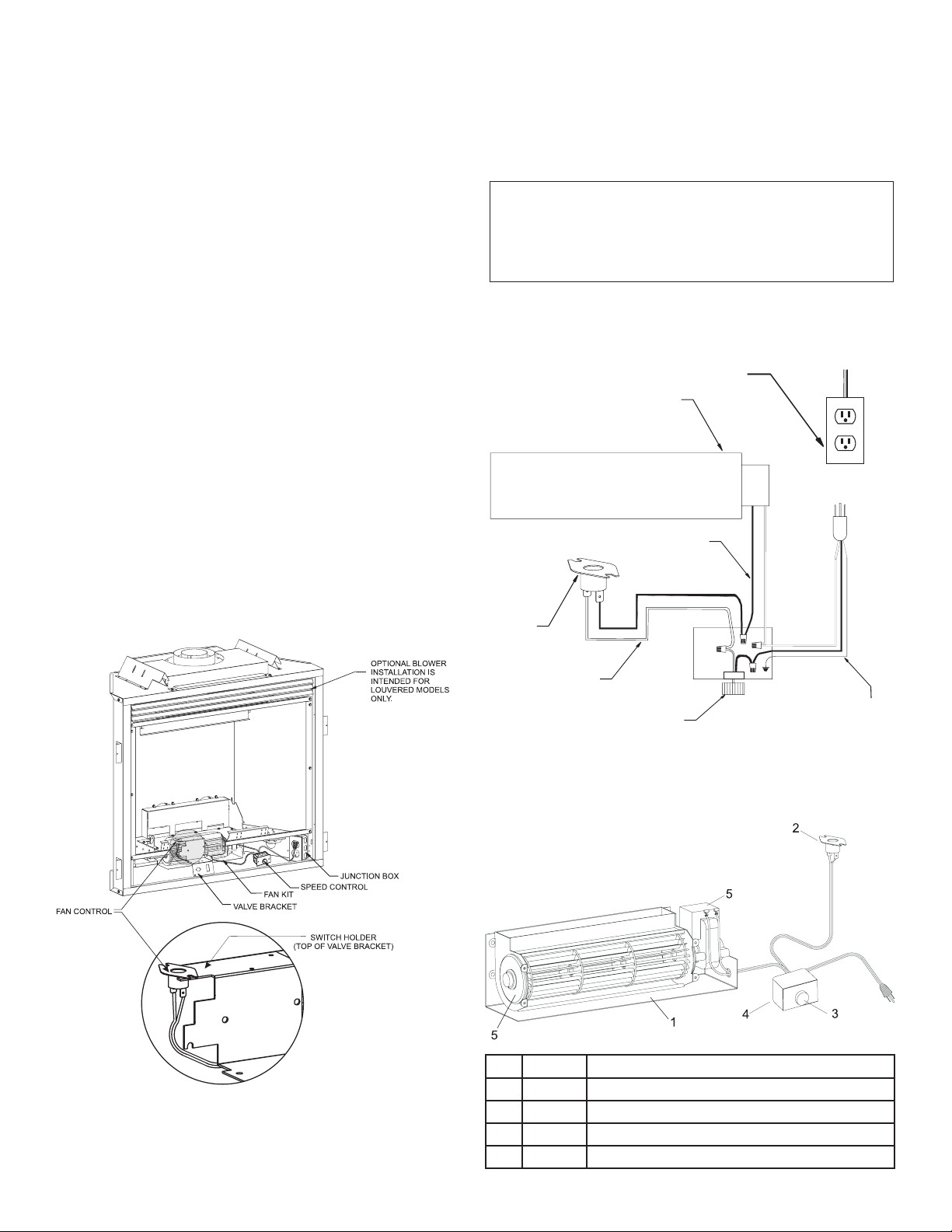
110 VOLT AC
JUNCTION BOX
WHITE
SPEED
CONTROL
FAN
CONTROL
GROUND
BLACK
FAN
Attention: If installed, do not damage gas inlet supply line
when blower assembly is inserted into replace. If
necessary, removal of the gas inlet supply line may
be necessary.
4. Remove upper louver and glass door assembly.
5. Insert blower assembly into interior, bottom of replace.
Position blower assembly behind gas valve, align notch on
back of blower assembly with center screw on replace back
and push blower assembly against replace back. The blower
wheel must be centered with the back wall of the replace.
Place blower assembly against the back wall. The magnets
on the back and bottom of blower assembly will sufciently
hold blower assembly in place.
6. Position speed control to the right of gas valve. Attach speed
control to bottom of replace. The magnets on bottom of
speed control will sufciently hold the speed control in place.
7. With base (ush face) of fan control switch facing upward,
insert base anges of fan control switch under the mounting
tabs on valve bracket. The base (ush face) of fan control
switch must be in contact with bottom of the rebox. (see
inset)
8. Insert power cord plug into junction box.
9. Install glass door and upper louver. Close bottom louver on
replace.
Note: This blower is equipped with a heat activated fan control
switch. Fan will operate when the replace warms up, and
will turn off when the replace cools down.
10. Installation of FBB4 optional variable speed blower assembly
is completed.
Blower Motor
The blower motor does not have oiling holes. Do not attempt to oil
the blower motor.
Blower Wheels
The blower wheels will collect lint and could require periodic
cleaning. If the air output decreases or the noise level increases, it
indicates a dirty blower wheel. Remove fan and clean blower wheels.
Warning: Unplugging of blower accessory will not stop
the heater from cycling. To turn off gas to the heater
(millivolt model): push in gas control knob slightly and
turn clockwise to "OFF." Do not force. To turn off gas on
direct ignition model, turn gas line valve to "OFF."
1 FBB4 BLOWER ASSEMBLY COMPLETE
2 R7649 FAN CONTROL
3 R4192 SPEED CONTROL KNOB
4 18879 SPEED CONTROL
5 R7731 BLOWER MOTOR AND WHEEL ASSEMBLY
18862-3-0414Page 2 Empire Comfort Systems Inc. • 918 Freeburg Avenue • Belleville, IL 62220
 Loading...