

Page 1
INSTALLATION INSTRUCTIONS
FBB21 BLOWER, AUTO VARIABLE-SPEED-TWIN
FOR USE ON DVCT(36,40) SERIES FIREPLACES
CAUTION: Sharp edges. Use protective gloves when installing.
GAS-FIRED
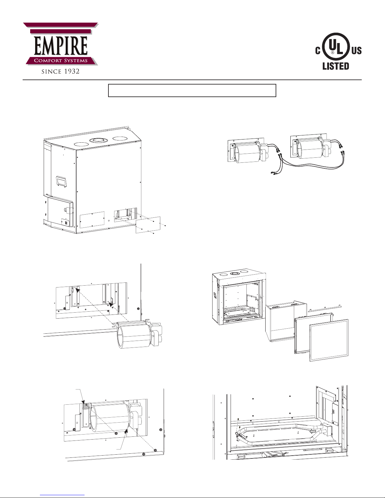
Bench Installation
1. Remove Blower Access Panels (Figure 1).
Figure 1
2. Place Blower onto blower brackets. (Figure 2)
4. Remove protective connectors on Wire Assembly from
replace and discard. Connect Wire Harness to both blowers
and the other end to the Wire Assembly supplied with the
replace. (Figure 4)
TO WIRE ASSEMBLY
(MODULE)
Figure 4
5. Replace Blower Access Panels removed in step 1. (Figure 1)
Installation After Placement of Unit in Wall
1. Remove the following items (Figure 5).
• Screen barrier (See Homeowner’s Manual, Maintenance
and Service).
• Glass Frame Assembly (See Homeowner’s Manual,
Maintenance and Service).
• Liners (See separate liner instruction document).
Figure 2
3. Hand bend tab as shown in (Figure 3) and secure with
(2) screws.
HAND BEND
TAB INWARD
HAND BEND
TAB INWARD
Figure 3
37001-3-1116 Page 1Empire Comfort Systems Inc. • Belleville, IL
Figure 5
2. Remove front and rear burner (Figure 6).
Figure 6
Page 2
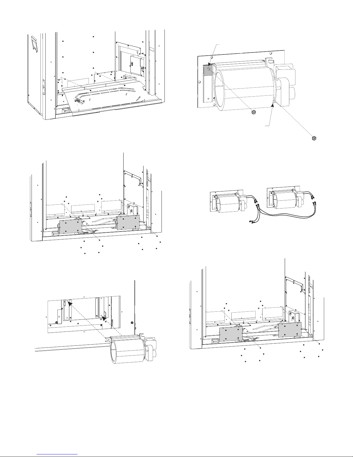
3. Remove burner base (Figure 7).
6. Hand bend tab as shown in (Figure 10) and secure with
(2) screws.
HAND BEND
TAB INWARD
Figure 7
4. Remove Blower Access Plates by taking out (6) screws each
(Figure 8).
Figure 8
5. Place Blower onto blower brackets (Figure 9).
HAND BEND
TAB INWARD
Figure 10
7. Remove protective connectors on Wire Assembly from
replace and discard. Connect Wire Harness to both blowers
and the other end to the Wire Assembly supplied with the
replace. (Figure 11)
TO WIRE ASSEMBLY
(MODULE)
Figure 11
8. Replace Blower Access Plates with (6) screws each.
(Figure 12)
.
Figure 9
Figure 12
9. Replace Screen Barrier, Glass Frame, and liners removed in
Step 1. (Figure 5)
37001-3-1116Page 2 Empire Comfort Systems Inc. • Belleville, IL
 Loading...