

Page 1
R-3159
INSTALLATION INSTRUCTIONS
REAR OUTLET, KIT NUMBER ROK-1
MODELS
FAW-40SPP AND FAW-40IP VENTED WALL FURNACES
INSTRUCTIONS MUST BE LEFT WITH THE OWNER FOR FUTURE REFERENCE AFTER INSTALLATION
Installing Optional Rear Outlet
Rear outlet kit, 10" boot assembly with register, ROK-1 for warm
air discharge into an adjoining room.
Attention: Before furnace is attached to the wall, the wall opening
for the rear outlet must be cut, in addition to removal of the outer
and inner casing knockouts on furnace.
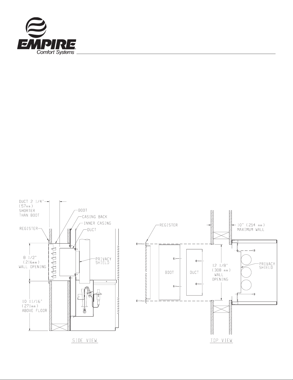
1. The wall opening measurements for the rear outlet are the following.
A. From floor to bottom of wall opening is 10 11/16".
B. From bottom of wall opening to top of wall opening is 8
1/2".
C. Wall opening width is 12 1/8".
2. Scribe a line between the four dimples on the outer casing back
to form a square. Drill a pilot hole within the scribed square
on the outer casing back. Remove the sheet metal within the
scribed square with a tin snips or comparable tool.
3. Remove the (4) #8 x 3/8" screws that attach the inner casing
close off plate to the inner casing.
4. Insert the privacy shield through the outer casing back and the
inner casing back. The privacy shield will be in front of the
inner casing back and behind the combustion chamber tubes.
Align clearance holes on privacy shield with screw holes on
inner casing back. Attach privacy shield to inner casing back
with (2) #8 x 3/8" screws provided. Attention: The (2) #8 x
3/8" screws must be inserted from the front of the furnace.
5. Attach furnace to wall (refer to Installation Instructions and
Owner's Manual).
6. Align clearance holes on 8" x 12" boot with screw holes on
outer casing back and mark boot to be flush with wall surface.
Remove boot and cut to proper length.
7. Attach 8" x 12" boot to outer casing back with (6) #8 x 3/8"
screws provided.
8. Align clearance holes on 6" x 10" duct with screw holes on
inner casing back and mark duct to be 2 1/4" shorter than 8" x
12" boot. Remove duct and cut to proper length.
9. Attach 6" x 10" duct to inner casing back with (4) #8 x 3/8"
screws removed in Step 3, 2 on top and 2 on bottom.
10. Insert rear register into 8" x 12" boot. Attach rear register to
wall with (2) #10 x 1" screws provided.
11. Installation of ROK-1 is completed.
R-3159
7/01
Empire Comfort Systems, Inc. Nine Eighteen Freeburg Ave. Belleville, Illinois 62222-0529
Page 1
Page 2

R-3159
INSTALLATION INSTRUCTIONS
REAR OUTLET, KIT NUMBER ROK-1
MODELS
FAW-55SPP AND FAW-55IP VENTED WALL FURNACES
INSTRUCTIONS MUST BE LEFT WITH THE OWNER FOR FUTURE REFERENCE AFTER INSTALLATION
Installing Optional Rear Outlet
Rear outlet kit, 10" boot assembly with register, ROK-1 for warm
air discharge into an adjoining room.
Attention: Before furnace is attached to the wall, the wall opening
for the rear outlet must be cut, in addition to removal of the outer
and inner casing knockouts on furnace.
Note: The privacy shield is not used on the FAW-55(SPP, IP) furnaces
and can be discarded.
1. The wall opening measurements for the rear outlet are the
following.
A. From floor to bottom of wall opening is 14 3/4".
B. From bottom of wall opening to top of wall opening is 8
1/2".
C. Wall opening width is 12 1/8".
2. Remove outer casing knockout from outer casing back.
3. Remove inner casing knockout from inner casing.
4. Attach furnace to wall (Refer to Installation Instructions and
Owner's Manual).
5. Align clearance holes on 8" x 12" boot with screw holes on
outer casing back and mark boot to be flush with wall surface.
Remove boot and cut to proper length.
6. Attach 8" x 12" boot to outer casing back with (6) #8x 3/8" screws
provided.
7. Align clearance holes on 6" x 10" duct with screw holes on
inner casing and mark duct to be 2 1/4" shorter than 8" x 12"
boot. Remove duct and cut to proper length.
8. Attach 6" x 10" duct to inner casing back with (4) #8x 3/8"
screws provided.
9. Insert rear register into 8" x 12" boot. Attach rear register to
wall with (2) #10 x 1" screws provided.
10. Installation of ROK-1 is completed.
Page 2 R-3159
Empire Comfort Systems, Inc. Nine Eighteen Freeburg Ave. Belleville, Illinois 62222-0529
7/01
Page 3

R-3159-F
INSTRUCTIONS POUR L’INSTALLATION
MODÈLES POUR LA SORTIE ARRIÈRE, ENSEMBLE NUMÉRO ROK-1
FAW-40SPP ET FAW-40IP RADIATEURS MURAUX AVEC ÉVENT
APRÈS L’INSTALLATION, LES INSTRUCTIONS DOIVENT RESTER AVEC LE PROPRIÉTAIRE POUR FUTURE RÉFÉRENCE.
Installation d’une Sortie Arrière Optionnelle
L’assemblage de sortie arrière, l’assemblage du trémie de 10" (254mm)
avec registre, le ROK-1 sert à l’évacuation d’air chaud dans une pièce
avoisinante.
Attention: Avant de fixer le radiateur au mur, vous devez couper l’ouverture
dans le mur pour la sortie arrière, en plus d’enlever les entrées défonçables
de la paroi intérieure et extérieure du radiateur.
1. Les mesures pour l’ouverture dans le mur de la sortie arrière sont les
suivantes.
A. Du plancher au bas de l’ouverture murale, la distance est de 10
11/16" (271mm).
B. Du bas de l’ouverture murale au haut de l’ouverture murale, la
distance est de 8 1/2" (216mm).
C. La largeur de l’ouverture murale est de 12 1/8" (308mm).
2. Tracer une ligne entre les quatre fossettes de la paroi extérieure arrière
pour former un carré. Percer un trou pilote à l’intérieur du carré que
vous avez tracé sur la paroi extérieure arrière. Enlever la feuille de
métal à l’intérieur du carré que vous avez tracé avec des ciseaux à
métal ou un outil comparable.
3. Enlever les (4) vis #8 x 3/8" (9mm) qui attachent la plaque de fermeture
de la paroi intérieure, à la paroi intérieure.
4. Insérer l’écran protecteur à travers la paroi extérieure arrière et la paroi
intérieure arrière. L’écran protecteur sera devant la paroi intérieure
arrière et derrière les tuyaux de la chambre de combustion. Aligner
les trous libres de l’écran protecteur avec les trous de vis de la paroi
intérieure arrière. Attacher l’écran protecteur à la paroi intérieure ar
rière avec (2) vis #8 x 3/8" (9mm). Les vis sont fournies. Attention:
Les (2) vis #8 x 3/8" (9mm) doivent être insérées à partir de l’avant
du radiateur.
5. Fixer le radiateur au mur (Référez-vous aux Instructions
pour l’Installation et Manuel du Propriétaire).
6. Aligner les trous libres du trémie de 8" x 12" (203mm x
305mm) avec les trous de vis de la paroi extérieure arrière et marquer
le trémie de façon à ce qu’il soit au niveau avec le mur. Enlever le
trémie et couper à la marque.
7. Fixer le trémie de 8" x 12" (203mm x 305mm) à la paroi ex
térieure arrière avec (6) vis #8 x 3/8" (9mm). Les vis sont fournies.
8. Aligner les trous libres du conduit de 6" x 10" (152mm x
254mm) avec les trous de vis de la paroi intérieure arrière et marquer
le conduit pour qu’il soit 2 1/4" (57mm) plus petit que le trémie de 8" x
12" (203mm x 305mm). Enlever le conduit et couper à la marque.
9. Fixer le conduit de 6" x 10" (152mm x 254mm) à la paroi
intérieure arrière en utilisant les 4 vis #8 x 3/8" (9mm) que vous avez
enlevées à l’étape 3, 2 en haut et 2 en bas.
10. Insérer le registre arrière dans le trémie de 8" x 12" (203mm x 305mm).
Fixer le registre arrière au mur avec (2) vis #10 x 1" (25mm). Les vis
sont fournies.
11. L’installation du ROK-1 est complétée.
-
-
R-3159
7/01
VUE DE DESSUS
Empire Comfort Systems, Inc. Nine Eighteen Freeburg Ave. Belleville, Illinois 62222-0529
Page 1
Page 4

R-3159-F
INSTRUCTIONS POUR L’INSTALLATION
MODÈLES POUR LA SORTIE ARRIÈRE, ENSEMBLE NUMÉRO ROK-1
FAW-55SPP ET FAW-55IP RADIATEURS MURAUX AVEC ÉVENT
APRÈS L’INSTALLATION, LES INSTRUCTIONS DOIVENT RESTER AVEC LE PROPRIÉTAIRE POUR FUTURE RÉFÉRENCE.
Installation d’une Sortie Arrière Optionnelle
L’assemblage de sortie arrière, l’assemblage du trémie de 10" (254mm)
avec registre, le ROK-1 sert à l’évacuation d’air chaud dans une pièce
avoisinante.
Attention: Avant de fixer le radiateur au mur, vous devez couper l’ouverture
dans le mur pour la sortie arrière, en plus d’enlever les entrées défonçables
de la paroi intérieure et extérieure du radiateur.
Note: L’écran protecteur n’est pas utilisé pour les radiateurs FAW-55(SPP,
IP) et peut être jeté.
1. Les mesures pour l’ouverture dans le mur de la sortie arrière sont les
suivantes.
A. Du plancher au bas de l’ouverture murale, la distance est de 14
3/4" (375mm).
B. Du bas de l’ouverture murale au haut de l’ouverture murale, la
distance est de 8 1/2" (216mm).
C. La largeur de l’ouverture murale est de 12 1/8" (308mm).
2. Enlever l’entrée défonçable qui se trouve sur la paroi extérieure
arrière.
3. Enlever l’entrée défonçable qui se trouve sur la paroi
intérieure.
4. Fixer le radiateur au mur (Référez-vous aux Instructions pour
l’Installation et Manuel du Propriétaire).
5. Aligner les trous libres du trémie de 8" x 12" (203mm x
305mm) avec les trous de vis de la paroi extérieure arrière et marquer
le trémie de façon à ce qu’il soit au niveau avec le mur. Enlever le
trémie et couper à la marque.
6. Fixer le trémie de 8" x 12" (203mm x 305mm) à la paroi extérieure
arrière avec (6) vis #8 x 3/8" (9mm). Les vis sont fournies.
7. Aligner les trous libres du conduit de 6" x 10" (152mm x
254mm) avec les trous de vis de la paroi intérieure arrière et marquer
le conduit pour qu’il soit 2 1/4" (57mm) plus petit que le trémie de 8" x
12" (203mm x 305mm). Enlever le conduit et couper à la marque.
8. Fixer le conduit de 6" x 10" (152mm x 254mm) à la paroi
intérieure arrière en utilisant 4 vis #8 x 3/8" (9mm). Les vis sont
fournies.
9. Insérer le registre arrière dans le trémie de 8" x 12" (203mm
x 305mm). Fixer le registre arrière au mur avec (2) vis #10 x 1"
(25mm). Les vis sont fournies.
10. L’installation du ROK-1 est complét
ée.
VIS 25mm
OUVERTURE
MURALE DE
216mm
Page 2 R-3159
Empire Comfort Systems, Inc. Nine Eighteen Freeburg Ave. Belleville, Illinois 62222-0529
OUVERTURE
MURALE DE
308mm
COUPER LE CONDUIT
57mm PLUS PETIT QUE LE
TRÉMIE
COUPER LE TRÉMIE POUR
QU’IL SOIT AU NIVEAU
AVE C LE MUR A PRÈ S
L’INSTALLATION.
7/01
 Loading...