

Page 1

INSTALLATION INSTRUCTIONS
AND
OWNER'S MANUAL
FAN TYPE
VENTED
WALL FURNACE
MODEL
FAW-40-1SPP
FAW-40-1IP
Installer: Please leave these instructions with the
consumer.
Consumer: Please retain these instructions for
future use.
WARNING: If not installed, operated and
maintained in accordance with the manufacturer's instructions, this product could
expose you to substances in fuel or from
fuel combustion which can cause death or
serious illness.
EFFECTIVE DATE
SEPTEMBER 2003
WARNING: If the information in this
manual is not followed exactly, a fir e or
explosion may result causing property
damage, personal injury or loss of life.
— Do not store or use gasoline or other
flammable vapors and liquids in the vicinity of this or any other appliance.
— WHAT TO DO IF YOU SMELL GAS
• Do not try to light any appliance.
• Do not touch any electrical switch; do
not use any phone in your building.
• Immediately call your gas supplier
from a neighbor's phone. Follow the
gas supplier's instructions.
• If you cannot reach your gas supplier ,
call the fire department.
— Installation and service must be per-
formed by a qualified installer, service
agency or the gas supplier.
12427-2-0903
Page 1
Page 2

Introduction
Always consult your local Building Department regarding regulations,
codes or ordinances which apply to the installation of a vented wall
furnace.
Instructions to Installer
1. Installer must leave instruction manual with owner after installation.
2. Installer must have owner fill out and mail warranty card supplied
with furnace.
3. Installer should show owner how to start and operate furnace and
thermostat.
Warning:
Any change to this furnace or its control can be dangerous. This
is a heating appliance and any panel, door or guard removed
for servicing an appliance must be replaced prior to operating
the appliance.
General Information
This series is design certified in accordance with American National
Standard / CSA Standard Z21.86 and CSA 2.32 by the Canadian
Standards Association, as a Fan Type Vented Wall Furnace and must be
installed according to these instructions.
Any alteration of the original design, installed other than as shown
in these instructions or use with a type of gas not shown on the rating
plate is the responsibility of the person and company making the
change.
Important
All correspondence should refer to complete Model No., Serial No. and
type of gas.
Notice: During initial firing of this unit, its paint will bake out and smoke
will occur. To prevent triggering of smoke alarms, ventilate the room in
which the unit is installed.
Installation on Rugs and Tile
If this appliance is installed directly on carpeting, tile or other combustible
material other than wood flooring the appliance shall be installed on a
metal or wood panel extending the full width and depth of the appliance.
The base referred to above does not mean the fire-proof base as used on
wood stoves. The protection is for rugs that are extremely thick and light
colored tile.
Installation in Residential Garages
Gas utilization equipment in residential garages shall be installed so that
all burners and burner ignition devices are located not less than 18"
(457mm) above the floor.
Such equipment shall be located, or protected, so it is not subject to
physical damage by a moving vehicle.
Specifications
Model FAW-40SPP FAW-40IP
Input BTU/HR (KW/H) 40,000 (11.7) 40,000 (11.7)
Height 72 1/2" (184.2cm) 72 1/2" (184.2cm)
Width 14 1/8" (35.9mm) 14 1/8" (35.9mm)
Depth 10 3/8" (26.4mm) 10 3/8" (26.4mm)
Gas Inlet Pipe 1/2" (1.27cm) 1/2" (1.27cm)
Vent Collar Type B Oval 4" (10.2cm) 4" (10.2cm)
CFM 275 275
Accessories
Register, side outlet, fixed register SOR-1
Side outlet, 10" (254mm) SOK-1
maximum extension, fixed register
Rear Outlet, 10" (254mm) ROK-1
maximum extension, adjustable register
Vent enclosure, 24" (61cm) FVE-24
[for rooms up to 96 1/2" (245cm) in height]
Vent enclosure, 34" (86cm) FVE-34
[for rooms up to 106 1/2" (270.5cm) in height]
Vent enclosure, 46" (117cm) FVE-46
[for rooms up to 118 1/2" (301cm) in height]
Oval-to-Round flue adapter kit 4" (102mm) DV-648
THIS IS A HEATING APPLIANCE
DO NOT OPERATE THIS APPLIANCE WITHOUT FRONT PANELS INSTALLED.
• Due to high temperatures the appliance should be located out
of traffic and away from furniture and draperies.
• Children and adults should be alerted to the hazards of high
surface temperatures and should stay away to avoid burns or
clothing ignition.
• Young children should be carefully supervised when they are
in the same room as the appliance.
• Clothing or other flammable material should not be placed on
or near the appliance.
• Any safety screen or guard removed for servicing an appliance
must be replaced prior to operating the appliance.
• Keep burner and control compartment clean.
• Installation and repair should be done by a QUALIFIED
SERVICE PERSON. The appliance should be inspected
before use and at least annually by a qualified service person.
More frequent cleaning may be required due to excessive lint
from carpeting, bedding materials, etc. It is imperative that
control compartments, burners and circulating air passageways of the appliance be kept clean.
• DO NOT put anything around the furnace that will obstruct
Page 2
the flow of combustion and ventilation air.
• DO keep the appliance area clear and free from combustible
material, gasoline and other flammable vapors and liquids.
• DO examine venting system periodically and replace damaged parts.
• DO make a periodic visual check of pilot and burners. Clean
and replace damaged parts.
• CAUTION: Pilot hole cover must be kept tightly closed
during operation.
• DO NOT use this heater if any part has been under water.
Immediately call a qualified service technician to inspect the
heater and to replace any part of the control system and any
gas control which has been under water.
• This furnace must not be connected to a chimney flue serving
a separate solid-fuel burning appliance.
• IMPORTANT: This furnace has a washable permanent
type filter in the door which should be cleaned at least once
per year before the heating season. For dirty or high use
areas more frequent cleaning is required.
12427-2-0903
Page 3

SAFETY INFORMATION FOR USERS OF LP-GAS
Propane (LP-Gas) is a flammable gas which can cause fires
and explosions. In its natural state, propane is odorless and
colorless. You may not know all the following safety precautions which can protect both you and your family from an
accident. Read them carefully now, then review them point
LP-GAS WARNING ODOR
If a gas leak happens, you should be able to smell the gas because of the odorant put in the LP-Gas.
That's your signal to go into immediate action!
by point with the members of your household. Someday
when there may not be a minute to lose, everyone's safety will
depend on knowing exactly what to do. If, after reading the
following information, you feel you still need more information, please contact your gas supplier.
• Do not operate electric switches, light matches, use your
phone. Do not do anything that could ignite the gas.
• Get everyone out of the building, vehicle, trailer, or area. Do
that IMMEDIATELY.
• Close all gas tank or cylinder supply valves.
• LP-Gas is heavier than air and may settle in low areas such
as basements. When you have reason to suspect a gas leak,
keep out of basements and other low areas. Stay out until
NO ODOR DETECTED - ODOR FADE
Some people cannot smell well. Some people cannot smell
the odor of the chemical stench put into the gas. You must
find out if you can smell the odorant in propane. Smoking can
decrease your ability to smell. Being around an odor for a time
can affect your sensitivity or ability to detect that odor. Sometimes other odors in the area mask the gas odor. People may not
smell the gas odor or their minds are on something else. Thinking about smelling a gas odor can make it easier to smell.
The odorant in LP-gas is colorless, and it can fade under
some circumstances. For example, if there is an underground
leak, the movement of the gas through soil can filter the odorant.
Odorants in LP-Gas also are subject to oxidation. This fading
firefighters declare them to be safe.
• Use your neighbor's phone and call a trained LP-Gas service
person and the fire department. Even though you may not
continue to smell gas, do not turn on the gas again. Do not
re-enter the building, vehicle, trailer, or area.
• Finally, let the service man and firefighters check for
escaped gas. Have them air out the area before you return.
Properly trained LP-Gas service people should repair the
leak, then check and relight the gas appliance for you.
can occur if there is rust inside the storage tank or in iron gas
pipes.
The odorant in escaped gas can adsorb or absorb onto or into
walls, masonry and other materials and fabrics in a room. That
will take some of the odorant out of the gas, reducing its odor
intensity.
LP-Gas may stratify in a closed area, and the odor intensity could
vary at different levels. Since it is heavier than air, there may be
more odor at lower levels. Always be sensitive to the slightest
gas odor. If you detect any odor, treat it as a serious leak.
Immediately go into action as instructed earlier.
SOME POINTS TO REMEMBER
• Learn to recognize the odor of LP-gas. Your local LP-Gas
Dealer can give you a "Scratch and Sniff" pamphlet. Use it
to find out what the propane odor smells like. If you suspect
that your LP-Gas has a weak or abnormal odor, call your LPGas Dealer.
• If you are not qualified, do not light pilot lights, perform
service, or make adjustments to appliances on the LP-Gas
system. If you are qualified, consciously think about the odor
of LP-Gas prior to and while lighting pilot lights or performing service or making adjustments.
• Sometimes a basement or a closed-up house has a musty
smell that can cover up the LP-Gas odor. Do not try to light
pilot lights, perform service, or make adjustments in an area
where the conditions are such that you may not detect the
odor if there has been a leak of LP-Gas.
• Odor fade, due to oxidation by rust or adsorption on walls of
new cylinders and tanks, is possible. Therefore, people
should be particularly alert and careful when new tanks or
cylinders are placed in service. Odor fade can occur in new
tanks, or reinstalled old tanks, if they are filled and allowed
12427-2-0903
to set too long before refilling. Cylinders and tanks which
have been out of service for a time may develop internal rust
which will cause odor fade. If such conditions are suspected
to exist, a periodic sniff test of the gas is advisable. If you
have any question about the gas odor, call your LP-gas
dealer. A periodic sniff test of the LP-gas is a good safety
measure under any condition.
• If, at any time, you do not smell the LP-Gas odorant and you
think you should, assume you have a leak. Then take the
same immediate action recommended above for the occasion
when you do detect the odorized LP-Gas.
• If you experience a complete "gas out," (the container is
under no vapor pressure), turn the tank valve off immediately. If the container valve is left on, the container may draw
in some air through openings such as pilot light orifices. If
this occurs, some new internal rusting could occur. If the
valve is left open, then treat the container as a new tank.
Always be sure your container is under vapor pressure by
turning it off at the container before it goes completely empty
or having it refilled before it is completely empty.
Page 3
Page 4
Ventilation and Combustion Air
WARNING: Danger of property damage, bodily injury or death,
this furnace and any other fuel burning appliance must be
provided with enough fresh air for proper combustion and
ventilation of flue gases. Most homes will require that outside air
be supplied. Do not draw air from a corrosive environment such
as a workshop or laundry room.
The requirements for providing air for combustion and ventilation are
listed in the National Fuel Gas Codes NFPA 54/ANSI Z223.1 (in
Canada - CAN/CGA B149).
Note: Air requirements for operation of exhaust fans, kitchen ventilation
systems, clothes dryers, fireplace and any other fuel burning or ventilating
equipment used in the space must be considered in determining
combustion air requirements.
Ventilation Air Openings and Ducts
In determining the free area needed consideration must be given to the
blocking effect of louvers, grills or screens protecting openings.
— If a screen is used to cover openings it must not be smaller than 1/4"
mesh.
— Use the free area of a louver or grill to determine the size opening
required to provide the free area specified. If the free area is not
known assume a 20% free area for wood and a 60% free area for a
metal louver or grill.
— Ducts must have the same cross sectional area as the free area of the
openings to which they connect.
— The minimum dimension of air ducts must not be less than 3 inches.
Installation in an Unconfined Space
An unconfined space is an area including all rooms not separated by
doors with a volume greater than 50 cubic feet per 1,000 Btuh of the
combined total input rates of all appliances which draw combustion air
from that space. For example, a space including a water heater rated at
40,000 Btuh input and a furnace rated at 40,000 Btuh requires a volume
of 4,000 cubic feet (50 x (40 + 40) = 4,000) to be considered as
unconfined. If the space has an 8 ft. ceiling, the floor area of the space
must be 500 sq. ft. In general, particularly in older homes, a furnace
installed in an unconfined space will not require outside air for
combustion. However in a "tight" newly constructed home, outside air
may be necessary to insure adequate combustion.
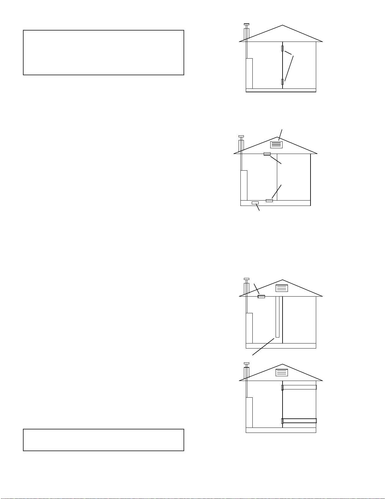
Installation in a Confined Space
A confined space is an area with volume less than 50 cubic feet per 1,000
Btuh of the combined input rates of all appliances drawing combustion
air from that space. Small areas such as equipment rooms are confined
spaces. Furnaces installed in a confined space which supply heated air
to areas outside the space must draw return air from outside the space
through tightly sealed return air ducts. A confined space must have 2
openings into the space for combustion air. One opening must be within
12 inches of the ceiling and the other must be within 12 inches of the
floor. The required sizing of these openings is determined by whether
inside or outside air is used to support combustion, the method by which
the air is brought to the space (vertical or horizontal duct) and by the total
input rate of all appliances in the space. See Figure 1.
All Air From Inside — Confined Space
If combustion air is taken from the heated space the 2 openings must
each have a free area of at least one square inch per 1,000 Btuh of total
input of all appliances in the confined space but not less than 100 square
inches (645cm
For example: for a 40,000 Btuh furnace only in the confined space each
opening must be 100 square inches (645cm
2
) of free area.
2
) each of free area.
furnace
confined
space
opening
Figure 1
Outdoor Air
Outlet and inlet air can be brought into the confined space via openings
into a ventilated attic and ventilated crawl space.
attic ventilation louvers
furnace
crawl space ventilation louvers
outlet air
inlet air
Figure 2
Confined Space
Outdoor Air Using Vertical or Horizontal Ducts
If combustion air is taken from outdoors through vertical ducts, the
openings and ducts must have a minimum free area of one square inch
2
(6.5cm
) per 4,000 Btuh of total appliance input. In installations
drawing combustion air from a ventilated attic both air ducts must
extend above the attic insulation.
outlet air
furnace
inlet air ends one foot above floor
furnace
vertical
outlet air duct
inlet air duct
WARNING: Combustion air must not be drawn from a heated
space which includes exhaust fans, fireplaces or other devices that
may produce a negative pressure in the space.
Page 4
horizontal
Figure 3
If combustion air is taken from outdoors through horizontal ducts the
openings and ducts must have a minimum free area of one square inch
2
(6.5cm
) per 2,000 Btuh of total appliance input.
12427-2-0903
Page 5

Qualified Installing Agency
Installation and replacement of gas piping, gas utilization equipment or
accessories and repair and servicing of equipment shall be performed
only by a qualified agency. The term "qualified agency" means any
individual, firm, corporation or company which either in person or
through a representative is engaged in and is responsible for (a) the
installation or replacement of gas piping or (b) the connection, installation,
repair or servicing of equipment, who is experienced in such work,
familiar with all precautions required and has complied with all the
requirements of the authority having jurisdiction.
The installation must conform with local codes or, in the absence of local
codes, with the National Fuel Gas Code, ANSI Z223.1/NFPA 54*
Natural and Propane Installation Code, CSA B149.1.
*Available from the American National Standards Institute, Inc., 11 West 42nd St., New
York, N.Y. 10036.
Clearances
1. In selecting a location for installation, it is necessary to provide
adequate accessibility clearances for servicing and proper installation.
2. The FAW-40 can be attached to the wall or recessed into the wall up
to 9 1/2 inches (24.1cm) in depth. Note:
Do not place combustible
header or material on top of unit when installed in wall.
Maintain 3/4" minimum spacing above heater.
3. The wall in which the furnace is recessed has (0) zero (0mm)
clearance to the furnace sides.
4. When using side discharge registers, SOR-1 or SOK-1, the furnace
cannot be recessed into the wall.
5. Clearance to sidewall or combustible material is 4 inches (10.2cm).
6. Ceiling clearance is 4 inches (10.2cm).
7. Floor and rear wall clearance is (0) zero inches (0mm).
8. Clearance of 18 inches (46cm) is required to adjacent wall or
combustible material when flush mounted SOR-1, side outlet register
is used.
Before Installing Consider The Following Venting
1. A chimney for residential-type or low-heat gas utilization equipment
shall extend at least 3 feet (914mm) above the highest point where
it passes through a roof of a building and at least 2 feet (610mm)
higher than any portion of building within a horizontal distance of 10
feet (3m).
2. This furnace must not be connected to a chimney flue serving a
separate solid-fuel burning appliance.
3. Uninsulated Single-Wall Metal Pipe shall not be used outdoors
in cold climates for venting gas utilization equipment.
4. Attention! This Fan Type Vented Wall Furnace is equipped with a
vent safety switch. In the event of spillage of flue products due to
improper venting the vent safety switch will open, which results in
the main burners to "shut off".
Model No. FAW-40 may be vented as shown in Figure 4. The vent
cap termination must be at least 12 feet (3.7m) above the floor and
must exhaust to the outdoors.. Clearance to combustible construction
is held by the fixed spacers at 1 inch (25mm) with B-1 or (B-W) vent
pipe. Installation must conform to local codes.
A. 4" (102mm) Round (all parts purchase locally except Item 2)
1. Type B-1 round pipe
2. Part No. DV-648, 4" (102mm) oval-to-round flue adapter kit
(see accessories)
3. Single story type B-1 gas vents require a baseplate and one
pair of ceiling plate spacers.
4. Multi-story type B-1 gas vents require a baseplate, one pair of
ceiling plate spacers at the first floor ceiling and one pair of
fire stop spacers at each successive ceiling level.
B. 4" (102mm) Oval (all parts purchase locally)
1. Type B-1 oval pipe or B-W vent pipe
2. Single story type B-1 or (B-W) gas vents require a baseplate
and one pair of ceiling plate spacers.
3. Multi-story type B-1 or (B-W) gas vents require a baseplate,
one pair of ceiling plate spacers at the first floor ceiling and
one pair of fire stop spacers at each successive ceiling level.
C. 4" (102mm) Oval In-The-Wall (all parts purchase locally)
1. Type B-1 oval pipe or B-W vent pipe
2. Type B-1 oval elbows or B-W oval elbows
3. Single story type B-1 or (B-W) gas vents require a baseplate
and one pair of ceiling plate spacers.
4. Multi-story type B-1 or (B-W) gas vents require a baseplate,
one pair of ceiling plate spacers at the first floor ceiling and
one pair of fire stop spacers at each successive ceiling level.
Stud space around gas vents must be free of obstructions and
building paper.
4" ROUND
VENT
ENCLOSURE
WALL
ADAPTER
BASEPLATE
A.
SIDE
4" B-1 OVAL
BRACKET
BASEPLATE
FRONT
B.
4" B-1 OVAL
4" 45 DEG.
OVAL ELBOWS
SPACER
BASEPLATE
C.
4" B-1 OVAL
SPACER
C.
BASEPLATE
Figure 4
12427-2-0903
Page 5
Page 6

Page 6
12427-2-0903
Page 7

8. Align clearance holes on 6" x 10" (152mm x 254mm) duct with
screw holes on inner casing back and mark duct to be 2 1/4" (57mm)
shorter than 8" x 12" (203mm x 305mm) boot. Remove duct and cut
to proper length.
9. Attach 6" x 10" (152mm x 254mm) duct to inner casing back with (4)
#8 x 3/8" (9mm)screws removed in Step 3, 2 on top and 2 on bottom.
10. Insert rear register into 8" x 12" (203mm x 305mm) boot. Attach
rear register to wall with (2) #10 x 1"(25mm) screws provided.
11. Installation of ROK-1 is completed.
Locating Furnace On Wall
The furnace is to be located on a wall. The furnace is 14 1/8" (35.9cm)
in width and can be recessed into the wall with typical stud spacing.
A template is provided in furnace carton for locating gas line connection.
Also, refer to Figure 7 for positioning the furnace on wall and for
locating gas line connection.
Locating Gas Supply
The gas line can enter the furnace either through the floor or wall. The
gas line opening should be made at this time. Location of the opening
will be determined by the position of floor joists and the valve and union
used for servicing. See Figure 7.
72 3/4"
14 3/8"
CUT OUT OPENING FOR RECESSED MOUNTING
Attention! The 7/8" (22mm) strain relief bushing is located within the
same yellow envelope as the Installation Instructions and Owner's
Manual.
Attaching Furnace to Wall
When attaching furnace to the wall remove that portion of baseboard and
molding on the wall which is behind the furnace. Attach furnace to wall,
at the outer casing top, with (2) toggle bolts provided and to floor, at the
outer casing bottom, with (2) #10 x 1 1/2" (38mm) screws provided.
Gas Supply
Check all local codes for requirements, especially for the size and type
of gas supply line required. On Natural gas lines less than 75' (22.9m)
long, use 1/2" (13mm) pipe; on longer runs, use 3/4" (19mm) iron pipe
or equal. On LP gas lines please consult LP gas supplier.
Installing a New Main Gas Cock
Each appliance should have its own manual gas cock.
A manual main gas cock should be located in the vicinity of the unit.
Where none exists, or where its size or location is not adequate, contact
your local authorized installer for installation or relocation.
Compounds used on threaded joints of gas piping shall be resistant to the
action of liquefied petroleum gases. The gas lines must be checked for
leaks by the installer. This should be done with a soap solution watching
for bubbles on all exposed connections, and if unexposed, a pressure test
should be made.
Never use an exposed flame to check for leaks. Appliance must be
disconnected from piping at inlet of control valve and pipe capped
or plugged for pressure test. Never pressure test with appliance
connected; control valve will sustain damage!
A gas valve and ground joint union should be installed in the gas line
upstream of the gas control to aid in servicing. It is required by the
National Fuel Gas Code that a drip line be installed near the gas inlet.
This should consist of a vertical length of pipe tee connected into the gas
line that is capped on the bottom in which condensation and foreign
particles may collect.
GAS LINE
HOLE 1 1/4"
2 1/8"
4"
4"
GAS LINE/ELECTRICAL OPENINGS FOR
RECESSED AND SURFACE MOUNT
ELECTRICAL WIRING HOLE
RECESSED MOUNTING
LOCATION
8"
Figure 7
Locating Electric Supply
A 7/8" (22mm) diameter knockout is provided at the bottom of the left
and right side panels. A three-prong (grounding) plug assembly is
located within the control compartment (bottom) of the furnace. Please
remove 7/8" (22mm) knockout from appropriate side panel when
routing plug assembly to an electrical outlet.
Installation of Three-prong (Grounding) Plug Assembly
1. Disconnect nylon cap on 3' (914mm) plug assembly from nylon plug
on wiring harness. Remove 3' (914mm) plug assembly from control
compartment (bottom) of the furnace.
2. Remove 7/8" (22mm) knockout from appropriate side panel.
3. Insert nylon cap on 3' (914mm) plug assembly into the 7/8" (22mm)
hole in the side panel.
4. Connect nylon cap on 3' (914mm) plug assembly to nylon plug on the
wiring harness.
5. Place 7/8" (22mm) strain relief bushing around the cord of the 3'
(914mm) plug assembly. Insert 7/8" (22mm) strain relief bushing
into the 7/8" (22mm) hole in the side panel.
Figure 8
Method of Installing a Tee Fitting Sediment Trap
The use of the following gas connectors is recommended:
— ANS Z21.24 Appliance Connectors of Corrugated Metal Tubing
and Fittings
— ANS Z21.45 Assembled Flexible Appliance Connectors of Other
Than All-Metal Construction
The above connectors may be used if acceptable by the authority having
jurisdiction.
Pressure Testing of the Gas Supply System
1. To check the inlet pressure to the gas valve, a 1/8" (3mm) N.P.T.
plugged tapping, accessible for test gauge connection, must be
placed immediately upstream of the gas supply connection to the
appliance.
2. The appliance and its individual shutoff valve must be disconnected
from the gas supply piping system during any pressure testing of that
system at test pressures in excess of 1/2 psig (3.5 kPa).
3. The appliance must be isolated from the gas supply piping system by
closing its individual manual shutoff valve during any pressure
testing of the gas supply piping system at test pressures equal to or
less than 1/2 psig (3.5 kPa).
12427-2-0903
Page 7
Page 8

Attention! If one of the above procedures results in pressures in excess
of 1/2 psig (14" w.c.) (3.5 kPa) on the appliance gas valve, it will result
in a hazardous condition.
Checking Manifold Pressure
Both Propane and Natural gas valves have a built-in pressure regulator
in the gas valve. Natural gas models will have a manifold pressure of
approximately 4.0" w.c. (.996kPa) at the valve outlet with the inlet
pressure to the valve from a minimum of 5.0" w.c. (1.24kPa) for the
purpose of input adjustment to a maximum of 10.5" w.c. (2.615kPa).
Propane gas models will have a manifold pressure approximately 10.0"
w.c. (2.49kPa) at the valve outlet with the inlet pressure to the valve from
a minimum of 11.0" w.c. (2.739kPa) for the purpose of input adjustment
to a maximum of 13.0" w.c. (3.237kPa).
A 1/8" (3mm) N.P.T. plugged tapping, accessible for test gauge
connection, is located on the outlet side of the gas control.
The built-in regulator comes on at approximately 1/4th pressure and full
on in 10 seconds.
from the burner box, remove each main burner. Pilot mounting bracket
will need to be unscrewed and moved out of the way to remove all
burners. Burners can be blown out using compressed air or by blowing
through them. Be sure there is no lint or foreign debris blocking the
burner ports. Reassemble using the same screws earlier removed and
locate pilot in the same position as before and noted above.
THERMOCOUPLE
BURNER
SPARK
ELECTRODE
PILOT
STANDING PILOT
Figure 9
High Altitudes
For altitudes/elevations above 2,000 feet (610m), input ratings should
be reduced at the rate of 4 percent for each 1,000 feet (305m) above sea
level. For Canadian high altitude applications, this appliance is suitable
for installation at elevations between 0 feet (0m) and 4,500 feet (1,372m)
without change.
Piezo Pilot Ignitor Instructions
Depressing the red button completely causes a spark to occur at the pilot.
This is a substitute for a match which requires opening the pilot hole
cover.
To light the pilot, it is important that the electrode be 1/8" (3mm) from
the thermocouple. The spark must occur at the point the burner flame
hits the thermocouple. The end of the electrode will be red hot with the
pilot on.
On a new installation with air in the gas line, it is suggested that a match
be used. The match will light the pilot faster than the piezo under this
condition.
Proper Pilot Flame
The correct pilot flame (Figure 10) will be blue, extending past the
thermocouple. The flame will surround the thermocouple just below the
tip.
Natural gas pilots require adjusting when the inlet gas pressure is above
5" w.c. (1.245kPa). Remove the pilot cover screw on the control valve
(Figure 9), and turn the adjustment screw clockwise to reduce flame.
Replace pilot cover screw to eliminate gas leakage.
LP gas (propane) will not require adjustment.
After use, cleaning may be required for the proper flame.
Proper Main Burner Flame
The correct flame will be a short, blue inner flame with a much larger,
light blue, outer flame. The burner does not have a primary air adjustment.
The flame will be correct if the factory-set pressure and orifice opening
are used. After the furnace has been operating, the burner ports may be
blocked by foreign matter carried in by combustion air. Therefore,
cleaning of the burner may be needed for proper flame.
To clean burner port disconnect the gas supply to the valve, and remove
the screws fastening the burner door. After removing the burner door
THERMOCOUPLE
SPARK
ELECTRODE
PILOT LOCATION END VIEW
STANDING PILOT SHOWN
3/8" TO 1/2"
PILOT FLAME
PILOT
HOT SURFACE
IGNITOR
IP-MODEL PILOT
FLAME
ROD
PILOT SHIELD
GROUND
ELECTRODE
BURNER
Figure 10
Figure 11
Cleaning Combustion (Exchanger) Assembly
A QUALIFIED SERVICE PERSON should remove the combustion
(exchanger) assembly and flue baffles. Apply air pressure to the inside
of the combustion (exchanger) assembly and flue baffles in order to
clear all passageways.
Page 8
12427-2-0903
Page 9

Oiling the Motor
The fan motor should be cleaned and oiled once each heating season. Oil
holes are located on the top at each end of the motor. Use a few drops of
#10 motor oil. To clean the motor, blow air through its ventilation
openings with a vacuum cleaner or low pressure air source.
Wiring
The appliance, when installed, must be electrically grounded in
accordance with local codes or, in the absence of local codes, with the
National Electrical Code, ANSI/NFPA 70 or Canadian Electrical Code,
CSA C22.1, if an external electrical source is utilized. This appliance
is equipped with a three-prong [grounding] plug for your protection
against shock hazard and should be plugged directly into a properly
grounded three-prong receptacle. Do not cut or remove the
grounding prong from this plug. For an ungrounded receptacle, an
adapter, which has two prongs and a wire for grounding, can be
purchased, plugged into the ungrounded receptacle and its wire connected
to the receptacle mounting screw. With this wire completing the ground,
the appliance cord plug can be plugged into the adapter and be electrically
grounded. A 7/8" (22mm) hole is provided in the junction box for use
with a conduit connector if local codes require this type of protection.
Thermostat Installation
The thermostat should be installed in the same room as the furnace 4'
(1.2m) to 5' (1.5m) above the floor and away from another heat source
(cooking stove, hot water heater, etc.) including walls and doorways
with a heat source in an adjoining room. Do Not Install Thermostat on
Outside Wall.
Insulated Vent Enclosure
Vented wall furnaces installed in buildings with flat roofs can have poor
venting. The cold vent pipe will have a delay in proper venting and cause
the wall furnace to shut "OFF" by the vent safety switch. To prevent
delayed venting as well as condensation of flue products an insulated
vent enclosure is recommended.
Use type B vent pipe and maintain at least a one inch (25mm) clearance
to combustibles.
Use metal thimble to protect vent pipe as it passes through combustibles.
To reset the manual reset vent safety switch:
1. Remove front panel.
2. Depress manual reset button. The manual reset vent safety switch is
located on the draft diverter.
3. Replace front panel.
If the manual reset vent safety switch continues to "shut off" the gas flow
to the main burners a qualified service person must be contacted to
inspect for improper venting, blockage in the vent pipe or the manual
reset vent safety switch for being defective.
Figure 12
Vent Safety Shutoff System
This appliance must be properly connected to a venting system. This
appliance is equipped with a vent safety shutoff system.
Warning: Operation of this wall furnace when not connected to
a properly installed and maintained venting system or tampering
with the vent safety shutoff system can result in carbon monoxide
(CO) poisoning and possible death.
This furnace is equipped with a manual reset vent safety switch. The
manual reset vent safety switch will cause gas flow to the main burners
to "shut off" due to improper venting or a blocked flue.
12427-2-0903
PIEZO
IGNITOR
Figure 13
FLUE CONNECTOR
Figure 14
VENT LIMIT SWITCH
DRAFT DIVERTER
FAN
FAN SWITCH
LIMIT SWITCH
LIMIT SWITCH
FAN SWITCH
BURNER BOX
GAS VALVE
JUNCTION BOXTRANSFORMER
Page 9
Page 10
SERVICE AND MAINTENANCE SUGGESTIONS
CALL SERVICEMAN
GENERAL: All furnaces have been fire-tested to check for proper
operation. This includes, main burner flame, pilot flame, fan operation,
fan control, limit control and automatic valve operation. If the furnace
fails to function on initial installation, it is advisable to re-check the
following:
1. 115 volts to the junction box.
2. Inlet gas pressure.
3. The 24 volt system.
4. Type of gas being used and that shown on the rating label.
The Service Department at Empire Comfort Systems, Inc. may be
contacted to assist in servicing furnace.
Standing Pilot Model
Servicing the Pilot and Main Burners, Pilot Orifice, Thermocouple,
and Main Burner Orifices: Disconnect the gas supply at the inlet to the
control valve. Then remove the burner door to gain access to the above
listed components.
Spark Igniter Does Not Light Pilot: With air in the gas line, such as
when the furnace is first installed or was off all summer, the pilot flame
may be too lean to ignite on the first few trials. Turn the control valve
knob to pilot position and depress the red reset button. Holding the
button down continually to bleed the line;.
1. Use lighter rod to light pilot with a match.
2. Use the piezo ignitor at 30 second intervals until it lights.
If Electrode Does Not Produce Spark:
1. Check wire connections.
2. Check gap for pilot burner to the electrode tip. Should be between
1/8" (3mm) and 3/16" (5mm). Electrode wire and tip must be more
than 1/4" (6mm) away from all other metal components.
If Pilot Does Not Light By Any Means:
1. Check valve knob for being in the "Pilot" position.
2. Check pilot adjustment for being full open (counterclockwise to
open).
3. If gas is available in the supply tubing, the pilot orifice and/or pilot
burner is probably restricted by a spider web. Clean pilot assembly
and relight.
If Pilot Does Not Remain On After Releasing Knob:
1. Follow instructions and hold button down longer and harder.
2. Determine if pilot flame extends past thermocouple; if not, adjust
input or clean pilot burner.
3. Replace thermocouple if millivolts read less than 15 millivolts.
Main Gas Valve Does Not Open When Thermostat Is Turned To On:
1. Check for 24 volts to valve by removing one wire and touching to
the SAME TERMINAL it was on. Terminal should have a light
spark. DO NOT SHORT ACROSS TERMINALS, AS IT WILL
BURN OUT THE WALL THERMOSTAT.
2. Thermostat wires at the wall may be shorted, so check for a faulty
thermostat.
3. To check for line voltage to furnace, remove front panel and short
across two-terminal fan control to allow fan to operate (Figure 14).
CAUTION: Label all wires prior to disconnection when servicing
controls. Wiring errors can cause improper and dangerous operation.
Verify proper operation after servicing.
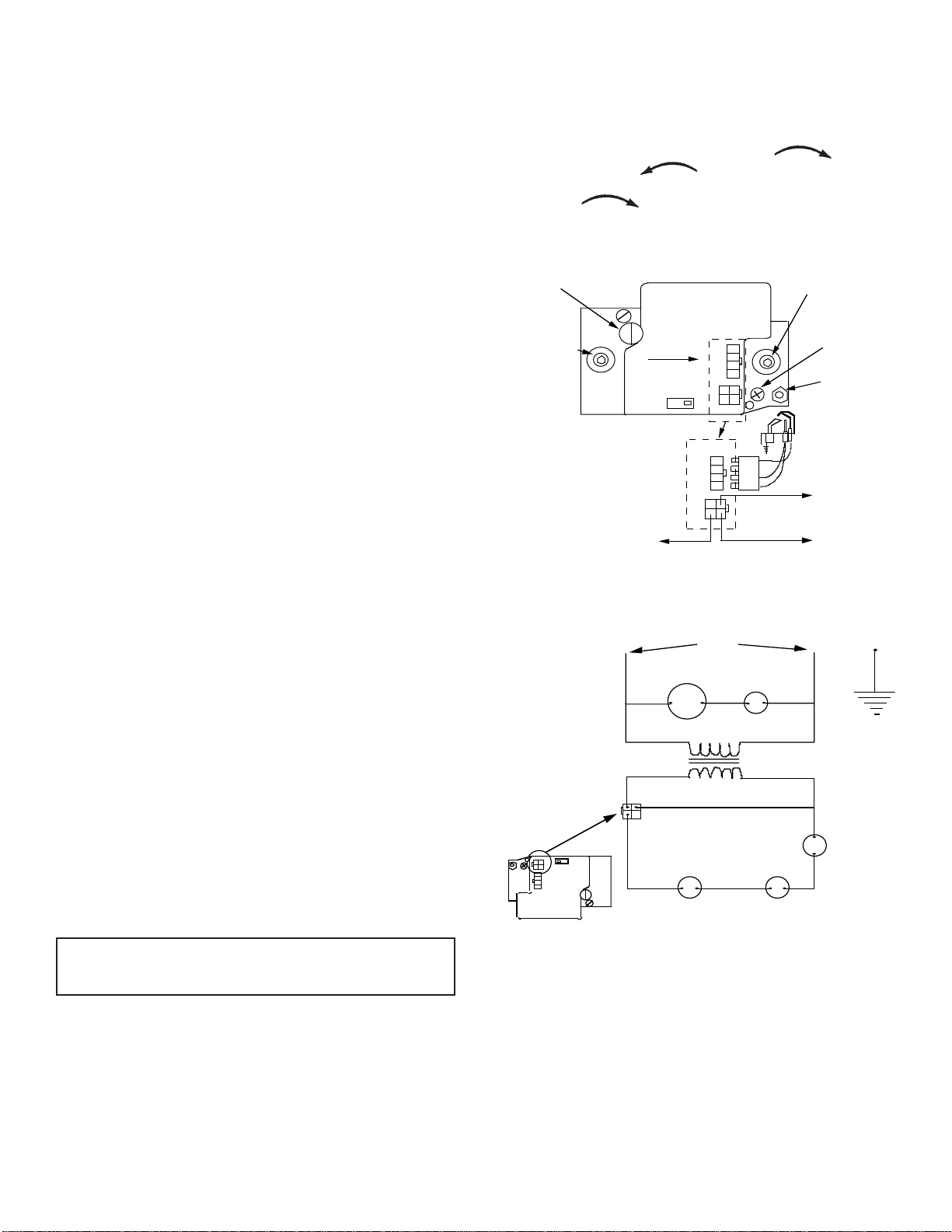
IP-Model Pilot
This heater is using a Honeywell "Smart Valve" system for intermittent
pilot ignition.
On a call for heat by the thermostat this control turns on a 24 volt mini
hot surface ignitor which lights a pilot that in turn lights the main burner.
The gas valve used in this system is a step opening which opens at a
lower pressure for ignition and then steps to a full inlet pressure of 4"
H
O pressure on Natural gas and 10" H20 pressure on LP gas.
2
Pilot Flame Adjustment
The pilot flame should envelop 3/8 to 1/2 inch (10 to 13mm) of the tip
of the flame rod. See Figure 10.
To adjust:
1. Remove the pilot adjustment cover screw.
2. Turn the inner adjustment screw clockwise
or counterclockwise
to increase pilot flame. Pilot adjust-
to decrease
ment is shipped at full flow rate. Turn the inner adjustment screw
clockwise
if the inlet pressure is too high.
3. Replace the cover screw after the adjustment to prevent gas
leakage.
PRESSURE REGULATOR
ADJUSTMENT-UNDER CAP
SCREW
INLET PRESSURE TAP
TO 24 V."HOT" ON TRANSFORMER
VALVE CONTROL
CONNECTOR
HONEYWELL IP
SMART VALVE
GAS FLOW
IGNITOR
ON
OFF
CONTROL
IGNITOR
CONTROL
I P-MODEL GAS VALVE AND WIRING
L2 NEUTRAL
LADDER WIRING DIAGRAM-IP VALVE
120 VAC
MOTOR
120VAC
24 VAC
THERMOSTAT
OUTLET PRESSURE TAP
PILOT ADJUSTMENTUNDER CAP SCREW
IGNITOR-PILOT ASSY.
TO 24 V. THERMOSTAT
TO 24 V. COMMON ON TRANSFORMER
L1 "HOT"
FAN
SWITCH
40 VA TRANSFORMER
VENT SAFETY
LIMIT
PILOT OUTLET
WIRING
LIMIT
CONTROL
Figure 15
Page 10
12427-2-0903
Page 11

STANDING PILOT MODEL
FOR YOUR SAFETY READ BEFORE LIGHTING
WARNING: If you do not follow these instructions exactly, a fire or explosion may result
causing property damage, personal injury or loss of life.
A. This appliance has a pilot which must be lighted by
hand. When lighting the pilot, follow these instructions
exactly.
B. BEFORE LIGHTING smell all around the appliance
area for gas. Be sure to smell next to the floor because
some gas is heavier than air and will settle on the floor.
WHAT TO DO IF YOU SMELL GAS
• Do not try to light any appliance.
• Do not touch any electrical switch;
do not use any phone in your building.
• Immediately call your gas supplier from a neighbor's phone. Follow the gas supplier's instructions.
LIGHTING INSTRUCTIONS
1. STOP! Read the safety information above.
2. Set the thermostat to lowest setting.
3. Turn off all electric power to the appliance.
4. Remove control access panel (lower front panel).
5. Turn gas control knob clockwise to "OFF."
6. Wait ten (10) minutes to clear out any gas. Then smell
for gas, including near the floor. If you smell gas,
STOP! Follow "B" in the safety information above. If
you don't smell gas, go to the next step.
7. Remove the pilot access cover located on the combustion chamber.
8. Find pilot - follow metal tube
from gas control. The pilot is
located between the two burner
tubes behind the pilot access cover.
• If you cannot reach your gas supplier, call the fire
department.
C. Use only your hand to push in or turn the gas control
knob. Never use tools. If the knob will not push in
or turn by hand, don't try to repair it; call a
qualified service technician. Force or attempted
repair may result in a fire or explosion.
D. Do not use this appliance if any part has been under
water. Immediately call a qualified service technician to inspect the appliance and to replace any part
of the control system and any gas control which has
been under water.
9. Turn gas control knob counterclockwise
to "PILOT."
10. Push and hold red reset button down completely and
repeatedly push the ignitor button until the pilot burner
is lit. Pilot may also be lit with a match. Continue to
hold the red reset button down for about one (1)
minute after the pilot is lit. Release button and it will
pop back up. Pilot should remain lit. If it goes out,
repeat steps 5 through 10.
• If button does not pop up when released, stop and
immediately call a qualified service technician or
gas supplier.
• If the pilot will not stay lit after several tries, turn
the gas control knob to "OFF" and call your
service technician or gas supplier.
11. Replace pilot access cover.
12. Turn gas control knob counterclockwise
to "ON."
13. Replace control access panel (lower front panel).
14. Turn on all electric power to the appliance.
15. Set thermostat to desired setting.
TO TURN OFF GAS TO APPLIANCE
1. Set the thermostat to lowest setting.
2. Turn off all electric power to appliance if service is
to be performed .
3. Remove control access panel (lower front panel).
12427-2-0903
4. Push in gas control knob slightly and turn clockwise to "OFF." Do not force.
5. Replace control access panel (lower front panel).
Page 11
Page 12

INTERMITTENT PILOT (IP) MODEL
FOR YOUR SAFETY READ BEFORE OPERATING
WARNING: If you do not follow these instructions exactly, a fire or explosion may result
causing property damage, personal injury or loss of life.
A. This appliance is equipped with an ignition device
which automatically lights the pilot.
Do not try to light the pilot by hand.
B. BEFORE OPERATING smell all around the appliance
area for gas. Be sure to smell next to the floor because
some gas is heavier than air and will settle on the floor.
WHAT TO DO IF YOU SMELL GAS
• Do not try to light any appliance.
• Do not touch any electrical switch;
do not use any phone in your building.
• Immediately call your gas supplier from a neighbor's phone. Follow the gas supplier's instructions.
OPERATING INSTRUCTIONS
1. STOP! Read the safety information above.
2. Set the thermostat to lowest setting.
3. Turn off all electric power to the appliance.
4. This appliance is equipped with an ignition device
which automatically lights the pilot. Do not try to
light the pilot by hand.
• If you cannot reach your gas supplier, call the fire
department.
C. Use only your hand to slide the gas control knob.
Never use tools. Force or attempted repair may
result in a fire or explosion.
D. Do not use this appliance if any part has been under
water. Immediately call a qualified service technician to inspect the appliance and to replace any part
of the control system and any gas control which has
been under water.
5. Remove front panel door.
6. Slide gas control switch to "OFF."
7. Wait ten (10) minutes to clear out any gas. Then
smell for gas, including near the floor. If you smell
gas, STOP! Follow "B" in the safety information
above. If you don't smell gas, go to the next step.
8. Slide gas control switch to "ON".
GAS FLOW
IGNITOR
ON
OFF
CONTROL
GAS VALVE SHOWN IN OFF POSITION
HONEYWELL IP SMART VALVE
TO TURN OFF GAS TO APPLIANCE
1. Set the thermostat to lowest setting.
2. Turn off all electric power to the appliance if service
is to be performed.
3. Remove front panel door.
Page 12
9. Replace front panel door.
10. Turn on all electric power to the appliance.
11. Set thermostat to desired setting.
12. If the appliance will not operate, follow the instructions "TO TURN OFF GAS TO APPLIANCE" and
call your service technician or gas supplier.
4. Slide gas control switch to "OFF."
5. Replace front panel door.
12427-2-0903
Page 13

START
SEQUENCE OF OPERATION
Apply 24 VAC
to Appliance
Thermostat
Calls for Heat
5 Minute Retry
Delay
System Check
Trial for
Ignition
Main Burner
Operation
Flame Signal
Detected
NO
Internal Check
OK
YES
• Pilot Valve Opens
• Ignitor Powered
Pilot Light and Flame is
Sensed During Trial
For Ignition (1)
YES
• Ignitor OFF
• Main Valve Opens
YES
NO
NO
• Pilot Valve Ignition OFF
• Wait for Flame Signal to
Disappear
• Pilot Valve Closes
• Ignition OFF
3 Second Flame
Failure Recycle
Delay
YES
Flame Signal
Lost?
NO
Thermostat Call
for Heat Ends
END
Main Pilot Valves
Close
(1) Ignitor will turn OFF about 30 seconds into the trial for ignition if the pilot flame has not lit. It will turn back ON for the final 30 seeonds
of the 90 second trial for ignition. The pilot valve will be energized during the entire trial for ignition. This is normal operation for this gas
ignition system.
12427-2-0903
Main Pilot
Valves Close
Flame Lost More
Than 5 Times in
One Call for Heat
YES
NO
Page 13
Page 14

IP SYSTEM TROUBLESHOOTING SEQUENCE
START
• Turn OFF Gas Supply
• Disconnect System Control
Harness
• Set Thermostat to Call for
Heat
Check for Proper Voltage at
Control Harness (See Inset A
-Voltage Should be 24V
Between Thermostat and
24V Common, and 24V
Between 24V Common and
24V Hot.)
YES
Plug Harness into SmartValve
Control
W ait for Internal Check Delay
(SV9501)
Igniter Warms UP and
Glows Red
Note: Igniter Will Cycle OFF
and Back ON Once During
the 90 Second Ignition Trial
SmartValve™ System Troubleshooting Sequence
Note: Before Troubleshooting, Become Familiar
with the Sequence of Operation
CHECK
• Line Voltage Power
NO
NO
• Low Voltage Transformer
• Limit Controller
• Thermostat
• Wiring
Unplug Pilot Burner Cable.
Measure Voltage at SmartValue
HSI Element Output (See Inset B)
24V Nominal
YES
Replace Igniter/Flame Rod Assembly
NO
INSET A
24Volt
Thermostat
24
Volts
24 Volt
Common
INSET B
Replace SmartValve Control
Reconnect Pilot Burner Cable
24
Volts
HSI
Terminals
End View
of Control
Harness
Connector
EFT
Output
24 Volt
Hot
YES
• Turn On Gas Supply
• Pilot Burner Lights
YES
Main Valve Opens and
Main Burner Lights
YES
NO
NO
Reconnect Pilot Burner Cable
• Check that Pilot Gas is Flowing
Wait to Assure Pilot Gas Tubing
is Purged.
YES
• Measure Voltage Between 24V Hot
and 24V Common Leads to
SmartValve Control. Must Measure
at Least 19.5 VAC with Igniter
Powered. See Inset A to Identify
Proper Lead. This Check Must be
Done with the SmartValve Control
Connected and Igniter Powered.
YES
Replace Igniter/Flame Rod Assembly
• Check that Pilot Flame Makes Good
Contact with Pilot Burner Flame
Rod
• Check for Good Electrical
Connection Through the Pilot
Tubing
• If Both of the Above are Good,
Replace Igniter/Flame Rod
NO
NO
Replace SmartValve Control
Check Transformer and Line
Volt Supply
System is Okay
Page 14
Cycle Thermostat OFF and Back ON
Main Burner Lights
NO
Replace SmartValve Control
12427-2-0903
Page 15

PLEASE NOTE: When ordering parts, it is very important that part number and description of part coincide.
INDEX PART
NO. NUMBER DESCRIPTION
1 WFA-115 GASKET - HEADER
2 DV-1247 TOP PLATE (USA)
2 15668 TOP PLATE (CANADA)
3 R-3165 DOOR CLIP (2 REQUIRED)
4 DV-1204 CASING SIDE - RIGHT
5 DV-1203 CASING BACK
6 DV-1205 CASING SIDE - LEFT
7 DV-1248 AIR DROP (INCLUDES NO. 54)
8 DV-1231 TURBULATOR (3 REQUIRED)
9 DV-1250 DIVIDER PLATE
10 DV-1234 OUTLET BOX
11 DV-1225 OUTLET BOX COVER
12 R-3177 VENT SAFETY SWITCH
13 R-3161 FAN BLADE
14 R-3166 FAN MOTOR
15 DV-1246 MOTOR MOUNTING BRACKET
16 8720130 BUSHING (5 REQUIRED)
17 8520141 RUBBER GROMMET
(4 REQUIRED)
18 8520142 BRASS BUSHING
(4 REQUIRED)
19 R-3164 DOOR CLIP (2 REQUIRED)
20 DV-1251 INNER SHIELD - RIGHT
(INCLUDES NO. 23)
21 R-6176 FAN CONTROL SWITCH
22 R-3176 LIMIT SWITCH
23 DV-1253 INNER SHIELD COVER PLATE
(2 REQUIRED)
24 DV-1254 INNER SHIELD FRONT (USA)
24 15669 INNER SHIELD FRONT
(CANADA)
25 R-3163 FILTER RETAINER
26 R-3162 FILTER
27 DV-1252 INNER SHIELD -LEFT
(INCLUDES NO. 23)
28 DV-1256 EXCHANGER ASSEMBLY
29 DV-1235 PILOT BRACKET (IP ONLY)
30 R-3232 PILOT - NAT (IP ONLY)
30 R-3233 PILOT - LPG (IP ONLY)
31 742121 ORIFICE - NAT (3 REQUIRED)
31 P-88-60 ORIFICE - LPG (3 REQUIRED)
32 DV-1236 MANIFOLD
33 DV-1258 FRONT PANEL
34 722040 MANIFOLD UNION
35 852051 BUSHING 3/8 x 1/2
36 R-5655 GAS VALVE - LPG (SPP ONLY)
36 R-2148 GAS VALVE - NAT (SPP ONLY)
INDEX PART
NO. NUMBER DESCRIPTION
36 R-3170 GAS VALVE - NAT (IP ONLY)
36 R-3171 GAS VALVE - LPG (IP ONLY)
37 R-2708 PIEZO IGNITOR (SPP ONLY)
38 FF-160 PIEZO BRACKET (SPP ONLY)
39 DV-1318 OBSERVATION HOLE COVER
40 DV-1242 BURNER COMPARTMENT FRONT
41 DV-1237 BURNER COMPARTMENT BODY
42 712045 MANIFOLD GASKET
43 GWT-168 AIR SHUTTER FRONT
44 GWT-169 AIR SHUTTER REAR
45 R-3031 BURNER (3 REQUIRED)
46 DV-1239 BURNER BRACKET
47 UH-452 TRANSFORMER MOUNTING
47 UH-810 TRANSFORMER MOUNTING
48 R-1995 TRANSFORMER (SPP ONLY)
48 8720100 TRANSFORMER (IP ONLY)
49 UH-451 JUNCTION BOX COVER
50 DV-572 JUNCTION BOX
51 DV-1260 COVER PLATE - AIR DROP
52 872056 BUSHING
53 872053 CORD SET
54 8720148 BUSHING
55 DV-1215 BOTTOM PLATE
56 R-3034 PILOT - NAT (SPP ONLY)
56 R-3035 PILOT - LPG (SPP ONLY)
57 GWT-021 PILOT BRACKET (SPP ONLY)
58 R-3180 ELECTRODE AND WIRE
59 R-2256 THERMOCOUPLE -18"
60 R-6389 WALL THERMOSTAT - 24 VOLT
NOT SHOWN DV-1261 PILOT TUBING
NOT SHOWN 742158 PILOT ORIFICE - NAT (SPP ONLY)
NOT SHOWN 742266 PILOT ORIFICE - LPG (SPP ONLY)
NOT SHOWN 742154 PILOT ORIFICE - NAT (IP ONLY)
NOT SHOWN R-3265 PILOT ORIFICE - LPG (IP ONLY)
NOT SHOWN R-3172 WIRE HARNESS (SPP ONLY)
NOT SHOWN R-3173 WIRE HARNESS (IP ONLY)
NOT SHOWN R-1587C VENT SAFETY WIRE ASSEMBLY
PLATE
(SPP ONLY)
(LPG ONLY)
(LPG ONLY)
BRACKET (IP ONLY)
BRACKET (SPP ONLY)
(SPP ONLY)
(SPP ONLY)
USE ONLY MANUFACTURER'S REPLACEMENT PARTS. USE OF ANY OTHER PARTS COULD CAUSE INJURY OR DEATH.
How To Order Repair Parts...
Parts can be ordered only through your service person or dealer. For best results, the service person or dealer should order parts through the distributor.
Parts can be shipped directly to the service person/dealer.
All parts listed in the Parts List have a Part Number. When ordering parts, first obtain the Model Number from the name plate on your equipment. Then
determine the Part Number (not the Index Number) and the Description of each part from the following appropriate illustration and list. Be sure to give
all this information . . .
Furnace Model Number Part Description
Furnace Serial Number Part Number
Type of Gas (Propane or Natural)
Do not order bolts, screws, washers or nuts. They are standard hardware items and can be purchased at any local hardware store.
Shipments contingent upon strikes, fires and all causes beyond our control.
12427-2-0903
Empire Comfort Systems, Inc. Nine Eighteen Freeburg Ave. Belleville, Illinois 62222-0529
Page 15
Page 16

Page 16
12427-2-0903
Page 17

Service Notes
12427-2-0903
Page 17
Page 18

Empire Comfort Systems, Inc.
Nine Eighteen Freeburg Ave.
Belleville, Illinois 62220-2623
PH: 1-618-233-7420
PH: 1-800-851-3153
FAX: 1-618-233-7097
FAX: 1-800-443-8648
E-MAIL: info@empirecomfort.com
WEB SITE: www.empirecomfort.com
Page 18
12427-2-0903
Page 19

INSTRUCTIONS POUR L’INSTALLATION
ET
MANUEL DU PROPRIÉTAIRE
RADIATEUR MURAL À
CIRCULATION FORCÉE ET
AVEC ÉVACUATION
MODÈLE
FAW-40-1SPP
FAW-40-1IP
Installateur: S'il vous plaît, laissez ces instructions
avec le consommateur.
Consommateur: Garder ces instructions pour
référence ultérieure.
AVERTISSEMENT:
Si l’installation, l’usage et l’entretien de ce
produit ne sont pas faits selon les instructions
du fabricant, ce produit peut vous exposer à
des matières contenues dans le carburant ou
provenant de la combustion du carburant
lesquelles peuvent causer la mort ou de
sérieuses maladies.
DATE D’ENTRÉE EN VIGUEUR
SEPTEMBRE 2003
AVERTISSEMENT:
Si les informations dans ce manuel ne sont pas
exactement suivies, un feu ou une explosion
peut en résulter causant des dommages à la
propriété, des blessures corporelles ou la mort.
— Ne pas entreposer ou employer de la gazoline ou
d’autres vapeurs ou liquides inflammables
àproximité de cet appareil ou tout autre appareil.
— QUE FAIRE SI VOUS SENTEZ LE GAZ.
• N’essayer pas d’allumer un appareil.
• Ne toucher pas un interrupteur électrique;
n’employer pas un téléphone dans le bâtiment.
• Appeler immédiatement votre fournisseur de
gaz en employant le téléphone de votre voisin.
Suivre les instructions du fournisseur de gaz.
• Si vous ne pouvez pas contacter votre
fournisseur de gaz, appeler le poste de
pompiers.
— L’installation et le service doivent être exécutés
par un installateur qualifié, une agence d’entretien
ou un fournisseur de gaz.
12427(F)-2-0903
Page 1
Page 20

Introduction
Toujours consulter le département de construction de votre région en ce
qui regarde les règlements, les codes ou les ordonnances qui s’appliquent
à l’installation d’un radiateur mural avec évacuation.
Instructions pour l'Installateur
1. Après l’installation, l’installateur doit laisser le manuel d’instructions
au propriétaire.
2. L’installateur doit demander au propriétaire de compléter et poster
la carte de guarantie de l’unité de chauffage.
3. L’installateur doit expliquer au propriétaire la mise en marche et le
fonctionnement du radiateur et du thermostat.
AVERTISSEMENT:
Tout changement fait à ce radiateur ou à ces commandes peut
être dangereux. Ceci est un appareil de chauffage et si un
panneau, une porte ou un dispositif protecteur est enlevé pour
l’entretien de cet appareil, il doit être replacé avant de remettre
en marche.
Informations Générales
Cette série est un modèle conformément certifié avec l'American National Standard / CSA Standard Z21.86 et CSA 2.32 par Canadian
Standards Association comme étant un radiateur mural à circulation
forcée et avec évacuation, devant être installé selon ces instructions.
Tout changement du modèle d’origine, installé autrement que
décrit dans ces instructions ou fonctionnant avec un genre de gaz qui
n’est pas indiqué sur la plaque d’identification, est la responsabilité
de la personne et de la compagnie faisant ce changement.
Important
Toute la correspondance doit mentionner le numéro complet du modèle
et de la série et le genre de gaz.
AVIS: Pendant le premier allumage de cette unité, la peinture cuira et
de la fumée se produira. Pour prévenir les détecteurs de fumée de se
déclencher, bien ventiler l’appartement dans lequel l’unité est installée.
Installation sur un Tapis ou Tuile
Si cet appareil est installé directement sur un tapis, tuiles ou tout genre
de matériel combustible autre qu’un plancher de bois, cet appareil doit
être installé sur un panneau de métal ou de bois, celui-ci ayant la largeur
et la profondeur de l’appareil.
La base que nous décrivons ci-dessus ne signifie pas le genre de base
contre le feu comme il est utilisé pour les poêles à bois. La protection
est pour les tapis extrêmement épais et les tuiles de couleur qui pourraient
se décolorer.
Installation dans les Garages Residentiels
Tous les équipements dans les garages résidentiels employant du gaz,
doivent être installés de façon à ce que les brûleurs et les appareils pour
allumer les brûleurs doivent être situés à au moins 18" (45.7cm) au
dessus du plancher.
Tous ces équipements doivent être situés ou protégés de façon à ce qu’un
véhicule en se déplaçant ne puisse les endommager.
SPÉCIFICATIONS
Modèle FAW-40SPP FAW-40IP
Puissance d’entrée BTUH(KW/H) 40,000 (11.7) 40,000 (11.7)
Hauteur 72 1/2" (184.2cm) 72 1/2" (184.2cm)
Largeur 14 1/8" (35.9m) 14 1/8" (35.9m)
Profondeur 10 3/8" (26.4mm) 10 3/8" (26.4mm)
Arrivée de gaz(tuyau) 1/2" (1.27cm) 1/2" (1.27cm)
Collet de l’évent ovale de type B 4" (10.2cm) 4" (10.2cm)
CFM 275 275
ACCESSOIRES
Registre, sortie de côté, registre fixe SOR-1
Sortie de côté, extension maximum de 10" SOK-1
(254mm), registre fixe
Sortie arrière, extension maximum de 10" ROK-1
(254mm), registre ajustable.
Enceinte de l’évent, 24" (61cm) [pour une FVE-24
chambre jusqu’à 96 1/2" (245cm) de hauteur]
Enceinte de l’évent, 34" (86cm) [pour une FVE-34
chambre jusqu’à 106 1/2" (270.5cm) de hauteur]
Enceinte de l’évent, 46" (117cm) [pour une FVE-46
chambre jusqu’à 118 1/2" (301cm) de hauteur]
Assemblage de l’adaptateur de la bouche DV-648
ovale à rond de 4" (102mm)
CECI EST UN APPAREIL DE CHAUFFAGE
NE PAS FAIRE FONCTIONNER CET APPAREIL SANS QUE LE PANNEAU DU DEVANT SOIT INSTALLÉ.
• A cause des hautes températures, cet appareil doit être situé
dans un endroit non achalandé et loin des meubles et des
rideaux.
• Les enfants et les adultes doivent être avisés des dangers des
parois très chaudes et doivent rester loin pour éviter les brûlures
ou l’allumage des vêtements.
• Les petits enfants doivent être surveillés étroitement lorsqu’ils
sont dans le même appartement que l’appareil.
• Les vêtements ou d’autres matériaux inflammables ne doivent
pas être placés sur ou près de l’appareil.
• Tout écran de sûreté qui est enlevé lors de la réparation d’un
appareil, doit être replacé avant de remettre en marche cet
appareil.
• Garder propre le brûleur et le compartiment de contrôle.
• L’installation et la réparation doivent être faites par une
PERSONNE QUALIFIÉE. L’appareil doit être inspecté avant
l’usage et au moins une fois par année, par une personne
qualifiée. S’il y a un excès de poussière venant du tapis, de la
litterie, etc..., de fréquents nettoyages seront requis. Il est
impératif que les compartiments de commandes, les brûleurs et
les passages de circulation d’air de l’appareil soient gardés
propres.
• Ne rien mettre autour du radiateur qui pourrait obstruer le
débit de combustion et la ventilation d’air.
• Les matériaux combustibles, la gazoline ou les vapeurs et
liquides inflammables ne doivent jamais être dans le même
endroit que le radiateur.
• Examiner périodiquement le système de ventilation et remplacer
les pièces défectueuses.
• Faire périodiquement une inspection visuelle de la veilleuse et
des brûleurs. Nettoyer et remplacer les pièces défectueuses.
AVERTISSEMENT: Le couvercle pour l’accès à la veilleuse
doit toujours être gardé hermétiquement fermé lors du
fonctionnement.
• Ne pas utiliser ce radiateur s’il y a une pièce qui a été en contact
avec l’eau. Appeler immédiatement un technicien qualifié pour
inspecter le radiateur et remplacer toute pièce du système de
commande et les commandes de gaz qui ont été en contact avec
l’eau.
• Ce radiateur ne doit pas être branché à une cheminée servant
à un autre appareil brûlant un combustible solide.
IMPORTANT: Ce radiateur a un filtre permanent que
vous pouvez laver au moins une fois par année avant la
saison du chauffage. Pour des endroits souillés ou très
achalandés, des nettoyages plus fréquents seront requis.
Page 2
12427(F)-2-0903
Page 21

INFORMATION DE SÉCURITÉ POUR LES UTILISATEURS DE PROPANE
Le propane est un gaz inflammable qui peut causer des feux et
des explosions. Dans son état naturel, le propane est inodore
et sans couleur. Peut-être que vous ne connaissez pas toutes les
précautions décrites ci-dessous? Elles peuvent vous protéger
ainsi que votre famille contre un accident. Lisez-les
attentivement dès maintenant, puis réexaminez les, point par
AVERTISSEMENT À PROPOS DE L’ODEUR DU PROPANE
Si une fuite de gaz survient, vous devriez sentir le gaz parce qu’il y a une odeur incorporée au propane.
C’est le signal que vous devez agir immédiatement.
• N’utiliser pas les interrupteurs électriques, n’allumer pas des
allumettes ou n’utiliser pas le téléphone. Ne rien faire qui pourrait
enflammer le gaz.
• Évacuer tout le monde du bâtiment, des véhicules et des lieux. Faire
ceci immédiatement.
• Fermer toutes les soupapes d’approvisionnement des réservoirs et
des bouteilles de gaz.
• Le propane est plus pesant que l’air et peut s’accumuler dans des
endroits bas comme les soubassements. Lorsque vous avez des
raisons de suspecter une fuite de gaz, n’allez pas dans les
soubassements ou les endroits bas. Attendez que les pompiers vous
AUCUNE ODEUR DÉCELÉE - FAIBLE ODEUR
Il y a des personnes qui ne peuvent pas sentir très bien. Il y a des
personnes qui ne peuvent pas sentir l’odeur chimique mis dans le
gaz. Vous devez vérifier si vous pouvez sentir cette odeur. Fumer peut
décroître votre capacité de sentir. Sentir une odeur pour un certain
temps, peut affecter votre sensibilité ou votre capacité de déceler cette
odeur. Quelquefois d’autres odeurs, dans le même endroit, peuvent
masquer l’odeur du gaz. Il y a des personnes qui ne peuvent pas sentir
l’odeur du gaz ou que leur attention est sur quelque chose d’autre.
Penser à sentir l’odeur du gaz peut faciliter la capacité de sentir.
L’odeur dans le propane est sans couleur et peut s’affaiblir selon
certaines circonstances. Par exemple, s’il y a une fuite souterraine, le
mouvement du gaz à travers le sol peut filtrer l’odeur. Aussi, l’odeur
dans le propane peut être exposée à l’oxydation. Cet affaiblissement
point avec les membres de votre famille. Un jour, lorsqu’il n’y
aura pas une minute à perdre, la sécurité de chacun dépendra
de votre savoir-faire. Si après avoir lu les informations
suivantes, vous pensez avoir besoin de plus amples informations, s’il vous plaît contactez votre fournisseur de gaz.
assurent de la sûreté de ces endroits avant d’y aller.
• Utiliser le téléphone de votre voisin et appeler les pompiers et une
personne entraînée avec le propane.
• Ne pas ouvrir les soupapes d’approvisionnement de gaz même si
vous ne le sentez plus. Ne retourner pas dans le bâtiment, sur les
véhicules ou sur les lieux.
• Finalement, laisser la personne qualifiée et les pompiers vérifier les
fuites de gaz. Laisser-les aérer les lieux avant d’y retourner. Les
personnes entraînées avec le propane devront réparer la fuite,
vérifier et réallumer l’appareil au gaz, pour vous.
peut survenir s’il y a de la rouille à l’intérieur des réservoirs ou dans les
tuyaux de fer pour le gaz.
L’odeur de la fuite de gaz peut être adsorbée ou absorbée sur ou dans
les murs, maçonnerie et d’autres matériaux et tissus dans une chambre.
Ceci enlèvera une quantité de l’odeur du gaz, affaiblissant l’intensité
de la senteur.
Le propane peut stratifier dans un endroit fermé et l’intensité de l’odeur
peut varier à différents niveaux. Puisque le propane est plus pesant que
l’air, l’odeur peut être plus prononcée à un bas niveau. Toujours être
sensible à la moindre odeur de gaz. Si vous décelez une odeur, réagissez
comme si vous aviez une sérieuse fuite. Passez à l’action immédiatement
en suivant les informations précédentes.
QUELQUES POINTS À RETENIR
• Apprendre à reconnaître l’odeur du propane. Votre
distributeur de propane peut vous donner un échantillon que
vous grattez et sentez. Utilisez-le pour savoir reconnaître l’odeur
du propane. Si vous pensez que votre gaz propane a une faible
ou anormale odeur, appelez votre distributeur.
• Si vous n’êtes pas qualifié, n’allumer pas la veilleuse, n’effectuer
pas l’entretien ou n’ajuster pas les appareils fonctionnant au
propane. Si vous êtes qualifié, soyez conscient de l’odeur du
propane avant et pendant que vous allumez la veilleuse, effectuez
l’entretien ou faites les ajustements.
• Quelquefois un soubassement ou une maison fermée a une
senteur de moisi qui peut dissimuler l’odeur de propane.
N’essayez pas d’allumer des veilleuses, d’effectuer l’entretien
ou de faire des ajustements dans des endroits où les conditions
sont de telle sorte que vous ne pouvez pas déceler l’odeur du
propane en cas de fuite.
• L’affaiblissement d’odeur, attribuable à l’oxydation par la rouille
ou l’adsortion sur les parois des nouveaux réservoirs et bouteilles,
est possible. Par conséquent, les personnes doivent être
particulièrement prudentes lorsque de nouveaux réservoirs ou
bouteilles sont mis en service. L’affaiblissement d’odeur peut
se produire dans les nouveaux réservoirs ou dans les vieux
réservoirs qui sont réinstallés, s’ils sont remplis et inutilisés
12427(F)-2-0903
pour une longue période de temps. La formation de rouille à
l’intérieur des bouteilles et des réservoirs qui ne sont pas
utilisés pour une longue période de temps, peut provoquer un
affaiblissement de l’odeur. Si vous pensez que de telles conditions existent, un test de senteur de gaz est recommandé
périodiquement. Si vous avez des questions à propos de
l’odeur du gaz, appelez votre distributeur de propane. En
toute circonstance, un test de senteur périodique du gaz
propane est une mesure de prudence.
• Si en aucun temps vous ne sentez pas l’odeur du propane et que
vous devriez, assumez que vous avez une fuite. Agissez
immédiatement selon les recommandations ci-dessus, décrivant
les actions à suivre en cas de décèlement de gaz propane.
• Si vous découvrez que le réservoir est complètement vide de
gaz (le réservoir n’a aucune pression de vapeur), fermez la
soupape du réservoir immédiatement. Si la soupape du réservoir
reste ouverte, le réservoir peut aspirer de l’air par les ouvertures,
par exemple les orifices de la veilleuse. Si ceci survient,
l’intérieur peut subir une additionnelle formation de rouille. Si
la soupape est restée ouverte, considérez le contenant comme
étant un nouveau réservoir. Soyez toujours certain que le
réservoir est sous pression de vapeur; fermez la soupape du
réservoir avant qu’il ne soit complètement vide et faites le
remplir.
Page 3
Page 22

Air de Ventilation et de Combustion
ATTENTION: Danger pour des dommages à la propriété, des
blessures ou la mort, ce radiateur et d’autre sorte d’appareil au gaz
doivent avoir assez d’air frais pour permettre une bonne combustion
et une bonne ventilation des gaz d’échappement. La plupart des
maisons exigera que l’air extérieur soit accessible. Ne tirez pas de
l’air venant d’un environnement malsain comme un atelier ou une
chambre à lavage.
Les exigences pour pourvoir pour l’air de combustion et de ventilation
sont inscrites dans les Codes du National Fuel Gas NFPA 54/ANSI
Z223.1 (au Canada - CAN/CGA B149).
Note: Les exigences d’air pour le fonctionnement des ventilateurs
soufflants, les systèmes de ventilation pour les cuisines, les sécheuses,
foyer et tout autre installation de combustion ou de ventilation qui sont
utilisés dans le même espace, doivent être mis en considération lorsque
vous déterminez les exigences pour l’air de combustion.
Ouvertures et Conduits pour l’Air de Ventilation
En déterminant l’espace libre que vous aurez besoin, vous devrez prendre
en considération les conséquences d’obstruction des volets, grilles ou
moustiquaires qui protègent les ouvertures.
— Si un moustiquaire est utilisé pour recouvrir les ouvertures, les mailles
ne doivent pas être plus petites que 6mm.
— Utilisez l’espace libre du volet ou de la grille pour déterminer la
grandeur de l’ouverture exigée pour fournir l’espace libre spécifié. Si
vous ne connaissez pas l’espace libre, mettez un espace libre de 20%
pour le bois et un espace libre de 60% pour un volet ou une grille en
métal.
— Les conduits doivent avoir les mêmes espaces représentés que les
espaces libres des ouvertures à lesquelles ils sont branchées.
— Les dimensions minimum pour les conduits d’air ne doivent pas être
moins que 3" (76mm).
Installation dans un Espace Ouvert
Un espace ouvert est un espace incluant toutes les pièces qui ne sont pas
séparées par des portes et avec un volume plus grand que 50 pied cube par
1,000 Btuh d’un débit d’entrée combiné pour tous les appareils lesquels
tirent de l’air de combustion de ces pièces. Par exemple, un espace
incluant un chauffe-eau évalué à une entrée de 40,000 Btuh et un radiateur
évalué à 40,000 Btuh exigera un volume de 4,000 pied cube (50 x (40+40)
= 4,000) pour être considéré comme un espace ouvert. Si l’espace a un
plafond de 8' (244 cm), la surface de plancher de l’espace doit être de 500
pied cube. En général, particulièrement dans les vieilles maisons, un
radiateur qui sera installé dans un espace ouvert, n’exigera pas d’air
extérieur pour la combustion. Cependant, dans une maison récemment
construite dont l’isolation est très bonne, l’air extérieur peut être nécessaire
pour assurer une bonne combustion.
Installation dans un Espace Restreint
Un espace restreint est un espace avec un volume plus petit que 50 pied
cube par 1,000 Btuh d’un débit d’entrée combiné pour tous les appareils
lesquels tirent de l’air de combustion de ces pièces. Des petits espaces
comme des salles d’exercice sont des espaces restreints. Les radiateurs
qui sont installés dans des espaces restreints lesquels alimentent d’air
chaud des espaces à l’extérieur de ceux-ci, doivent tirer l’air de retour à
l’extérieur de l’espace et à travers des conduits d’air de retour qui seront
très étanches. Un espace restreint doit avoir deux ouvertures dans cet
espace pour l’air de combustion. Une ouverture ne doit pas être à plus de
12" (30.5 cm) du plafond et l’autre ne doit pas être à plus de 12" (30.5 cm)
du plancher. La grandeur exigée pour ces ouvertures est déterminée selon
que vous utilisez l’air intérieur ou extérieur pour supporter la combustion,
la méthode par laquelle l’air est acheminé à l’espace (conduit vertical ou
horizontal) et par le débit d’entrée total de tous les appareils dans cet
espace. Voir Figure 1.
Air Total Venant de l’Intérieur - Espace Restreint
Si l’air de combustion vient de l’espace chauffé, chacune des deux
ouvertures doit avoir un espace libre d’au moins un pouce carré par 1,000
Btuh de débit d’entrée de tous les appareils dans l’espace restreint, mais
pas moins que 100"
Par exemple: pour un radiateur de 40,000 Btuh, seulement dans un espace
restreint, chaque ouverture doit avoir un espace libre de 100"
2
(645cm2) d’espace libre.
2
(645cm2).
ATTENTION: L’air de combustion ne doit pas provenir d’un espace
chauffé lequel inclus des ventilateurs soufflants, foyers ou d’autres
appareils qui peuvent produire une pression négative dans l’espace.
RADIATEUR
furnace
confined
ESPACE
space
RESTREINT
OUVERTURE
opening
Figure 1
Air Extérieur
L’entrée et la sortie d’air peuvent être apportées dans l’espace restreint par
des ouvertures dans un grenier ventilé et une cave ventilée.
VOLET DE VENTILATION DU GRENIER
attic ventilation louvers
SORTIE D’AIR
furnace
RADIATEUR
crawl space ventilation louvers
VOLETS DE VENTILATION DE LA CAVE
outlet air
ENTRÉE D’AIR
inlet air
Figure 2
Espace Restreint
Air Extérieur Utilisant des Conduits Verticaux ou Horizontaux
Si l’air de combustion est pris à l’extérieur par des conduits verticaux, les
ouvertures et les conduits doivent avoir un espace libre minimum de 1"
(6.5cm2) par 4,000 Btuh d’entrée totale pour l’appareil. Dans les installations prenant l’air de combustion d’un grenier ventilé, les deux conduits
d’air doivent s’allongé au-dessus de l’isolation du grenier.
SORTIE D’AIR
outlet air
furnace
RADIATEUR
ENTRÉE D’AIR VERTICALE FINIT 1' (30.5cm) AU-DESSUS DU PLANCHER
inlet air ends one foot above floor
furnace
RADIATEUR
vertical
CONDUIT POUR
LA SORTIE
D’AIR
CONDUIT POUR
L’ENTRÉE D’AIR
horizontal
outlet air duct
inlet air duct
2
Page 4
Figure 3
12427(F)-2-0903
Page 23

Si l’air de combustion est pris à l’extérieur par des conduits horizontaux,
les ouvertures et les conduits doivent avoir un espace libre minimum de
2
(6.5cm2) par 2,000 Btuh d’entrée totale pour l’appareil.
1"
Agence d’Installation Qualifiée
L’installation et le remplacement des tuyaux à gaz, des équipements ou
accessoires, la réparation et l’entretien de l’équipement doivent être faits
seulement par une agence qualifiée. Le terme “agence qualifiée” signifie
tout individu, firme, corporation ou compagnie qui est, en personne ou par
un représentant, engagé et responsable de: (a) l’installation ou le
remplacement des tuyaux à gaz, ou (b) la connexion, l’installation, la
réparation ou l’entretien de l’équipement, qui possède l’expérience
nécessaire en ce genre de travail, est familier avec les précautions requises
et s’est conformé à toutes les exigences de l’autorité ayant juridiction.
L’installation doit être conforme aux codes locaux. Dans l’absence de
codes locaux, l’installation doit se conformer avec National Fuel Gas
Code, ANSI Z223.1/NFPA 54* Natural and Propane Installation Code,
CSA 1-B149.1.
* Disponible chez American National Standards Institute, Inc., 11 West 42nd St., New York, N.Y. 10036.
Espaces Libres
1. En choisissant un emplacement, il est nécessaire de fournir l’espace
libre adéquat pour l’accès à l’installation et à l’entretien.
2. Le FAW-40 peut être attaché au mur ou encastré dans le mur jusqu’à
9 1/2" (24.1cm ) de profondeur. Note: Ne placez pas le collecteur ou
matériel combustible sur le dessus de l’unité lorsqu’il est installé
dans le mur. Maintenir un espace minimum de 3/4" (19mm) audessus du radiateur.
3. L’espace libre entre les côtés et le dessus du radiateur au mur dans
lequel le radiateur est encastré est de 0.
4. Lorsque vous utilisez les registres se dégageant sur les côtés, SOR-1
ou SOK-1, le radiateur ne peut pas être encastré dans le mur.
5. L’espace libre aux murs de côté ou aux matériaux combustibles est de
4" (10.2cm).
6. L’espace libre au plafond est de 4" (10.2cm).
7. L’espace libre au plancher et au mur arrière est de (0) zéro cm.
8. Lorsque le registre avec sortie sur le côté est utilisé, SOR-1, l’espace
libre requis entre le radiateur et les murs de côté ou les matériaux
combustibles est de 18" (46cm).
Avant l’Installation, Prendre en Considération les Évents Suivants
1. Une cheminée pour un genre résidentiel ou pour une installation
utilisant un gaz à basse température doit s’allonger d’au moins 3'
(91.4cm) au-dessus du point le plus haut où elle passe à travers le toit
du bâtiment et d’au moins 2' (61cm) au-dessus de n’importe quelle
section du bâtiment dans une distance horizontale de 10' (3m).
2. Ce radiateur ne doit pas être branché à une cheminée servant à un autre
appareil brûlant un combustible solide.
3. Les tuyaux de métal à simple paroi non-isolée ne doivent pas être
utilisés dans les endroits à climat froid pour une installation
utilisant un gaz d’échappement.
4. Attention! Ce radiateur mural à circulation forcée est muni d’un
interrupteur de sûreté de l’évent. Dans le cas d’un écoulement des
produits d’échappement dû à un mauvais fonctionnement de l’évent,
l’interrupteur de sûreté de l’évent s’ouvre et ceci aura pour résultat de
“fermer” les brûleurs principaux.
L’évacuation du modèle FAW-40 peut se faire comme il est représenté
dans la Figure 4. La terminaison du capuchon d’évent doit être à au moins
12' (3.7m) au-dessus du plancher et doit s’évacuer à l’extérieur. Les
entretoises fixes du tuyau d’évent B-1 gardent l’espace libre aux constructions combustibles à 1" (25mm). L’installation doit être conforme aux
codes locaux.
A. Rond de 4" (102mm) (toutes les pièces peuvent être achetées
localement, excepté l’item 2)
1. Tuyau rond de type B-1.
2. Pièce no. DV-648, l’assemblage de l’adaptateur de la bouche ovale
à rond de 4" (102mm).
3. Les évents à gaz de type B-1 pour un étage exige une plaque de base
et une paire d’entretoises pour la plaque du plafond.
4. Les évents à gaz de type B-1 pour plus d’un étage exige une plaque
de base, une paire d’entretoises pour la plaque du plafond, au plafond
du premier étage et une paire d’entretoises pour l’arrêt de feu à
chaque niveau de plafond successif.
12427(F)-2-0903
ROND 4"
4" ROUND
(102 mm)
VENT
ENCEINTE DE
ENCLOSURE
MUR
WALL
ADAPTATEUR
ADAPTER
PLAQUE DE BASE
BASEPLATE
L’ÉVENT
A.
CÔTÉ
SIDE
OVALE B-1 4"
4" B-1 OVAL
(102 mm)
SUPPORT
BRACKET
PLAQUE DE BASE
BASEPLATE
FRONT
DEVANT
B.
OVALE B-1 4"
4" B-1 OVAL
(102 mm)
4" 45 DEG.
COUDES OVALES
OVAL ELBOWS
45˚ 4" (102 mm)
C.
C.
B. Ovale de 4" (102mm) (toutes les pièces peuvent être achetées
localement)
1. Tuyau ovale de type B-1 ou tuyau d’évacuation B-W.
2. Les évents à gaz de type B-1 ou (B-W) pour un étage exige une
plaque de base et une paire d’entretoises pour la plaque du plafond.
3. Les évents à gaz de type B-1 ou (B-W) pour plus d’un étage exige une
plaque de base, une paire d’entretoises pour la plaque du plafond, au
plafond du premier étage et une paire d’entretoises pour l’arrêt de feu
à chaque niveau de plafond successif.
C. Ovale dans le mur, 4" (10.2cm) (toutes les pièces peuvent être
achetées localement).
1. Tuyau ovale de type B-1 ou tuyau d’évacuation B-W.
2. Coudes ovales de type B-1 ou coudes ovales B-W.
3. Les évents à gaz de type B-1 ou (B-W) pour un étage exige une plaque
de base et une paire d’entretoises pour la plaque du plafond.
SPACER
ENTRETOISE
BASEPLATE
PLAQUE DE BASE
OVALE B-1 4"
4" B-1 OVAL
(102 mm)
SPACER
ENTRETOISE
PLAQUE DE BASE
BASEPLATE
Figure 4
Page 5
Page 24

4. Les évents à gaz de type B-1 ou (B-W) pour plus d’un étage exige une
plaque de base, une paire d’entretoises pour la plaque du plafond, au
plafond du premier étage et une paire d’entretoises pour l’arrêt de feu
à chaque niveau de plafond successif.
L’espace entre les montants autour des évents à gaz doit être sans
obstruction et sans papier de construction
Pour installer le SOK-1, s’il vous plaît utilisé les étapes 1 jusqu’à 5 dans
les instructions du SOR-1 pour les radiateurs FAW-40. Maintenant,
utiliser les étapes suivantes pour compléter l’installation du SOK-1.
1. En utilisant les trémies intérieurs et extérieurs comme guide pour les
trous, marquer et percer (4) trous de 1/8" (3mm) de diamètre dans la
paroi intérieure et (4) trous de 1/8" (3mm) de diamètre sur le côté du
radiateur.
2. Situer et couper une ouverture carrée de 6 3/4" (171mm) à travers le
mur.
3. Fixer le radiateur au mur (voir Fixer le Radiateur au Mur).
4. Avec le radiateur en place, après avoir vérifié l’alignement de
l’ouverture de sortie sur le côté dans le mur et le radiateur , placer la
plaque murale de sortie de côté de 9 3/8" x 9 3/8" (238mm x 238mm)
par dessus le trémie extérieur. Passer le trémie extérieur à travers le
mur et attacher la plaque murale de côté au mur du côté du radiateur
avec (2) vis #10 x 1 1/2" (38mm). Les vis sont fournies.
5. Attacher le trémie extérieur au côté du radiateur avec (4) vis #8 x 1/4"
(6mm). Les vis sont fournies.
6. Positionner et attacher le trémie intérieur à la paroi intérieure avec (4)
vis #8 x 1/4" (6mm). Les vis sont fournies.
7. Placer le registre dans l’ouverture carrée de 6 3/4" (171mm) avec ses
volets dans la position désirée pour la sortie d’air et marquer les trous
de montage en utilisant le registre comme guide.
8. Percer (2) trous de 1/8" (3mm) de diamètre dans le mur et attacher le
registre avec (2) vis #10 x 1 1/2" (38mm. Les vis sont fournies.
9. L’installation du SOK-1 est complétée.
4" MINIMUM TO COMBUSTIBLE
WALL OR SURFACE
4" MINIMUM TO COMBUSTIBLE
WALL OR SURFACE
Page 6
WALL
18" MIN. CLEARANCE TO
WALL OR COMBUSTIBLE
SURFACE USING MODEL
SOR-1 SIDE REGISTER.
CLEARANCE FOR SIDE OUTLET KITS AND REAR REGISTER
KIT TO ADJACENT WALL
TYPE B-1 OR
B-W OVAL
VENT PIPE
WHEN SIDE REGISTERS ARE
NOT USED UNIT MAY BE RECESSED
UP TO 9 1/2"
UNIT CANNOT BE RECESSED
WHEN SIDE REGISTERS ARE
USED.
5 1/2"
5 1/2"
12" 12"
REAR REGISTER OPENING
IN OUTER CABINET
6 1/4"
10 1/4"
Figure 6
Installation d’une Sortie Arrière Optionnelle
L’assemblage de sortie arrière, l’assemblage du trémie de 10" (254mm)
avec registre ROK-1, pour l’évacuation d’air chaud dans une pièce
voisine.
Attention! Avant de fixer le radiateur au mur, vous devez couper
l’ouverture dans le mur pour la sortie arrière, en plus d’enlever les entrées
défonçables de la paroi intérieure et extérieure du radiateur.
1. Les mesures pour l’ouverture dans le mur de la sortie arrière sont les
suivantes.
A. Du plancher au bas de l’ouverture murale, la distance est 10-11/16"
(271mm).
B. Du bas de l’ouverture murale au haut de l’ouverture murale, la
distance est 8-1/2" (216mm).
C. La largeur de l’ouverture murale est 12-1/8" (308mm).
2. Tracer une ligne entre les quatre fossettes de la paroi extérieure
12427(F)-2-0903
Page 25

arrière pour former un carré. Percer un trou pilote à l’intérieur du
carré que vous avez tracé sur la paroi extérieure arrière. Enlever la
feuille de métal à l’intérieur du carré que vous avez tracé, avec des
ciseaux à métal ou un outil comparable.
3. Enlever les (4) vis # 8 x 3/8" (9mm) qui attachent la plaque de
fermeture de la paroi intérieure, à la paroi intérieure.
4. Insérer l’écran protecteur à travers la paroi extérieure arrière et
l’arrière de la paroi intérieure. L’écran protecteur sera devant la
paroi intérieure arrière et derrière les tuyaux de la chambre de
combustion. Aligner les trous libres de l’écran protecteur avec les
trous de vis de la paroi intérieure arrière. Attacher l’écran protecteur
à la paroi intérieure arrière avec (2) vis # 8 x 3/8" (9mm). Les vis sont
fournies. Attention: Les (2) vis # 8 x 3/8" (9mm) doivent être
insérées àpartir de l’avant du radiateur.
5. Fixer le radiateur au mur (Référer aux Instructions pour l’Installation
et Manuel du Propriétaire).
6. Aligner les trous libres du trémie de 8" x 12" (203mm x 305mm) avec
les trous de vis de la paroi extérieure arrière et marquer le trémie pour
qu’il soit au niveau avec la sx 254mm avec les trous de vis de la paroi
intérieure arrière et marquer le conduit pour qu’il soit 57mm plus
petit que le trémie de 8" x 12" (203mm x 305mm). Enlever le conduit
et couper à la longueur convenable.
7. Fixer le trémie de 8" x 12" (203mm x 305mm) à la paroi extérieure
arrière avec (6) vis #8 x 3/8" (9mm). Les vis sont fournies.
8. Aligner les trous libres du conduit le 6" x 10" (152m x 254mm) avec
les trous de vis de la paroi intérieure arrière et marquer le conduit
pour qu'il soit 2 1/4" (57mm) plus petit que le trémie de 8" x 12"
(203mm x 305mm). Enlever le conduit et couper à la longueur
convenable.
9. Fixer le conduit de 6" x 10" (152m x 254mm) à la paroi intérieure
arrière en utilisant les 4 vis # 8 x 3/8" (9mm) que vous avez enlevées
à l’étape 3, 2 en haut et 2 en bas. Les vis sont fournies.
10. Insérer le registre arrière dans le trémie de 8" x 12" (203mm x
305mm). Fixer le registre arrière au mur avec (2) vis #10 x 1"
(25mm). Les vis sont fournies.
11. L’installation du ROK-1 est complétée.
Emplacement du Radiateur Sur le Mur
Le radiateur doit être situé sur un mur. Le radiateur a une largeur de 14 1/8"
(35.9cm) et peut être encastré dans le mur avec l’espace standard des
montants.
Un guide est fourni dans l’emballage du radiateur pour vous aider à
localiser la connexion pour la ligne de gaz. Aussi, référer à la Figure 7
pour positionner le radiateur sur le mur et pour localiser la connexion
pour la ligne de gaz.
Emplacement de l'Alimentation de Gaz
La ligne de gaz peut entrer dans l’appareil soit en venant du plancher ou
du mur extérieur. L’ouverture pour la ligne de gaz doit être faite à ce
moment. L’emplacement de l’ouverture sera déterminé par la position
des solives du plancher et par la valve et le raccord utilisé lors de
l’entretien. Voir Figure 7.
Emplacement de l'Alimentation Électrique
Sur le bas des panneaux des côtés gauche et droit, il y a une entrée
défonçable de 7/8" (22mm) de diamètre. L’assemblage de la fiche à trois
broches (prise de terre) est situé dans le compartiment des contrôles (au
bas) du radiateur. S’il vous plaît, enlever l’entrée défonçable de 7/8"
(22mm) du côté du panneau approprié lorsque vous acheminez
l’assemblage de la fiche à une prise de courant.
Installation de l'Assemblage de la Fiche à Trois Broches (Prise de Terre)
1. Débrancher le bouchon de nylon de la fiche de 3' (914mm) de la fiche
de nylon sur le harnais de fils électriques. Enlever l’assemblage de la
fiche de 3' (914mm) du compartiment des contrôture de 7/8" (22mm)
sur le côté du panneau.
2. Enlever l'entrée défonçable de 7/8" (22mm) du côté du panneau approprié.
3. Introduire le bouchon de nylon de l'assemblage de la fiche de 3'
(914mm) dans l'ouverture de 7/8" (22mm) sur le côté du panneau.
4. Brancher le bouchon de nylon de l’assemblage de la fiche de 3'
(914mm) à la fiche de nylon sur le harnais de fils électriques.
5. Placer le manchon d’allègement de tension de 7/8" (22mm) autour du
cordon de l’assemblage de la fiche de 3' (914mm). Introduire le
manchon d’allègement de tension de 7/8" (22mm) dans l’ouverture
de 7/8" (22mm) sur le côté du panneau.
12427(F)-2-0903
72 3/4"
72 3/4" (185cm)
37cm
14 3/8"
14 3/8"
COUPER L’OUVERTURE POUR LE MONTAGE ENCASTRÉ
TROU DE 1 1/4" (31mm)
POUR LA LIGNE DE GAZ
OUVERTURES POUR LA LIGNE DE GAZ/FILS ÉLECTRIQUES
POUR LE MONTAGE ENCASTRÉ OU SUR LE MUR
CUT OUT OPENING FOR RECESSED MOUNTING
GAS LINE
HOLE 1 1/4"
2 1/8"
2 1/8" (54mm)
4"
4"
4" (102mm)
GAS LINE/ELECTRICAL OPENINGS FOR
RECESSED AND SURFACE MOUNT
8"
ELECTRICAL WIRING HOLE
TROU POUR LES FILS ÉLECTRIQUES
LOCALISATION POUR LE
RECESSED MOUNTING
MONTAGE ENCASTRÉ
LOCATION
Figure 7
Attention! Le manchon d’allègement de tension de 7/8" (22mm) est
dans la même enveloppe jaune que les Instructions pour l’Installation et
le Manuel du Propriétaire.
Fixer le Radiateur au Mur
Lorsque vous fixez le radiateur au mur, enlever la plinthe et la moulure
derrière le radiateur. Fixer le radiateur au mur par le haut de la paroi
extérieure avec (2) boulons à ailettes et au plancher par le bas de la paroi
extérieure avec (2) vis #10 x 1 1/2" (38mm). Les vis et les boulons sont
fournis.
Alimentation en Gaz
Vérifier tous les codes locaux pour répondre aux exigences, spécialement
pour la grandeur et le genre de ligne d’alimentation de gaz requis. Pour la
ligne de gaz naturel moins de 75' (22.9m) de long, utiliser un tuyau de 1/2"
(13mm); pour une ligne plus longue, utiliser un tuyau de fer de 3/4" (19mm)
ou l’équivalent. Pour la ligne de gaz propane, s’il vous plaît consultez le
fournisseur de gaz propane.
Installation d’un Noveau Robinet Principal
Chaque appareil doit avoir son propre robinet manuel de gaz.
Un robinet manuel principal doit être situé près de l’appareil. S’il n’y en
a pas ou si la grosseur ou l’emplacement est inadéquat, contacter votre
installateur autorisé pour l’installation ou pour changer l’emplacement.
Les composantes employées sur les joints filetés des tuyaux doivent être
résistantes à l’action des gaz de pétrole liquéfiés. La canalisation de gaz
doit être vérifiée par l’installateur pour des possibilités de fuites. Ceci
doit être fait sur toutes les connexions exposes doit être fait.
Ne jamais employer une flamme pour vérifier les fuites. Lors d’un
test de pression, le tuyau d’arrivée de la valve de commande doit être
débranché de l’appareil et bouché. Ne jamais faire un test de
pression lorsque l’appareil est branché; la valve de commande peut
être endommagée!
Pour aider à l’entretien, une valve à gaz et un raccord horizontal doivent
être installés sur la ligne de gaz en amont du contrôle de gaz. Le National
Fuel Gas Code exige qu’une ligne d’égouttage soit installée près de
l’entrée de gaz. Ceci doit consister en une longueur de tuyau vertical qui
sera raccordé par un T sur la ligne de gaz et terminé au bas par un
bouchon. La condensation et les particules étrangères s’y amasseront.
Page 7
Page 26

BONDE NPT DE 1/8 POUR
TUYAU D’ALIMENTATION EN GAZ
VALVE DE
FERMETURE
MANUELLE
ARRIVÉE
D’ALIMENTATION
DE GAZ
BONDE NPT DE 1/8 POUR
VÉRIFIER LE JAUGEAGE DES
CONNEXIONS.
VÉRIFIER LE JAUGEAGE DES
CONNEXIONS.
VALVE À
GAZ
RACCORD HORIZONTAL
3" (7.62cm) MINIMUM
Figure 8
Méthode pour installer un collecteur de sédiment avec un adapteur en T
L’emploi des connexions de gaz suivantes est recommandé.
— ANS Z21.24 Connexions d’appareil de tuyaux et de raccords en
métal ondulé.
— ANS Z21.45 Connexions flexibles d’appareil autre qu’en métal.
Les connexions ci-dessus peuvent être utilisées si elles sont acceptées par
les autorités ayant juridiction.
Test de Pression du Système d'Alimentation de Gaz
1. Pour vérifier la pression d’arrivée de la valve de gaz, une bonde N.P.T.
de 1/8" ( 3.175mm), accessible pour vérifier le jaugeage des connexions,
doit être située immédiatement en amont de la connexion d’alimentation
de gaz de l’appareil.
2. Pendant un test de pression du système d’alimentation de gaz,
l’appareil et sa valve de fermeture doivent être débranchés si une
pression supérieure à 1/2 psig (3.5kPa) est employée.
3. Pendant un test de pression du système d’alimentation de gaz, si une
pression égale ou inférieure à 1/2 psig (3.5kPa) est employée, l’appareil
doit être isolé du système d’alimentation de gaz en fermant sa propre
valve de fermeture manuelle.
Attention! Si une des procédures ci-dessus occasionne une pression
supérieure à 1/2 psig (14" w.c.) (3.5kPa )sur la valve de gaz de l’appareil,
une situation dangereuse s’en suivra.
Vérifier les Pressions de Gaz
Un régulateur de pression est incorporé dans la valve de gaz propane et
celle de gaz naturel. Les modèles pour le gaz naturel auront des pressions
de gaz approximativement de 4.0" w.c. (.996kPa) à la sortie de la valve
et une pression d’entrée à la valve d’un minimum de 5.0" w.c. (1.24kPa)
pour permettre l’ajustement à l’entrée, allant à un maximum de 10.5" w.c.
(2.62kPa). Les modèles pour le gaz propane auront des pressions de gaz
approximativement de 10.0" w.c. (2.5kPa) à la sortie de la valve et une
pression d’entrée à la valve d’un minimum de 11.0" w.c. (2.74kPa) pour
permettre l’ajustement à l’entrée, allant à un maximum de 12.0" w.c.
(3.24kPa).
Une bonde N.P.T. de 1/8" (3mm), accessible pour vérifier le jaugeage des
connexions, est située sur le côté de la sortie de la commande de gaz.
Le régulateur incorporé se déclenche approximativement à 1/4 de la
pression et s’ouvre au plus fort en 10 secondes.
Hautes Altitudes
Pour des altitudes/élévations au dessus de 2,000' (610m), les puissances
d’entrée devront être réduites de 4% pour chaque 1,000' (305m) au
dessus du niveau de la mer. Lors des applications pour hautes altitudes
au Canada, cet appareil est approprié pour une installation à une
élévation entre 0' (0m) et 4,500 (1372m) sans aucun changement.
Instructions pour le Piezo-Allumeur de la Veilleuse
Baisser le bouton rouge complètement provoquera une étincelle qui
surviendra à la veilleuse. Ceci est un substitut à une allumette. Celle-ci
exigerait l’ouverture du couvercle pour l’accès à la veilleuse.
Pour allumer la veilleuse, il est important que l’électrode soit à 1/8"
(3mm) du thermocouple. L’étincelle doit se produire à l’endroit où la
flamme du brûleur frappe le thermocouple. Le bout de l’électrode sera
chauffé au rouge lorsque la veilleuse est en fonction.
Sur une nouvelle installation ayant de l’air dans la ligne de gaz, il est
suggéré d’utiliser une allumette. Dans cette condition, l’allumette
allumera la veilleuse plus vite qu’avec le piezo-allumeur.
Page 8
ÉVENT
ENTRÉE DE GAZ
PRISE POUR PRESSION
D’ENTRÉE
BOUTON ROUGE DE
REMISE À ZÉRO
ROBINET MANUEL DE GAZ
VALVE VUE DE DESSUS
RÉGULATEUR DE
PRESSION
CONNECTEUR TH/TR
PRISE POUR SORTIE DE
PRESSION
SORTIE DE GAZ
SORTIE DE GAZ POUR
VEILLEUSE
VIS D’AJUSTEMENT
POUR VEILLEUSE SOUS
COUVERCLE DE VIS
Figure 9
THERMOCOUPLE
THERMOCOUPLE
BRÛLEUR
BURNER
ÉLECTRODE
SPARK
ELECTRODE
D’ÉTINCELLE
THERMOCOUPLE
SPARK
ÉLECTRODE
ELECTRODE
D’ÉTINCELLE
VUE DE L’EXTRÉMITÉ DE LA LOCALISATION DE LA VEILLEUSE
FLAMME DE LA VEILLEUSE
DE 3/8" (10mm) à 1/2" (13mm)
VEILLEUSE
PILOT LOCATION END VIEW
VEILLEUSE FIXE REPRÉSENTÉE
STANDING PILOT SHOWN
3/8" TO 1/2"
PILOT FLAME
PILOT
HOT SURFACE
SURFACE
IGNITOR
CHAUDE
D’ALLUMAGE
VEILLEUSE MODÈLE IP
PILOT
VEILLEUSE
VEILLEUSE FIXE
STANDING PILOT
FLAME
TIGE DE LA
ROD
FLAMME
IP-MODEL PILOT
ÉCRAN DE LA
PILOT SHIELD
VEILLEUSE
PRISE DE TERRE POUR
GROUND
L’ÉLECTRODE
ELECTRODE
BURNER
BRÛLEUR
Figure 10
Aspect Convenable de la Flamme de la Veilleuse
La flamme de la veilleuse (Figure 10) sera bleue et s’allongera plus loin
que le thermocouple. La flamme entourera le thermocouple juste endessous de la pointe.
Les veilleuses de gaz naturel exigent un ajustement lorsque la pression
d’entrée de gaz est supérieure à 5.0" w.c. (1.25kPa). Enlever la vis du
couvercle de la veilleuse sur la valve de contrôle (Figure 9) et tourner la
vis d’ajustement dans le sens des aiguilles d’une montre pour réduire la
flamme. Replacer la vis du couvercle de la veilleuse pour éliminer une
fuite de gaz.
12427(F)-2-0903
Page 27

Le gaz propane n’exige aucun ajustement.
Après l’usage, un nettoyage peut être exigé pour obtenir une flamme
convenable.
Aspect Convenable de la Flamme du Brûleur Principal
La flamme convenable aura une petite flamme bleue intérieure avec une
flamme extérieure bleue pâle beaucoup plus grande. Il n’y a pas
d’ajustement d’air primaire pour le brûleur. La flamme se corrigera si la
pression pré-ajustée à l’usine et les ouvertures sont utilisées. Après que
le radiateur ait fonctionné, il se peut que les ouvertures du brûleur soient
bloquées par des matières étrangères venant de l’air de combustion.
Donc un nettoyage du brûleur peut être exigé pour obtenir une flamme
convenable.
Pour nettoyer les ouvertures du brûleur, débrancher l’alimentation de
gaz à la valve et enlever les vis qui tiennent la porte du brûleur. Après
avoir enlevé la porte du brûleur de la boîte du brûleur, enlever chaque
brûleur principal. Le support de montage de la veilleuse devra être
dévissé et enlevé pour pouvoir enlever tous les brûleurs. Les brûleurs
peuvent être nettoyés en soufflant de l’air comprimé ou en soufflant
dedans. Soyez certain qu’il n’y est pas de poussière ou des matières
étrangères qui bloquent les ouvertures du brûleur. Réassemblez en
utilisant les mêmes vis que vous avez enlevées plus tôt et remettre la
veilleuse dans la même position qu’avant et montré ci-dessus.
sources de chaleur (cuisinière, chauffe-eau, etc.) incluant les murs ou
encadrements de porte ayant une source de chaleur dans la pièce
avoisinante. Ne pas installer le thermostat sur un mur extérieur.
L’Enceinte de l’Évent Isolée
Les radiateurs muraux avec un évent, installés dans des bâtiments ayant
un toit plat, peuvent avoir une évacuation inadéquate. Lorsque le tuyau
d’évent est froid, un délai de l’évacuation convenable se fera et entraînera
l’interrupteur de sûreté de l’évent de “fermer” le radiateur mural. Pour
prévenir le délai de l’évacuation aussi bien que la condensation dans les
conduits d’évacuation, nous recommandons d’isoler l’enceinte d’évent.
Utiliser les tuyaux d’évent de type B et garder un espace libre d’au moins
1" (25mm) aux combustibles.
Utiliser une bague en métal pour protéger les tuyaux d’évent lorsqu’ils
passent à travers les combustibles.
ENCEINTE ISOLÉE POUR LE
TUYAU D’ÉVACUATION
10' (3m) OU MOINS
3" (76mm) MIN
2" (51mm) MIN.
TUYAU DE
FLAMME SECONDAIRE
L’ÉCHANGEUR
FLAMME PRIMAIRE
BRÛLEUR
Figure 11
Nettoyage de l’Ensemble (Échangeur) de Combustion
Une PERSONNE D’ENTRETIEN QUALIFIÉE doit enlever l’ensemble
(échangeur) de combustion et les chicanes du tuyau d’évacuation. Faire
passer une pression d’air à l’intérieur de l’ensemble (échangeur) de
combustion et des chicanes du tuyau d’évacuation de façon à nettoyer
tous les passages.
Huilage du Moteur
Le moteur du ventilateur doit être nettoyé et huilé une fois chaque saison
de chauffage. Les trous pour l’huile sont situés sur le dessus à chaque
extrémité du moteur. Utiliser quelques gouttes d’huile à moteur #10. Pour
nettoyer le moteur, souffler de l’air à travers les ouvertures de ventilation
avec un aspirateur ou une source d’air à basse pression.
Installation Électrique
Si vous utilisez une source électrique extérieure, l’appareil, lorsqu’il est
installé, doit avoir une prise de terre conforme avec les codes locaux ou
dans l’absence de codes locaux, avec le National Electrical Code, ANSI/
NFPA70 ou Canadian Electrical Code, CSA C22.1. Pour votre protection contre les dangers de chocs, cet appareil est muni d’une fiche à
trois broches (prise de terre) qui doit être branchée directement dans
une prise de courant femelle qui a été convenablement mise à terre.
Ne pas couper ou enlever la broche de mise à terre de cette fiche. Pour
une prise de courant femelle qui n’a pas de mise à terre, un adaptateur qui
a deux broches et un fil de mise à terre peut être acheté et branché dans la
prise de courant femelle qui n’a pas de mise à terre et le fil doit être attaché
à la vis du support de la prise de courant. Avec ce fil complétant la mise
à terre, la fiche de l’appareil peut être branchée dans l’adaptateur. La boîte
de jonction est munie d’un trou de 7/8" (22mm) pour utiliser un raccord
conducteur, si les codes locaux exigent ce genre de protection.
Installation du Thermostat
Le thermostat doit être installé dans la même pièce que le radiateur. Il
doit être de 4' (1.2m) à 5' (1.5m) au dessus du plancher et loin d’autres
AUCUNE HAUTEUR
AU-DESSUS DU
PARAPET EST EXIGÉE
LORSQUE LA
DISTANCE DU MUR OU
DU PARAPET EST
PLUS QUE 10' (3m)
MUR OU PARAPET
NOTE: MAINTENIR UN ESPACE LIBRE AUX MATÉRIAUX COMBUSTIBLES
Figure 12
Le Système de Fermeture de Sûreté de l’Évent
Cet appareil doit être branché correctement à un système d’évacuation.
Cet appareil est muni d’un système de fermeture de sûreté de l’évent.
AVERTISSEMENT: Le fonctionnement de ce radiateur mural
lorsqu’il n’est pas branché à un système d’évacuation lequel doit
être installé et entretenu correctement ou lorsque vous tripotez
avec le système de fermeture de sûreté de l’évent, peut causer un
empoissonnement au monoxide de carbone (CO) et peut être la
mort.
Ce radiateur est muni d’un interrupteur de sûreté de l’évent avec une
remise à zéro manuelle. Lors d’une évacuation inadéquate ou d’une
obstruction de la cheminée, l’interrupteur de sûreté de l’évent avec une
remise à zéro manuelle provoquera une fermeture du débit de gaz aux
brûleurs principaux.
Pour remettre à zéro l’interrupteur de sûreté de l’évent avec une remise à
zéro manuelle:
1. Enlever le panneau avant.
2. Abaisser le bouton de remise à zéro manuelle. L’interrupteur de sûreté
de l’évent avec une remise à zéro manuelle est situé sur le coupetirage.
3. Replacer le panneau avant.
Si l’interrupteur de sûreté de l’évent avec remise à zéro manuelle continu
d’arrêter le débit de gaz aux brûleurs principaux, un technicien d’entretien
qualifié doit être contacté pour vérifier s’il y a une évacuation inadéquate,
une obstruction dans le tuyau d’échappement ou si l’interrupteur de sûreté
de l’évent avec remise à zéro manuelle est défectueux.
12427(F)-2-0903
Page 9
Page 28

PIEZO
ALLUMEUR PIEZO
IGNITOR
Figure 13
CONNECTEUR DU TUYAU
FLUE CONNECTOR
D’ÉVACUATION
INTERRUPTEUR DE FIN DE
VENT LIMIT SWITCH
COURSE POUR L’ÉVENT
DRAFT DIVERTER
COUPE-TIRAGE
FAN
VENTILATEUR
INTERRUPTEUR DU
LIMIT SWITCH
VENTILATEUR
FAN SWITCH
FAN SWITCH
BURNER BOX
BOÎTE DU BRÛLEUR
SOUPAPE DE GAZ
JUNCTION BOX-
TRANSFORMATEUR DE
TRANSFORMER
Figure 14
LA BOÎTE DE JONCTION
GAS VALVE
SUGGESTIONS POUR LE SERVICE ET L’ENTRETIEN.
Appeler un technicien d’entretien.
Général : Tous les radiateurs ont reçu un test d’allumage pour vérifier le
bon fonctionnement. Ceci inclus la flamme du brûleur principal, la
flamme de la veilleuse, le fonctionnement du ventilateur, le contrôle du
ventilateur, le contrôle de fin de course et le fonctionnement de la valve
automatique. Si le radiateur ne fonctionne pas à la première installation,
nous vous suggérons de revérifier ce qui suit:
1. 115 volts à la boîte de jonction
2. Pression de gaz à l’arrivée
3. Le système de 24 volts
4. Le genre de gaz utilisé et montré sur la plaque d’identification.
Pour vous assister à l’entretien du radiateur, vous pouvez contacter le
département de service à Empire Comfort Systems, Inc.
Veilleuse modèle fixe
Entretien de la veilleuse et des brûleurs principaux, ouverture de la
veilleuse, thermocouple et ouvertures du brûleur principal:
Débrancher l’alimentation de gaz à l’entrée de la valve de contrôle.
Enlever la porte du brûleur pour gagner accès aux pièces composantes cidessus.
L’allumage à étincelles n’allume pas la veilleuse: Lorsqu’il y a de l’air
dans la ligne de gaz, par exemple lors de la première installation du
radiateur ou à cause du non-fonctionnement durant l’été, la flamme de la
veilleuse peut être trop faible pour s’enflammer lors des premiers essais.
Tourner le bouton de la valve de contrôle à la position veilleuse et baisser
le bouton rouge de remise à zéro. Tenir continuellement le bouton baissé
pour drainer la ligne;
1. Utiliser une tige d’allumage pour allumer la veilleuse avec une
allumette.
2. Utiliser le piezo-allumeur à 30 secondes d’intervalles jusqu’à ce
qu’elle s’allume.
Si l’électrode ne produit pas d’étincelle:
1. Vérifier les connexions des fils électriques
2. Vérifier la distance du brûleur de la veilleuse au bout de l’électrode.
Doit être entre 3mm et 5mm. Le fil de l’électrode et le bout doivent
être éloignés à plus de 6mm de toutes autres pièces métalliques.
En aucune façon, la veilleuse ne s’allume pas:
1. Vérifier le bouton de la valve, il doit être dans la position “veilleuse”.
2. Vérifier l’ajustement de la veilleuse, il doit être complètement
ouvert (dans le sens opposé des aiguilles d’une montre pour “ouvert”).
3. S’il y a du gaz dans le tuyau d’alimentation, l’ouverture de la
veilleuse et/ou le brûleur de la veilleuse est probablement bouché par
un fil d’araignées. Nettoyer l’assemblage de la veilleuse et réallumer.
La veilleuse s’enflamme mais s’éteint lorsque le bouton est relâché:
1. Suivre les instructions et appuyer sur le bouton plus longtemps et
fermement.
2. Déterminer si la flamme de la veilleuse s’allonge au-delà du thermocouple; si non, ajuster l’arrivée ou nettoyer le brûleur de la veilleuse.
3. Remplacer le thermocouple si la lecture des millivolts est moindre
que 15 millivolts.
Valve principale de gaz ne s’ouvre pas lorsque le thermostat est
tourné à “ouvert”:
1. Vérifier que les 24 volts se rendent à la valve en enlevant un fil et en
touchant à la même borne qu’il était branché. Il y aura une petite
étincelle à la borne. Ne pas court-circuiter les bornes, le thermo-
stat mural brûlera.
2. Les fils électriques du thermostat mural peuvent être court-circuités,
ainsi vérifier pour un thermostat défectueux.
3. Pour vérifier le voltage dans la ligne au radiateur, enlever le panneau
avant et court-circuiter deux bornes du contrôle du ventilateur pour
permettre au ventilateur de fonctionner. (Figure 14)
AVERTISSEMENT: Lors de l'entretien des commandes, tous les
fils doivent être identifiés avant de les débrancher. Une erreur de
filetage piut entraîner un mauvais et dangereux fonctionnement.
Vérifier que le fonctionnement soit convenable après l'entretien.
Page 10
12427(F)-2-0903
Page 29

Veilleuse modèle IP
Ce radiateur utilise un système “Smart Valve” Honeywell pour l’allumage
intermittent de la veilleuse.
Lors d’un appel de chaleur par le thermostat, cette commande fera
fonctionner la mini surface chaude d’allumage laquelle allumera la
veilleuse qui elle à son tour allumera le brûleur principal. La soupape de
gaz qui est utilisée dans ce système s’ouvre par étape ce qui veux dire
quelle ouvrira à une basse pression pour l’allumage et puis ira à l’étape
suivante, une pression d’entrée totale de 4" (102mm) H
naturel et une pression de 10" (254mm) H2O pour le gaz PL.
O pour le gaz
2
Ajustement de la flamme de la veilleuse
La flamme de la veilleuse doit envelopper le bout de la tige de la flamme
de 3/8" à 1/2" (10 à 13mm). Voir Figure 10.
Pour ajuster:
1. Enlever le couvercle vissé pour l’ajustement de la veilleuse.
2. Tourner la vis intérieure pour l’ajustement dans le sens des aiguilles
d’une montre
horaire
pour diminuer ou dans le sens anti-
pour augmenter la flamme de la veilleuse.
L’ajustement de la veilleuse est délivré avec une pleine vitesse
d’écoulement. Tourner la vis intérieure d’ajustement dans le sens
des aiguilles d’une montre
si la pression d’entrée est trop
grande.
3. Replacer le couvercle vissé après l’ajustement pour prévenir une
fuite.
AJUSTEMENT DU
PRESSURE REGULATOR
RÉGULATEUR DE
ADJUSTMENT-UNDER CAP
PRESSION - SOUS
SCREW
COUVERT VISSÉ
PRISE DE LA
PRESSION DE SORTIE
OUTLET PRESSURE TAP
PRISE DE LA
PRESSION
INLET PRESSURE TAP
D’ENTRÉE
AU “SOUS TENSION” 24V
SUR LE TRANSFORMATEUR
TO 24 V."HOT" ON TRANSFORMER
CONNECTEUR POUR
VALVE CONTROL
LA COMMANDE DE LA
CONNECTOR
SOUPAPE
ÉCOULEMENT
DU GAZ
GAS FLOW
SOUPAPE DE GAZ MODÈLE IP ET
I P-MODEL GAS VALVE AND WIRING
INSTALLATION ÉLECTRIQUE
NEUTRE L2
L2 NEUTRAL
MOTOR
MOTEUR
OFF
ON
120VAC
24 VAC
IGNITOR
CONTROL
COMMANDE
IGNITOR
CONTROL
COMMANDE
120 VAC
INTERRUPTEUR DU
FAN
VENTILATEUR
SWITCH
TRANSFORMATEUR
40 VA TRANSFORMER
40VA
PILOT ADJUSTMENT-
AJUSTEMENT DE LA
UNDER CAP SCREW
VEILLEUSE - SOUS
COUVERT VISSÉ
SORTIE DE LA
PILOT OUTLET
VEILLEUSE
ALLUMEUR -
IGNITOR-PILOT ASSY.
VEILLEUSE ASSY.
INSTALLATION
WIRING
ÉLECTRIQUE
AU THERMOSTAT
TO 24 V. THERMOSTAT
DE 24V
AU COMMUN 24V. SUR
LE TRANSFORMATEUR
TO 24 V. COMMON ON TRANSFORMER
SOUS TENSION L1
L1 "HOT"
LIMIT
CONTRÔLE DE FIN
DE COURSE
CONTROL
THERMOSTAT
“SMART VALVE” IP
HONEYWELL IP
DE HONEYWELL
SMART VALVE
DIAGRAMME À L’ÉCHELLE DE L’INSTALLATION ÉLECTRIQUE - SOUPAPE IP
LADDER WIRING DIAGRAM-IP VALVE
FIN DE COURSE
VENT SAFETY
DE SÉCURITÉ
LIMIT
POUR L’ÉVENT
Figure 15
12427(F)-2-0903
Page 11
Page 30

MODÈLE DE LA VEILLEUSE FIXE
POUR VOTRE SÉCURITÉ LIRE AVANT D’ALLUMER
AVERTISSEMENT: Si vous ne suivez pas exactement ces instructions, un feu ou une explosion peut se
produire causant des dommages à la propriété, des blessures corporelles ou la mort.
A. Cet appareil a une veilleuse qui doit être allumée
manuellement. Lorsque vous allumez la veilleuse,
suivez exactement ces instructions.
B. AVANT D’ALLUMER, sentez partout dans
l’appartement dans lequel l’appareil est situé pour
déceler une odeur de gaz. Soyez certain de sentir près
du plancher parce qu’il y a des gaz qui sont plus
pesant que l’air et ceux-ci resteront sur le plancher.
QUOI FAIRE SI VOUS SENTEZ LE GAZ
• N’essayer pas d’allumer un appareil.
• Ne toucher pas les interrupteurs électriques.
N’utiliser pas les téléphones dans le bâtiment.
• Appeler immédiatement votre fournisseur de gaz
en employant le téléphone de votre voisin. Suivre
INSTRUCTIONS D’ALLUMAGE
1. Arrêter! Lire les informations de sécurité ci-dessus.
2. Mettre le thermostat à son plus bas réglage.
3. Éteindre tout pouvoir électrique à l’appareil.
4. Enlever le panneau d’accès au contrôle (panneau du
bas avant).
5. Tourner le bouton de contrôle de gaz dans le sens des
aiguilles d’une montre à la position “fermé”.
Bouton de contrôle du gaz représenté
dans la position "fermé".
6. Attendre 10 minutes pour se débarrasser des gaz.
Après les 10 minutes, sentir partout y compris près
du plancher pour déceler une odeur de gaz. Si vous
sentez le gaz, ARRÊTER! Suivre “B” dans les informations de sécurité ci-dessus. Si vous ne sentez aucun
gaz, aller à la prochaine étape.
7. Enlever le couvercle d’accès à la veilleuse situé sur la
chambre de combustion.
8. Trouver la veilleuse suivre le tuyau de métal à partir
du contrôle de gaz. La veilleuse
est située entre les deux tuyaux
des brûleurs, derrière le
couvercle d’accès à la veilleuse.
BRÛLEUR DE LA
VEILLEUSE
les instructions du fournisseur de gaz.
• Si vous ne pouvez pas contacter votre fournisseur
de gaz, appeler le poste de pompiers.
C. Utiliser seulement votre main pour pousser ou tourner
le bouton de contrôle de gaz. N’utiliser jamais des
outils. Si vous ne pouvez pas pousser ou tourner le
bouton avec vos mains, n’essayer pas de le réparer;
appeler un technicien qualifié. Forcer ou essayer de
réparer peut résulter en un feu ou une explosion.
D. Ne pas utiliser cet appareil si une pièce a été en
contact avec l’eau. Appeler immédiatement un
technicien qualifié pour inspecter le radiateur et
remplacer toute pièce du système de commande et les
commandes de gaz qui ont été en contact avec l’eau.
9. Tourner le bouton de contrôle de gaz dans le sens
opposé des aiguilles d’une montre
tion “veilleuse”.
10. Pousser et garder complètement en bas le bouton
rouge de remise à zéro et pousser à plusieurs reprises
le bouton d’allumage jusqu'à ce que le brûleur de la
veilleuse soit allumé. La veilleuse peut aussi être
allumée avec une allumette. Continuer de tenir le
bouton rouge de remise à zéro pour environ une
minute après que la veilleuse soit allumée. Relâcher
le bouton et il reviendra à sa position. La veilleuse est
supposée rester allumer. Si elle s’éteint, recommencer
les étapes 5 jusqu’à 10.
• Si le bouton ne revient pas à sa position lorsque
vous le relâchez, arrêter et appeler immédiatement
un technicien d’entretien ou le fournisseur de gaz.
• Si la veilleuse ne reste pas allumée après plusieurs
essais, tourner le bouton de contrôle de gaz à la
position “fermé” et appeler votre technicien
d’entretien ou votre fournisseur de gaz.
11. Replacer le couvercle d’accès à la veilleuse.
12. Tourner le bouton de contrôle de gaz dans le sens
opposé des aiguilles d’une montre à la
position “ouvert”.
13. Replacer le panneau d’accès au contrôle (panneau
du bas avant).
14. Allumer tout le pouvoir électrique de l’appareil.
15. Mettre le thermostat au réglage désiré.
à la posi-
POUR FERMER LE GAZ À L’APPAREIL
1. Mettre le thermostat au plus bas réglage.
2. Si l’entretien doit être fait, éteindre tout le pouvoir
électrique à l’appareil.
3. Enlever le panneau d’accès au contrôle (panneau du
bas avant).
Page 12
4. Pousser légèrement le bouton de contrôle de gaz et
tourner dans le sens des aiguilles d’une montre
à la position “fermé”. Ne pas forcer.
5. Replacer le panneau d’accès au contrôle (panneau
du bas avant).
12427(F)-2-0903
Page 31

MODÈLE DE LA VEILLEUSE INTERMITTENTE (IP)
POUR VOTRE SÉCURITÉ LIRE AVANT D’ALLUMER
AVERTISSEMENT: Si vous ne suivez pas exactement ces instructions, un feu ou une explosion peut se
produire causant des dommages à la propriété, des blessures corporelles ou la mort.
A. Cet appareil est muni d'un dispositif d'allumage
lequel allume automatiquement la veilleuse.
Ne pas essayer d'allumer la veilleuse manuellement.
B. AVANT LE FONCTIONNEMENT, sentir partout
dans l’appartement dans lequel l’appareil est situé
pour déceler une odeur de gaz. Soyez certain de
sentir près du plancher parce qu’il y a des gaz qui
sont plus pesant que l’air et ceux-ci resteront sur le
plancher.
QUOI FAIRE SI VOUS SENTEZ LE GAZ
• N’essayer pas d’allumer un appareil.
• Ne toucher pas les interrupteurs électriques.
N’utiliser pas les téléphones dans le bâtiment.
• Appeler immédiatement votre fournisseur de
gaz en employant le téléphone de votre voisin.
INSTRUCTIONS DE FONCTIONNEMENT
1. Arrêter! Lire les informations de sécurité ci-dessus.
2. Mettre le thermostat à son plus bas réglage.
3. Éteindre tout pouvoir électrique à l’appareil.
4. Cet appareil est muni d’un dispositif d’allumage lequel
allume automatiquement la veilleuse. Ne pas essayer
d’allumer la veilleuse manuellement.
DÉBIT DE GAZ
GAS FLOW
IGNITOR
OFF
SOUPAPE DE GAZ MONTRÉE DANS LA POSITION FERMÉE.
GAS VALVE SHOWN IN OFF POSITION
HONEYWELL IP SMART VALVE
ON
ALLUMEUR
CONTROL
COMMANDE
les instructions du fournisseur de gaz.
• Si vous ne pouvez pas contacter votre fournisseur
de gaz, appeler le poste de pompiers.
C. Utiliser seulement votre main pour pousser ou tourner
le bouton de contrôle de gaz. N’utiliser jamais des
outils. Si vous ne pouvez pas pousser ou tourner le
bouton avec vos mains, n’essayer pas de le réparer;
appeler un technicien qualifié. Forcer ou essayer de
réparer peut résulter en un feu ou une explosion.
D. Ne pas utiliser cet appareil si une pièce a été en
contact avec l’eau. Appeler immédiatement un
technicien qualifié pour inspecter le radiateur et
remplacer toute pièce du système de commande et les
commandes de gaz qui ont été en contact avec l’eau.
5. Enlever la porte du panneau avant.
6. Glisser le bouton de contrôle de gaz à la position
“fermé”.
7. Attendre 10 minutes pour se débarrasser des gaz.
Après les 10 minutes, sentir partout y compris près du
plancher pour déceler une odeur de gaz. Si vous sentez
le gaz, ARRÊTER! Suivre “B” dans les informations
de sécurité ci-dessus. Si vous ne sentez aucun gaz, aller
à la prochaine étape.
8. Glisser le bouton de contrôle de gaz à la position
“ouvert”.
9. Replacer la porte du panneau avant.
10. Allumer tout le pouvoir électrique de l’appareil.
11. Mettre le thermostat au réglage désiré.
12. Si l’appareil ne fonctionne pas, suivre les instructions
“Pour fermer le gaz à l’appareil” et appeler votre
technicien d’entretien ou votre fournisseur de gaz.
POUR FERMER LE GAZ À L’APPAREIL
1. Mettre le thermostat au plus bas réglage.
2. Si l’entretien doit être fait, éteindre tout le pouvoir
électrique à l’appareil.
3. Enlever la porte du panneau avant.
12427(F)-2-0903
4. Glisser le bouton de contrôle de gaz à la position
“fermé”.
5. Replacer la porte du panneau avant.
Page 13
Page 32

Départ
Séquence de Fonctionnement
Appliquer 24 VAC à
l'appareil
Thermostat Effectue un
Appel de Chaleur
Délai de 5 minutes,
Essai de Nouveau
Vérification du
Système
Essai
d'Allumage
Fonctionnement
du Brûleur
Principal
Signal de la Flamme est
Détecté
NON
Vérification Interne
OK
OUI
• Soupage de la Veilleuse
s'ouvre
• Allumeur est mis en Fonction
La Lumière et la Flamme de
la Veilleuse sont Discernées
Pendant l'Essai d'Allumage (1)
OUI
• Allumeur FERMER
• Soupape Principal s'ouvre
OUI
NON
NON
• Allumage de la Soupape
de la Veilleuse FERMER
• Attendre que le Signal de
la Flamme Disparaisse
• Soupape de la Veilleuse se
Ferme
• Allumage FERMER
Délai de 3 Secondes,
Recycle défaillance de la
Flamme
OUI
Signal de la Flamme est
Perdu?
NON
Thermostat Demande que
la Chaleur s'Arrête
FIN
Soupapes de la Veilleuse
Principale se Ferment
(1) L’allumeur se fermera après 30 secondes d’essai pour l’allumage si la flamme de la veilleuse n’est pas allumée. Il se remettra en marche pour
les 30 dernières secondes des 90 secondes d’essai pour l’allumage. La soupape de la veilleuse sera alimentée durant tout l’essai d’allumage.
Ceci est un fonctionnement normal pour ce système d’allumage au gaz.
Page 14
Soupapes de la Veilleuse
Principale se Ferment
Flamme s'éteint Plus
que 5 Fois dans un
Appel de Chaleur
OUI
NON
12427(F)-2-0903
Page 33

Guide de Détection des Défectosités pour le Système IP
Départ
• Fermer l'Alimentation de Gaz
• Débrancher le Harnais du
Système de Contrôle
• Régler le Thermostat pour un
Appel de Chaleur
Vérifier que le Harnais de
Contrôle ait le bon Voltage
(Voir Graphique A - Voltage
doit être 24V Entre
Thermostat et Commun 24V,
et 24V Entre Commun 24V
et sous Tension 24V.)
OUI
Brancher le harnais dans le
Contrôle de la "SmartValve"
Attendre pour le Délai de la
Vérification Interne (SV9501)
L'Allumeur se Réchauffe et
Rougit
Note: L'Allumeur Arrêtera son
Cycle et Recommencera une
Fois Durant les 90 Secondes
d'Essai d'Allumage
Guide de détection des défectuosités pour le système
"Smart Valve"
Note: Avant que les défectuosités apparaissent,
familiarisez-vous avec les séquences de
defonctionnement.
Vérifier
• Le Pouvoir de la Ligne de Tension
NON
NON
• Le T ransformateur à Basse Tension
• Le Contrôle de Fin de Course
• Le Thermostat
• L'Installation électrique
Débra ncher le Câble du Brûleur de la
Veilleuse. Mesurer le Voltage de la
"SmartValve" HSI élément de Sortie
(Voir Graphique B) Nominal 24V
OUI
Remplacer Allumeur/Ensemble de la Tige de
la Flamme
NON
Graphique A
Thermostat
24Volt
24
Volt
Commun
24 Volt
Graphique B
Borne
HSI
Remplacer la Commande de la
"Smart Valve"
Rebrancher le Câble du Brûleur
de la Veilleuse
Vue de l'extrémité
des connecteurs de
l'harnais de contrôle
24
Volt
Sortie
EFT
Sous
Tension
24 Volt
OUI
• Ouvrir l'Alimentation de
Gaz
• Le Brûleur de la Veilleuse
s'Allumera
OUI
La Soupape Principale
s'Ouvrira et le Brûleur
Principal s'Allumera
OUI
NON
NON
Rebrancher le câble du brûleur de la Veilleuse
• Vérifier si le Flot de Gaz de la Veilleuse est
Bon. Attendre pour s'Assurer que le Tuyau
de Gaz de la Veilleuse est Purgé
OUI
• Mesurer le voltage entre les conducteurs de
la commande de la "Smart Valve" sous
tension 24V et commun 24V. Doit mesurer
au moins 19.5VAC avec l'allumeur en
fonction. Voir graphique A pour identifier
les bons conducteurs. Cette vérification doit
être faite lorsque la commande de la "Smart
Valve" est connecté et l'allumeur en fonction.
OUI
Remplacer Allumeur/Ensemble de la Tige de
la Flamme
• Vérifier que la Flamme de la Veilleuse ait
un Bon Contact avec la Tige de la Flamme
du Brûleur de la Veilleuse
• Vérifier que les Connections électriques
Soient Bonnes à Travers le Tuyau de la
Veilleuse
• Si les Deux ci-dessus sont Bons, Remplacer
Allumeur/Tige de la Flamme
NON
NON
Remplacer la Commande de la
"Smart Valve"
Vérifier Transformateur et la
Ligne d'Alimentation de Volt
Le Système est Correct
12427(F)-2-0903
Faire le Cycle Thermostat Fermé et Remettre
en Marche
Le Brûleur Principal s'Allume
NON
Remplacer la Commande de la
"Smart Valve"
Page 15
Page 34

PLEASE NOTE: When ordering parts, it is very important that part number and description of part coincide.
Index Part
No. Number Description
1 WFA-115 Joint d’étanchéité
2 DV-1247 Plaque du dessus (USA)
2 15668 Plaque du dessus (CANADA)
3 R-3165 Agrafe pour la porte (exige 2)
4 DV-1204 Paroi de côté - Droit
5 DV-1203 Paroi arrière
6 DV-1205 Paroi de côté - Gauche
7 DV-1248 Descente d’air (Inclus n˚ 53)
8 DV-1231 Agitateur (Exige 3)
9 DV-1250 Plaque de division
10 DV-1234 Boîte de sortie
11 DV-1225 Couvert de la boîte de sortie
12 R-3177 Interrupteur de sûreté de l’évent
13 R-3161 Ailettes du ventilateur
14 R-3166 Moteur du ventilateur
15 DV-1246 Support de montage pour le moteur
16 8720130 Manchon (exige 5)
17 8520141 Bague en caoutchouc (exige 4)
18 8520142 Manchon en laiton (exige 4)
19 R-3164 Agrafe pour la porte (exige 2)
20 DV-1251 Écran protecteur intérieur - Droit (Inclus
n˚ 23)
21 R-6176 Interrupteur pour la commande du
ventilateur
22 R-3176 Interrupteur de fin de course
23 DV-1253 Plaque de recouvrement de l’écran
protecteur intérieur (exige 2)
24 DV-1254 Écran protecteur intérieur de l’avant
(USA)
24 15669 Écran protecteur intérieur de l’avant
(Canada)
25 R-3163 Soutien pour le filtre
26 R-3162 Filtre
27 DV-1252 Écran protecteur intérieur - Gauche
(Inclus n˚ 23)
28 DV-1256 Assemblage pour l’échangeur
29 DV-1235 Support de la veilleuse (IP seulement)
30 R-3232 Veilleuse - NAT (IP seulement)
30 R-3233 Veilleuse - PL (IP seulement)
31 742121 Orifice - NAT (exige 3)
31 P-88-60 Orifice - PL (EXIGE 3)
32 DV-1236 Tuyau de gaz
33 DV-1258 Paroi avant
34 722040 Raccord du tuyau de gaz
35 852051 Manchon 3/8 x 1/2
36 R-5655 Soupape de gaz -PL (SPP seulement)
36 R-2148 Soupape de gaz -NAT (SPP
seulement)
36 R-3170 Soupape de gaz - NAT (IP seulement)
Index Part
No. Number Description
36 R-3171 Soupape de gaz - PL (IP seulement)
37 R-2708 Piezo-allumeur (SPP seulement)
38 FF-160 Support du piezo (SPP seulement)
39 DV-1318 Couvert pour le trou d’observation
40 DV-1242 Devant du compartiment du brûleur (SPP
41 DV-1237 Corps du compartiment du brûleur
42 712045 Joint d’étanchéité pour le tuyau de gaz
43 GWT-168 Volet d'air arrière (PL seulement)
44 GWT-169 Volet d'air avant (PL seulement)
45 R-3031 Brûleur (exige 3)
46 DV-1239 Support pour le brûleur
47 UH-452 Support de montage pour le
47 UH-810 Support de montage pour le
48 R-1995 Transformateur (SPP seulement)
48 8720100 Transformateur (IP seulement)
49 UH-451 Couvert pour la boîte de jonction
50 DV-572 Boîte de jonction
51 R-1260 Plaque de recouvrement - Descente d’air
52 872056 Manchon
53 872053 Cordon électrique
54 8720148 Manchon
55 DV-1215 Plaque du bas
56 R-3034 Veilleuse - NAT (SPP seulement)
56 R-3035 Veilleuse - PL (SPP seulement)
57 GWT-021 Support de la veilleuse (SPP seulement)
58 R-3180 Assemblage de l’électrode et des fils
59 R-2256 Thermocouple - 46cm (SPP seulement)
60 R-6389 Thermostat mural à millivolt
Pas représenté DV-1261 Tuyau pour la veilleuse
Pas représenté 742158 Orifice pour la veilleuse - NAT (SPP
Pas représenté 742266 Orifice pour la veilleuse - PL (SPP
Pas représenté 742154 Orifice pour la veilleuse - NAT (IP
Pas représenté R-3265 Orifice pour la veilleuse - PL (IP
Pas représenté R-3172 Harnais pour les fils électriques (SPP
Pas représenté R-3173 Harnais pour les fils électriques (IP
Pas représenté R-1587C Assemblage des fils pour la sûreté de
seulement)
transformateur (IP seulement)
transformateur (SPP seulement)
(SPP seulement)
seulement)
seulement)
seulement)
seulement)
seulement)
seulement)
l’évent
USE ONLY MANUFACTURER'S REPLACEMENT PARTS. USE OF ANY OTHER PARTS COULD CAUSE INJURY OR DEATH.
Façon de Commander les Pièces de Réparation ...
Les pièces peuvent être commandées seulement par l’entremise du technicien d’entretien ou du vendeur. Pour de meilleurs résultats,
le technicien d’entretien ou le vendeur devrait commander les pièces chez le distributeur. Les pièces peuvent être expédiées directement
au technicien d’entretien ou au vendeur.
Toutes les pièces énumérées dans la liste ont un numéro de pièce. Lorsque vous commandez des pièces, premièrement obtenez le numéro
du modèle sur la plaque d’identification de l’appareil. Puis en vous référant à l’illustration et à la liste des pièces, déterminer le numéro
de la pièce (pas le numéro d’index) et la description de chaque pièce. Soyez certain de donner toutes ces informations ...
Numéro du modèle du radiateur
Description de la pièce
Numéro de série du radiateur Numéro de la pièce
Sorte de Gaz (Propane ou Naturel)
Ne pas commander les boulons, les vis, les rondelles ou les écrous. Ce sont des pièces standard que vous pouvez acheter dans les
quincailleries.
L’expédition des marchandises se fera sans délai, excepté en cas de grèves, de feux ou toutes autres circonstances indépendantes de notre
volonté.
Page 16
Empire Comfort Systems, Inc. Nine Eighteen Freeburg Ave. Belleville, Illinois 62222-0529
12427(F)-2-0903
Page 35

12427(F)-2-0903
Page 17
Page 36

Empire Comfort Systems, Inc.
Nine Eighteen Freeburg Ave.
Belleville, Illinois 62220-2623
PH: 1-618-233-7420
PH: 1-800-851-3153
FAX: 1-618-233-7097
FAX: 1-800-443-8648
E-MAIL: info@empirecomfort.com
WEB SITE: www.empirecomfort.com
Page 18
12427(F)-2-0903
 Loading...