

Empire Comfort Systems DVP30CA30FN-1, DVP30CA30FP-1, DVP30CA30WN-1, DVP30CA30BP-1, DVP30CA30MP-1 Installation Instructions And Owner's Manual
...
INSTALLATION INSTRUCTIONS
EMPIRE
EMPIRE
Comfort Systems
GAS-FIRED
The Heritage Cast Iron Stoves
AND
OWNER'S MANUAL
CAST IRON
DIRECT VENT STOVE
MODELS:
DVP30CA30(B,F,M,S,W)N-1
DVP30CA30(B,F,M,S,W)P-1
Installer: Leave this manual with the appli-
ance.
Consumer: Retain this manual for future refer-
ence.
WARNING: If the information in these instructions are not followed exactly, a fire or explosion
may result causing property damage, personal
injury or loss of life.
— Do not store or use gasoline or other
flammable vapors and liquids in the vicinity
of this or any other appliance.
— WHAT TO DO IF YOU SMELL GAS
• Do not try to light any appliance.
• Do not touch any electrical switch; do not
use any phone in your building.
• Immediately call your gas supplier from a
neighbor’s phone. Follow the gas supplier’s instructions.
• If you cannot reach your gas supplier, call
the fire department.
— Installation and service must be performed
by a qualified installer, service agency or the
gas supplier.
This appliance may be installed in an aftermarket
permanently located, manufactured home (USA
only) or mobile home, where not prohibited by
local codes.
This appliance is only for use with the type of gas
indicated on the rating plate. This appliance is
not convertible for use with other gases, unless a
certified kit is used.
WARNING: Improper installation, adjustment,
alteration, service or maintenance can cause injury
or property damage. Refer to this manual. For assistance or additional information consult a qualified
installer, service agency, or the gas supplier.
Page 1

TABLE OF CONTENTS
SECTION PAGE
Important Safety Information ............................................................................................... 3
Safety Information for Users of LP-Gas .............................................................................. 4
Requirements for Massachusetts .......................................................................................... 5
Introduction .......................................................................................................................... 6
Specifications .......................................................................................................................
7
Gas Supply ........................................................................................................................... 8
Clearances ..................................................................................................................... 9 - 10
Venting Fireplace ................................................................................................................ 11
Restrictor Plate Installation ................................................................................................ 12
Adjusting Air Shutter .........................................................................................................
Termination Clearances ......................................................................................................
Vent Clearances ..................................................................................................................
Vent System Identification .................................................................................................
13
14
15
16
Framing and Finishing ................................................................................................ 17 - 18
Horizontal Termination ......................................................................................................
Vertical Termination ......................................................................................................
18
19-20
Log Placement .................................................................................................................... 21
Operating Guidelines .......................................................................................................... 22
Lighting Instructions .......................................................................................................... 23
Pilot Flame Characteristics ................................................................................................. 24
Main Burner Flame Characteristics .................................................................................... 25
Wiring ..........................................................................................................................
Maintenance ....................................................................................................................... 28
Troubleshooting ..................................................................................................................
Firebox Parts List ............................................................................................................... 30
Firebox Parts View .............................................................................................................
Casting Parts List ............................................................................................................... 32
Casting Parts View .............................................................................................................
Accessory Side Shelves ...................................................................................................... 34
Optional Blower Installation Instructions ................................................................... 35 - 36
How To Order Repair Parts ................................................................................................
Service Notes ............................................................................................................... 37 - 38
Quick Reference ................................................................................................................. 39
26 - 27
29
31
33
37
24032-2-1008Page 2

IMPORTANT SAFETY INFORMATION
Before enclosing the vent pipe assembly, operate the appliance to ensure it is venting properly.
DO NOT OPERATE THIS APPLIANCE WITHOUT GLASS FRONT PANEL INSTALLED
• This appliance must be installed on a flat, solid,
continuous surface (e.g. wood, metal, concrete). This
may be the floor, or it may be raised up on a platform
to enhance its visual impact. The appliance may be
installed on carpeting, tile, wood flooring or other
combustible material as the appliance's base extends
the width and depth of the appliance.
• Children and adults should be alerted to the hazards
of high surface temperatures and should stay away
to avoid burns or clothing ignition.
• Young children should be carefully supervised when
they are in the same room as the appliance.
• Clothing or other flammable material should not be
placed on or near the appliance.
• Adequate accessibility clearances for servicing and
proper operation.
• Due to high temperatures the appliance should be
located out of traffic and away from furniture and
draperies.
• The glass front or any part removed for servicing
the appliance must be replaced prior to operating
the appliance. Work should be done by a qualified
service person.
• Keep burner and control compartment clean.
• Vent cap is hot while fireplace is in operation.
• Installation and repair should be done by a
QUALIFIED SERVICE PERSON. The appliance
should be inspected before use and at least annually
by a qualified service person. More frequent
cleaning may be required due to excessive lint from
carpeting, bedding materials, etc. It is imperative
that control compartments, burners and circulating
air passageways of the appliance be kept clean.
• This appliance must not share or be connected to a flue
serving a separate solid-fuel burning appliance.
• Keep the area around your appliance clear of
combustible materials, gasoline and other flammable
vapor and liquids.
• Under no circumstances should any solid fuels (wood,
coal, paper or cardboard etc.) be used in this appli
ance.
• The flow of combustion and ventilation air must not
be obstructed in any way.
• DO examine venting system periodically and replace
damaged parts.
• DO make a periodic visual check of pilot and burners.
Clean and replace damaged parts.
• CAUTION: The glass used in your fireplace is
tempered glass. If the glass is cracked or damaged in
any way, it should be replaced only with a complete
glass frame assembly from Empire. See parts list on
Page 30 for ordering.
• DO NOT use this fireplace if any part has been under
water. Immediately call a qualified service technician
to inspect the heater and to replace any part of the
control system and any gas control which has been
under water.
• Any safety screen or guard removed for servicing
an appliance must be replaced prior to operating
the appliance.
-
• DO NOT put anything around the fireplace that will
obstruct the flow of ventilation air.
• Clearance in accordance with local installation codes
and the requirements of the gas supplier.
• DO keep the appliance area clear and free from
combustible material, gasoline and other flammable
vapors and liquids.
24032-2-1008 Page 3

SAFETY INFORMATION FOR USERS OF LP-GAS
Propane (LP-Gas) is a flammable gas which can cause fires
and explosions. In its natural state, propane is odorless and
colorless. You may not know all the following safety precau
tions which can protect both you and your family from an
accident. Read them carefully now, then review them point
LP-GAS WARNING ODOR
If a gas leak happens, you should be able to smell the gas because of the odorant put in the LP-Gas.
That's your signal to go into immediate action!
• Do not operate electric switches, light matches, use your phone.
Do not do anything that could ignite the gas.
• Get everyone out of the building, vehicle, trailer, or area. Do
that IMMEDIATELY.
• Close all gas tank or cylinder supply valves.
• LP-Gas is heavier than air and may settle in low areas such as
basements. When you have reason to suspect a gas leak, keep
out of basements and other low areas. Stay out until firefighters
declare them to be safe.
NO ODOR DETECTED - ODOR FADE
Some people cannot smell well. Some people cannot smell the
odor of the chemical put into the gas. You must find out if you
can smell the odorant in propane. Smoking can decrease your
ability to smell. Being around an odor for a time can affect your
sensitivity or ability to detect that odor. Sometimes other odors
in the area mask the gas odor. People may not smell the gas odor
or their minds are on something else. Thinking about smelling a
gas odor can make it easier to smell.
The odorant in LP-gas is colorless, and it can fade under some
circumstances. For example, if there is an underground leak, the
movement of the gas through soil can filter the odorant. Odorants
by point with the members of your household. Someday when
there may not be a minute to lose, everyone's safety will depend
on knowing exactly what to do. If, after reading the following
information, you feel you still need more information, please
contact your gas supplier.
• Use your neighbor's phone and call a trained LP-Gas service
person and the fire department. Even though you may not
continue to smell gas, do not turn on the gas again. Do not
re-enter the building, vehicle, trailer, or area.
• Finally, let the service man and firefighters check for escaped
gas. Have them air out the area before you return. Properly
trained LP-Gas service people should repair the leak, then
check and relight the gas appliance for you.
in LP-Gas also are subject to oxidation. This fading can occur if
there is rust inside the storage tank or in iron gas pipes.
The odorant in escaped gas can adsorb or absorb onto or into walls,
masonry and other materials and fabrics in a room. That will take
some of the odorant out of the gas, reducing its odor intensity.
LP-Gas may stratify in a closed area, and the odor intensity could
vary at different levels. Since it is heavier than air, there may be
more odor at lower levels. Always be sensitive to the slightest gas
odor. If you detect any odor, treat it as a serious leak. Immediately
go into action as instructed earlier.
• Learn to recognize the odor of LP-gas. Your local LP-Gas
Dealer can give you a "Scratch and Sniff" pamphlet. Use it to
find out what the propane odor smells like. If you suspect that
your LP-Gas has a weak or abnormal odor, call your LP-Gas
Dealer.
• If you are not qualified, do not light pilot lights, perform service,
or make adjustments to appliances on the LP-Gas system. If
you are qualified, consciously think about the odor of LP-Gas
prior to and while lighting pilot lights or performing service
or making adjustments.
• Sometimes a basement or a closed-up house has a musty smell
that can cover up the LP-Gas odor. Do not try to light pilot
lights, perform service, or make adjustments in an area where
the conditions are such that you may not detect the odor if
there has been a leak of LP-Gas.
• Odor fade, due to oxidation by rust or adsorption on walls of
new cylinders and tanks, is possible. Therefore, people should
be particularly alert and careful when new tanks or cylinders
are placed in service. Odor fade can occur in new tanks, or
reinstalled old tanks, if they are filled and allowed to set too
SOME POINTS TO REMEMBER
long before refilling. Cylinders and tanks which have been
out of service for a time may develop internal rust which will
cause odor fade. If such conditions are suspected to exist, a
periodic sniff test of the gas is advisable. If you have any
question about the gas odor, call your LP-gas dealer. A
periodic sniff test of the LP-gas is a good safety measure
under any condition.
• If, at any time, you do not smell the LP-Gas odorant and you
think you should, assume you have a leak. Then take the same
immediate action recommended above for the occasion when
you do detect the odorized LP-Gas.
• If you experience a complete "gas out," (the container is under
no vapor pressure), turn the tank valve off immediately. If the
container valve is left on, the container may draw in some air
through openings such as pilot light orifices. If this occurs,
some new internal rusting could occur. If the valve is left
open, then treat the container as a new tank. Always be sure
your container is under vapor pressure by turning it off at the
container before it goes completely empty or having it refilled
before it is completely empty.
24032-2-1008Page 4

REQUIREMENTS FOR MASSACHUSETTS
For all side wall horizontally vented gas fueled equipment
installed in every dwelling, building or structure used in
whole or in part for residential purposes, including those
owned or operated by the Commonwealth and where the
side wall exhaust vent termination is less than seven (7) feet
above finished grade in the area of the venting, including but
not limited to decks and porches, the following requirements
shall be satisfied:
1. INSTALLATION OF CARBON MONOXIDE DETEC
TORS. At the time of installation of the side wall horizontal
vented gas fueled equipment, the installing plumber or
gasfitter shall observe that a hard wired carbon monoxide
detector with an alarm and battery back-up is installed on
the floor level where the gas equipment is to be installed.
In addition, the installing plumber or gasfitter shall observe
that a battery operated or hard wired carbon monoxide
detector with an alarm is installed on each additional
level of the dwelling, building or structure served by
the side wall horizontal vented gas fueled equipment. It
shall be the responsibility of the property owner to secure
the services of qualified licensed professionals for the
installation of hard wired carbon monoxide detectors
a. In the event that the side wall horizontally vented gas
fueled equipment is installed in a crawl space or an
attic, the hard wired carbon monoxide detector with
alarm and battery back-up may be installed on the
next adjacent floor level.
b. In the event that the requirements of this subdivision
can not be met at the time of completion of installa
tion, the owner shall have a period of thirty (30) days
to comply with the above requirements; provided,
however, that during said thirty (30) day period, a
battery operated carbon monoxide detector with an
alarm shall be installed.
3. SIGNAGE. A metal or plastic identification plate shall be
permanently mounted to the exterior of the building at a
minimum height of eight (8) feet above grade directly in
line with the exhaust vent terminal for the horizontally
vented gas fueled heating appliance or equipment. The
sign shall read, in print size no less than one-half (1/2)
inch in size, “GAS VENT DIRECTLY BELOW. KEEP
CLEAR OF ALL OBSTRUCTIONS”.
-
4. INSPECTION. The state or local gas inspector of the
side wall horizontally vented gas fueled equipment shall
not approve the installation unless, upon inspection, the
inspector observes carbon monoxide detectors and signage
installed in accordance with the provisions of 248 CMR
5.08(2)(a) 1 through 4.
(b) EXEMPTIONS: The following equipment is exempt
from 248 CMR 5.08(2)(a)1 through 4:
1. The equipment listed in Chapter 10 entitled
“Equipment Not Required To Be Vented” in the
most current edition of NFPA 54 as adopted by
the Board; and
2. Product Approved side wall horizontally vented
gas fueled equipment installed in a room or
structure separate from the dwelling, building or
structure used in whole or in part for residential
purposes.
(d) MANUFACTURER REQUIREMENTS - GAS
EQUIPMENT VENTING SYSTEM NOT PRO
-
VIDED. When the manufacturer of a Product Approved side wall horizontally vented gas fueled
equipment does not provide the parts for venting the
flue gases, but identifies “special venting systems”,
the following requirements shall be satisfied by the
manufacturer:
-
2. APPROVED CARBON MONOXIDE DETECTORS.
Each carbon monoxide detector as required in accordance
with the above provisions shall comply with NFPA 720
and be ANSI/UL 2034 listed and IAS certified.
24032-2-1008 Page 5
1. The referenced “special venting system” instruc
tions shall be included with the appliance or
equipment installation instructions; and
2. The “special venting systems” shall be Product
Approved by the Board, and the instructions for
that system shall include a parts list and detailed
installation instruction.
(e) A copy of all installation instructions for all Product
Approved side wall horizontally vented gas fueled
equipment, all venting instructions, all parts lists for
venting instructions, and/or all venting design instruc
tions shall remain with the appliance or equipment
at the completion of the installation.
-
-
INTRODUCTION
Instructions to Installer
1. Installer must leave instruction manual with owner after
installation.
2. Installer must have owner fill out and mail warranty card supplied
with the fireplace.
3. Installer should show owner how to start and operate the
fireplace.
This direct vent gas fireplace heater is designed to operate with all
combustion air being siphoned from the outside of the building and all
exhaust gases expelled to the outside of the building. The information
contained in this manual pertains to all models and gas control systems
unless otherwise noted.
Warning: This unit is not for use with solid fuels.
Notice:
smoke will occur. To prevent triggering of smoke alarms, ventilate
the room in which the unit is installed.
Notice: Remove screw in valve cover. Screw is required to prevent
shipping damage.
Appliance must not be connected to a chimney flue that is servicing a
separate solid-fuel burning appliance.
Installation in Residential Garages
Gas utilization equipment in residential garages shall be installed so
that all burners and burner ignition devices are located not less than
18" (457 mm) above the floor.
Such equipment shall be located, or protected, so it is not subject to
physical damage by a moving vehicle.
Appliance Certification
This fireplace is design certified in accordance with American National
Standard/CSA Standard ANSI Z.21-88/CSA 2.33 and by Underwriters
Laboratories as a Direct Vent Gas Fireplace Heater and shall be installed
according to these instructions.
Consult your local building code agency, prior to installation, to ensure
compliance with local codes-including permits and inspections.
The fireplace, when installed with blower, must be electrically grounded
in accordance with local codes or, in absence of local codes, with the
National Electric Code ANSI/NFPA 70 or Canadian Electric code, CSA
C22.1, if an external electrical source is utilized.
These models may be installed in a bedroom or bed-sitting room in
the U.S.A. and Canada.
Qualified Installing Agency
Installation and replacement of gas piping, gas utilization equipment or
accessories and repair and servicing of equipment shall be performed
only by a qualified agency. The term “qualified agency” means any
individual, firm, corporation or company which either in person
or through a representative is engaged in and is responsible for (a)
the installation or replacement of gas piping or (b) the connection,
installation, repair or servicing of equipment, who is experienced in
such work, familiar with all precautions required and has complied
with all the requirements of the authority having jurisdiction.
During initial firing of this unit, its paint will bake out and
Attention: All vent runs must have a minimum VERTICAL rise
of two feet. See Venting Fireplace, page 11.
State of Massachusetts: The installation must be made by
a licensed plumber or gas fitter in the Commonwealth of
Massachusetts.
The installation must conform with local codes or, in the absence of
local codes, with the National Fuel Gas Code ANSI Z223.1/NFPA
54* Natural Gas and Propane Installation Code, or CSA B149.1 in
Canada.*Available from the American National Standards Institute, Inc. 11 West
42nd St., New York, N.Y. 10036.
Warning: ANY CHANGE TO THIS FIREPLACE OR ITS
CONTROLS CAN BE DANGEROUS.
Improper installation or use of the fireplace can cause serious
injury or death from fire, burns, explosions, or carbon monoxide
poisoning.
Any alteration of the original design, installed other than as
shown in these instructions or use with a type of gas not shown on
the rating plate is the responsibility of the person and company
making the change.
Important
All correspondence should refer to complete Model Number, Serial
Number and type of gas.
High Altitude
When installing this unit at an elevation above 2000 feet (in the United
States) it may be necessary to decrease the input rating by changing
the existing burner orifice to a smaller size. Generally, input should be
reduced 4 percent for each 1000 feet above sea level. However, if the
heating value of the gas has been reduced, this general rule may not apply.
Check with local gas utility for proper orifice size identification.
Canadian High Altitude
Altitude: 0-4500 feet (0-1370 m)
When installing this unit at an elevation above 4500 feet (in Canada),
check with local authorities.
Consult your local gas utility for assistance in determining the proper
orifice for location.
Preparation
This direct vent gas fireplace and its components are tested and safe
when installed in accordance with this Installation Manual. Report to
your dealer any parts damaged in shipment, specifically check glass
condition. Do not install unit with damaged, incomplete, or substitute
parts. Read all instructions before starting installation and follow these
instructions carefully during installation to insure maximum benefit
and safety. Failure to follow them will void your warranty and may
present a fire hazard.
The warranty will be voided by, and the warranter disclaims any
responsibility for the following actions:
• Installation of any damaged fireplace or vent system component.
• Modification of the fireplace or direct vent system.
• Installation other than as instructed by Empire Comfort Systems,
Inc.
• Improper positioning of the logs or glass door.
• Installation and/or use of any component part not manufactured or
approved by manufacturer.
24032-2-1008Page 6
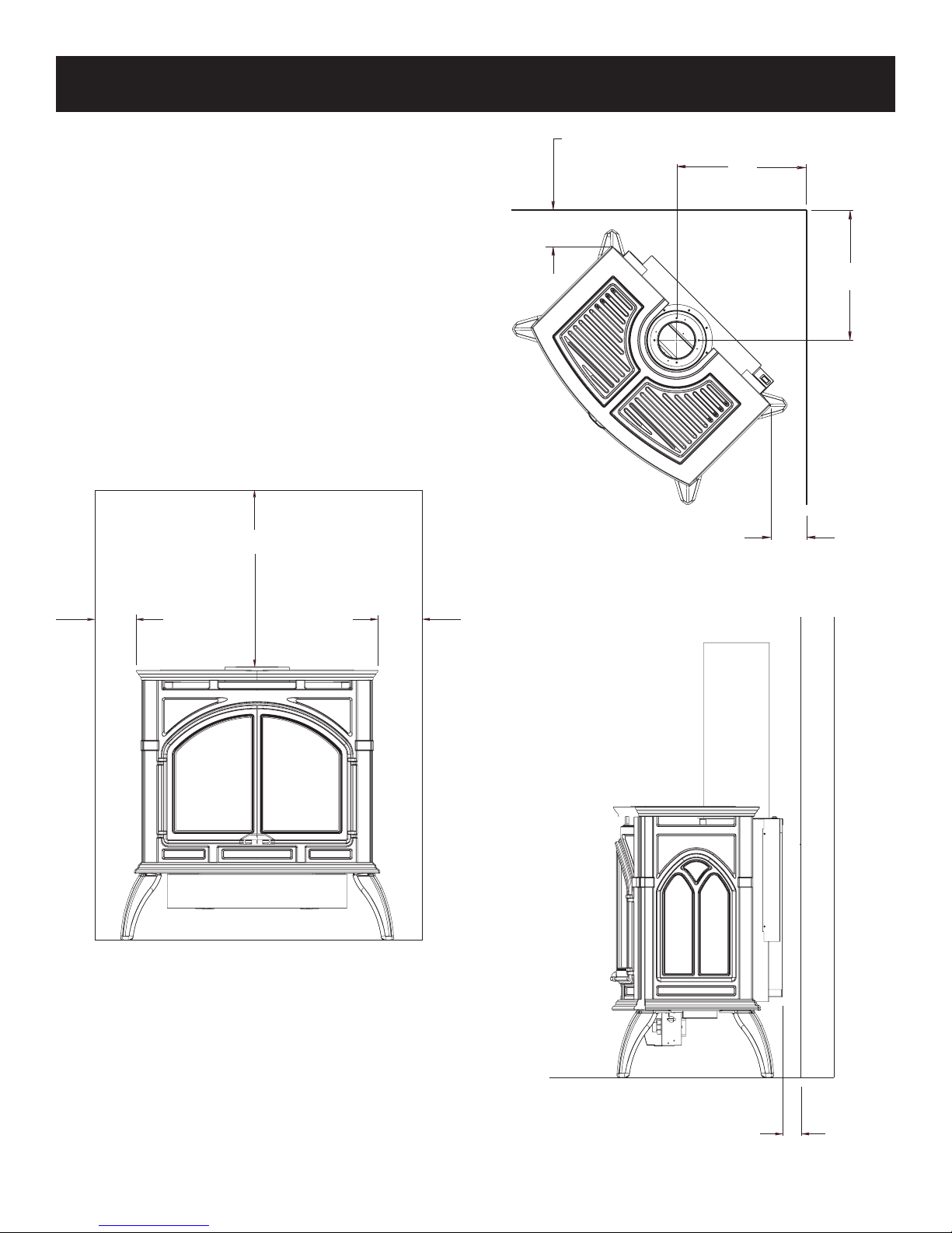
SPECIFICATIONS
Model
Natural Gas Propane (LP)
Input BTU/HR (KW/H) Maximum 32,000 (9.3) 30,000 (8.7)
BTU/HR (KW/H) Minimum 22,400 (6.5) 22,000 (6.4)
Height 27 3/4" (705 mm) 27 3/4" (705 mm)
Width
Depth 17 3/8" (442 mm) 17 3/8" (442 mm)
Gas Inlet (Pipe) 1/2" (13 mm) 1/2" (13 mm)
Floor to Center of 90° elbow with a 24" length of pipe
(See Figure 5)
Venting Accessories (Special Vent Kits - Simpson Duravent Can be purchased from Empire Comfort Systems Inc.)
DVKHP Direct-Vent Kit for Horizontal Run (46DVA-24B, 46DVA-09B,
46DVA-08AB, 46DVA-DC, 46DVA-WT, 46DVA-HC,
46DVA-E90B)
DVKVP Direct-Vent Kit for Vertical Run ((2) 46DVA-48B, 46DVA-DC,
46DVA-F6, 46DVA-SC, 46DVA-FS, 46DVA-VCH)
Accessories
TMV Millivolt Wall Thermostat - Reed Switch
FRBC Battery Operated Remote Control
FRBTC Battery Operated Remote Control with Thermostat
FREC Electric Remote Control
FWS Wall Switch
FRBTP 7-Day Programmable Remote
TRW Remote Wall Thermostat
CIB-3 Automatic Blower
Stone Inlay Replaces Standard Grill Top
CSI-8V Stone Inlay Venetian Gold
CSI-9A Stone Inlay Adobe Frost
CSI-10M Stone Inlay Patina Mocha
CSI-11G
CSI-12A Stone Inlay American Beauty
Cast Iron Stove Side Shelf Kit (Includes Left & Right)
CSK-B Side Shelf Kit Porcelain Black
CSK-F Side Shelf Kit Matte Black
CSK-M Side Shelf Kit Porcelain Mahogany
CSK-S Side Shelf Kit Porcelain Sand
CSK-W Side Shelf Kit Matte Pewter
Stone Inlay Temple Gray
28 1/16" (713 mm) 28 1/16" (713 mm)
56 1/4" (1428 mm) 56 1/4" (1428 mm)
DVP30CA30(B,F,S,M,W)
24032-2-1008 Page 7
GAS SUPPLY
1/2 NPT
NIPPL
E
1/2 NPT
NIPPL
E
Consult the current National Fuel Gas Code, ANSI Z223.1 CAN/
CGA-B149 (.1 or .2) installation code.
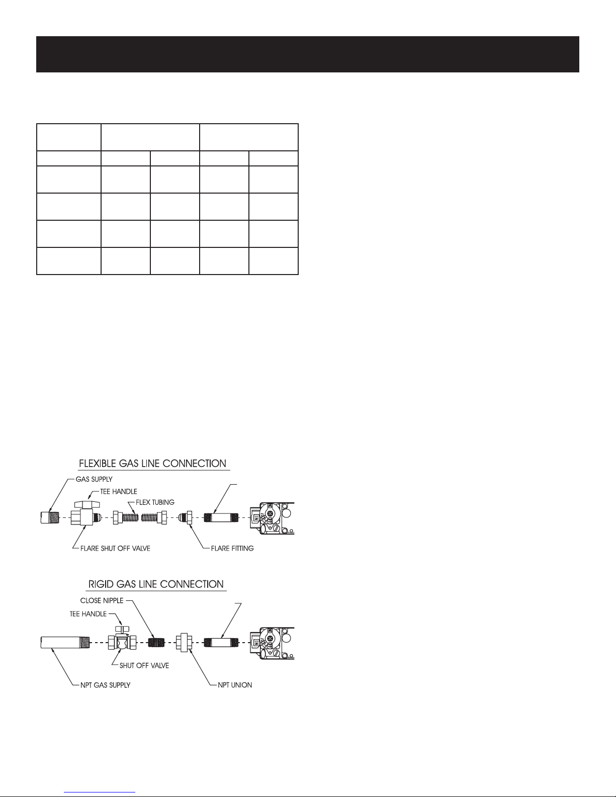
Recommended Gas Pipe Diameter
Pipe Length Schedule 40 Pipe
Inside Diameter
Tubing, Type L
Outside Diameter
Nat. L.P. Nat. L.P.
0-10 feet
0-3 meters
10-40 feet
4-12 meters
40-100 feet
13-30 meters
100-150 feet
31-46 meters
1/2”
12.7 mm
1/2”
12.7 mm
1/2”
12.7 mm
3/4”
19 mm
3/8”
9.5 mm
1/2”
12.7 mm
1/2”
12.7 mm
1/2”
12.7 mm
1/2”
12.7 mm
5/8”
15.9 mm
3/4”
19 mm
7/8”
22.2 mm
3/8”
9.5 mm
1/2”
12.7 mm
1/2”
12.7 mm
3/4”
19 mm
Note: Never use plastic pipe. Check to confirm whether your local
codes allow copper tubing or galvanized.
Note: Since some municipalities have additional local codes, it is
always best to consult your local authority and installation code.
The use of the following gas connectors is recommended:
— ANS Z21.24 Appliance Connectors of Corrugated Metal Tubing
and Fittings
— ANS Z21.45 Assembled Flexible Appliance Connectors of
Other Than All-Metal Construction
The above connectors may be used if acceptable by the authority
having jurisdiction. The state of Massachusetts requires that a flexible
appliance connector cannot exceed three feet in length.
Figure 1
Installing a New Main Gas Cock
Each appliance should have its own manual gas cock.
A manual main gas cock should be located in the vicinity of the
unit. Where none exists, or where its size or location is not ad
equate, contact your local authorized installer for installation or
relocation.
Compounds used on threaded joints of gas piping shall be resistant
to the action of liquefied petroleum gases. The gas lines must be
checked for leaks by the installer. This should be done with a soap
solution watching for bubbles on all exposed connections, and if
unexposed, a pressure test should be made.
Never use an exposed flame to check for leaks. Appliance must
be disconnected from piping at inlet of control valve and pipe
capped or plugged for pressure test. Never pressure test with
appliance connected; control valve will sustain damage!
NOTE: The gas control is equipped with a captured screw type
pressure test point, therefore it is not necessary to provide a 1/8"
test point up stream of the control.
A gas valve and ground joint union should be installed in the gas
line upstream of the gas control to aid in servicing. It is required
by the National Fuel Gas Code that a drip line be installed near
the gas inlet. This should consist of a vertical length of pipe tee
connected into the gas line that is capped on the bottom in which
condensation and foreign particles may collect.
When using copper or flex connector use only approved fittings.
Always provide a union so that gas line can be easily disconnected
for burner servicing.
The appliance and it's individual shut off valve must be disconnected
from supply piping system during any pressure testing of that system
at test pressures in excess of 1/2 psig (3.5 kPa).
The appliance must be isolated from the gas supply piping system
by closing its individual manual shut off valve during any pressure
testing of the gas supply piping system at test pressures equal to or
less than 1/2 psig (3.5 kPa).
Attention! If one of the procedures results in pressures in excess
of 1/2 psig (14" w.c.) (3.5 kPa) on the fireplace gas valve, it will
result in a hazardous condition.
Checking Manifold Pressure
Both Propane and Natural gas valves have a built-in pressure
regulator in the gas valve. Natural gas models will have a manifold
pressure of approximately 3.5" w.c. (.871 kPa) for maximum input
or 1.7" w.c. (.423 kPa) for minimum input at the valve outlet
with the inlet pressure to the valve from a minimum of 5.0" w.c.
(1.245 kPa) for the purpose of input adjustment to a maximum of
10.5" w.c. (2.615 kPa). Propane gas models will have a manifold
pressure approximately 10.0" w.c. (2.49 kPa) for maximum input
or 5.9" w.c. (1.469 kPa) for minimum input at the valve outlet
with the inlet pressure to the valve from a minimum of 11.0" w.c.
(2.739 kPa) for the purpose of input adjustment to a maximum of
13.0" w.c. (3.237 kPa).
A 1/8" (3 mm) N.P.T. plugged tapping, accessible for test gauge
connection, is located on the outlet side of the gas control.
-
24032-2-1008Page 8
CLEARANCES
6” (153mm)
TO SIDE
WALL
6” (153mm) TO
COMBUSTIBLE
MATERIAL
36” (915mm) TO CEILING OR
HORIZONTAL PROJECTION
ABOVE APPLIANCE
NOTE: HEATER INSTALLED AT 45° ANGLE IN CORNER
4” (102mm) HEATER CORNERS TO SIDE WALL
10”
(254mm)
10
”
(254mm)
4”
(102mm)
1” (25.4mm)
TO COMBUSTIBLE MATERIAL
In selecting a location for installation, it is necessary to provide
adequate accessibility clearances for servicing and proper operation.
Locating and Venting the Direct Vent Fireplace
Clearances: When facing the front of the direct vent fireplace the
minimum clearances to combustible construction (material) are
the following:
Top of appliance (ceiling) 36" (914.4 mm)
Rear Wall 1" (25.4 mm)
Side Wall 6" (152.4 mm)
Heater Corners (45° angle) to Wall 4" (101.6 mm)
Floor 0" (0 mm)
Installation on Rugs and Tile
This appliance must be installed on a flat, solid, continuous surface
(e.g. wood, metal, concrete). This may be the floor, or it may be
raised up on a platform to enhance its visual impact. The appliance may be installed on carpeting, vinyl, wood flooring or other
combustible material.
Figure 2
Figure 3
24032-2-1008 Page 9
Figure 4
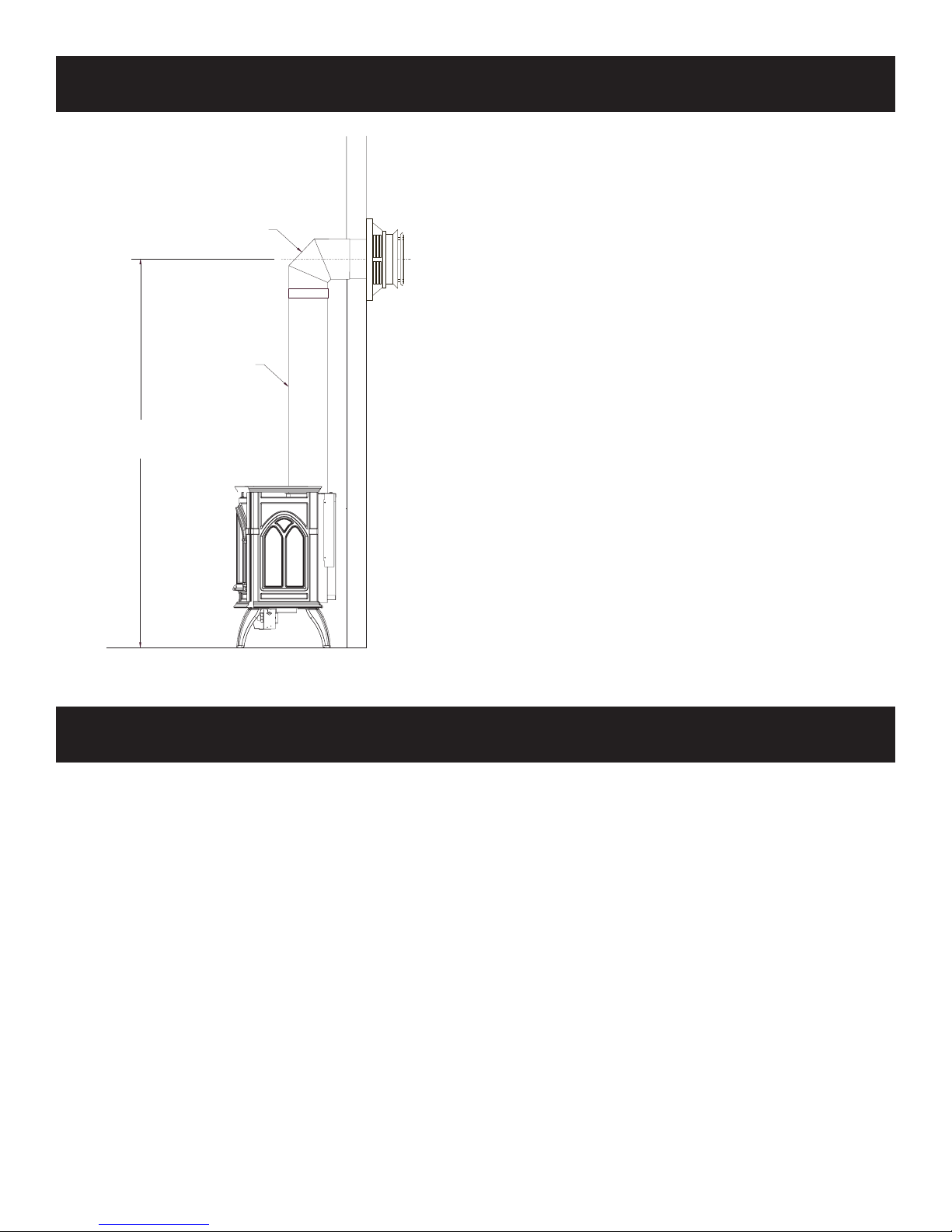
56 1/4”
(1.43 m)
90° ELBOW
24” PIPE SECTION
(610 mm)
CLEARANCES (cont.)
Special Vent Systems
The following vent systems are acceptable for use with the
DVP30CA fireplace:
Simpson Duravent® GS 4" - 6 5/8"
American Metal® 4" - 6 5/8"
*Selkirk Direct-Temp® 4" - 6 5/8"
* Can not be used in side wall horizontal vent installations in
the State of Massachusetts.
Figure 5
VENTING FIREPLACE
Venting Graph (Dimensions in Feet) (Figure 6)
1. Determine the height of the center of the termination. Using this
dimension on the Venting Graph, locate the point it intersects
with the slanted graph line, or the right edge of the graph.
2. From the point of this intersection, draw a vertical line to the
bottom of the graph.
3. Adjust the indicated maximum dimension for additional elbows
if necessary.
4. Position the unit so that maximum horizontal run is not
exceeded.
Venting Requirements (Figure 6)
Minimum vertical rise from appliance outlet before any elbows =
24 inches (610 mm).
Maximum vertical rise from appliance outlet = 25 feet (7.62 m),
the restrictor plate must be used above 10 feet.
Maximum horizontal run from appliance outlet = 12 feet
(3.66 m).
Maximum vertical rise and horizontal run is a combined total of
25 feet (7.62 m).
Maximum elbows = (2) 90°, for the second elbow subtract 5 feet
from a horizontal run.
To Use the Vent Graph
EXAMPLE A:
If the vertical rise from the appliance outlet is 21 feet, the horizontal
run to the outer wall flange of the vent termination must not exceed
4 feet with (1) 90° elbow.
EXAMPLE B:
If the vertical rise from the appliance outlet is 14 feet, the horizontal
run to the outer wall flange of the vent termination must not exceed
11 feet with (1) 90° elbow.
SPECIAL NOTE:
For each 45 degree elbow installed in the
horizontal run, the length of the horizontal run MUST be reduced by
18 inches (457.2 mm). This does not apply if the 45 degree elbows
are installed on the vertical rise of the vent system.
Example: According to the chart the maximum horizontal run is
12 feet and if two 45 degree elbows are required in the horizontal
run it must be reduced to 9 feet.
The maximum number of 45 degree elbows permitted per side
wall installation is two. These elbows can be installed in either the
vertical rise or horizontal run.
24032-2-1008Page 10
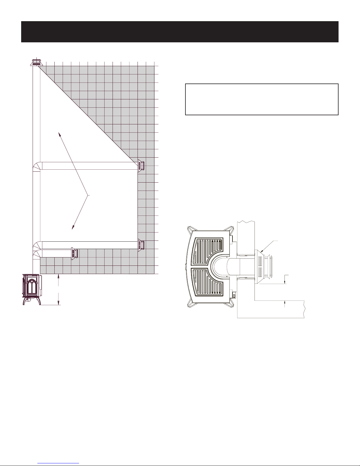
VENTING FIREPLACE (cont.)
VENT CAP
9” (229MM) TO SIDE
WALL
0
1 2
3
4 5 6
7
8
9
10
11
12
13
14
0
1
2
3
4
5
6
7
8
9
10
11
12
13
14
15
16
17
18
19
20
21
22
23
24
25
VENTING MUST
TERMINA
TE IN
THIS AREA
HORIZONT
AL RUN IN FEET
VERTICAL
RISE ABOVE
FIREPLACE
IN
FEET
28”
Sidewall Venting
The maximum vertical and horizontal distances are 25 feet and 12
feet, respectively. Vertical dimensions are based on top of fireplace
to centerline of pipe. Horizontal dimensions are based on centerline
of pipe to termination.
CAUTION: Total vertical run MUST BE completed before
starting horizontal run. Horizontal chimney run must slope
upward (away from fireplace) 1/4" per foot and vent
termination must be level.
Under no circumstances should combustible materials (including
siding) be closer than 2" from the top of the 6 5/8" pipe or closer
than 1" on the side and bottom.
Cutting the Hole (Figure 7)
After the appliance has been positioned in its permanent location,
the hole through the exterior wall of the house can be cut. This
hole needs to be 10" high x 10" wide square with its center line
determined by the amount of vertical arise and horizontal run of the
termination. When locating the hole it must be noted that the bottom
of the cap must be 12" above the ground level, and top of the cap
must be no less than 18" below a combustible projection, and no
Figure 6
closer than 9" to any wall running parallel to vent termination.
Figure 7
24032-2-1008 Page 11
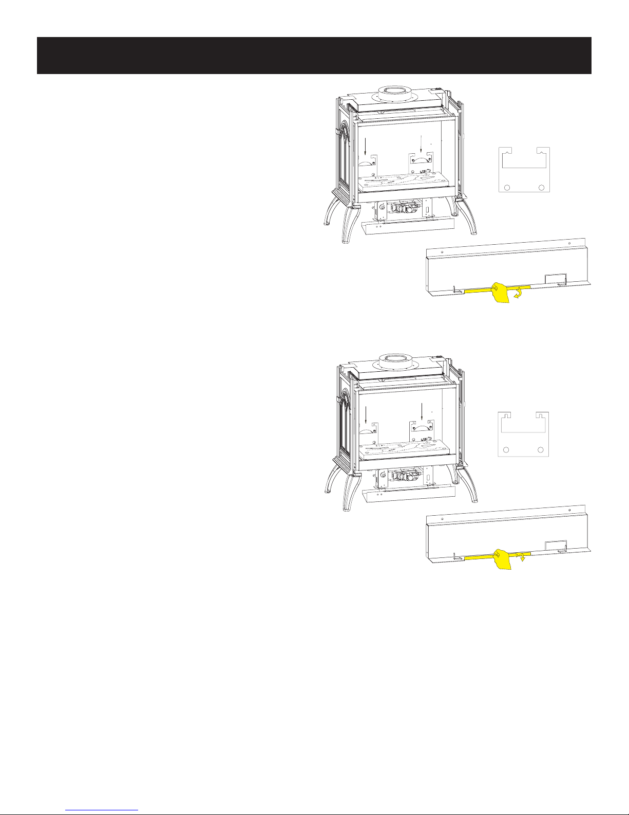
RESTRICTOR PLATE INSTALLATION
NAT
LPG
BEND 180 FOR NAT
O
BEND 90 FOR LPG
O
The restrictor plate is to be used only in a completely vertical vent
installation. The restrictor plate can be used when the vertical vent
rise is between 10 feet and 25 feet.
In a vertical vent rise the rear (yellow) flames on the main burner
can be reduced due to the drawing action from the flue exhaust pipe
and the air inlet pipe. A decrease in the height or the appearance of
the yellow flame may occur when the vertical vent rise is between
10 feet and 25 feet. To enhance the yellow flame on the main
burner, the restrictor plates need to be installed on both air inlet
holes behind the log shelf.
Please use the following steps to install the restrictor plate.
1. Remove cast iron top and carefully set aside.
2. Remove cast iron front and carefully set aside.
3. Carefully remove glass door.
4. Remove the log shelf by removing the (2) screws securing the
log shelf to the wall.
5. Loosen the upper (2) screws of both air inlet holes.
6. Slide restrictor plates down over loosened screws. Tighten (4)
screws securely.
7. Modify log shelf by bending tab on front edge flat for LP or
down for Natural gas.
8. Replace log shelf carefully by replacing the (2) screws.
9. Carefully replace glass door.
10. Replace cast iron front.
11. Replace cast iron top.
12. Installation of restrictor plate is completed.
Attention: Restrictor plates for Natural gas have diamond shaped
notches for mounting on screws. LP gas plates have square shaped
notches for mounting on screws. Be sure to use the proper restrictor
plate for the gas type.
Figure 8
Attention: See Page 30 to order restrictor plate.
Figure 9
24032-2-1008Page 12
 Loading...