

Empire Comfort Systems DVCT35CBN95N-1, DVCT30CBN95N-1, DVCT30CBN95P-1, DVCT35CBN95P-1 Installation Instructions And Owner's Manual
HOT GLASS
DO NOT TOUCH
NEVER
WILL
CAUSE BURNS.
GLASS
UNTIL COOLED.
ALLOW CHILDREN
TO TOUCH GLASS.
A barrier designed to reduce the risk of burns from the
hot viewing glass is provided with this appliance and shall
be installed for the protection of children and other at-risk
individuals.
DANGER
INSTALLATION INSTRUCTIONS
38102
INSTALLER:
Leave this manual with the appliance.
CONSUMER:
Retain this manual for future reference.
WARNING
FIRE OR EXPLOSION HAZARD
Failure to follow safety warnings exactly
could result in serious injury, death or
property damage.
— Do not store or use gasoline or other
ammable vapors and liquids in the
vicinity of this or any other appliance.
— WHAT TO DO IF YOU SMELL GAS
• Do not try to light any appliance.
• Do not touch any electrical switch; do
not use any phone in your building.
• Leave the building immediately.
• Immediately call your gas supplier
from a neighbor’s phone. Follow the
gas supplier’s instructions.
• If you cannot reach your gas supplier,
call the re department.
— Installation and service must be
performed by a qualied installer,
service agency or the gas supplier.
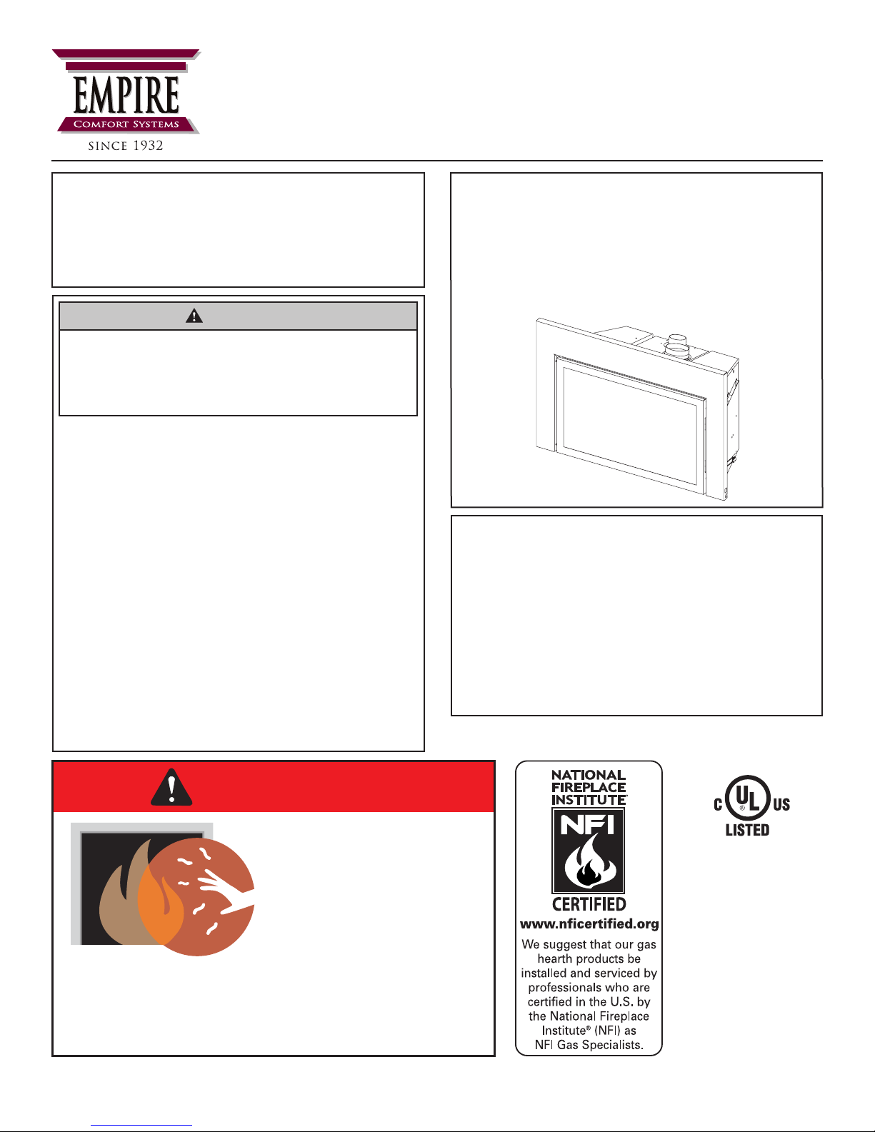
DIRECT VENT
GAS FIREPLACE HEATER
FIREPLACE
INSERT MODELS
DVCT(30,35)CBN95(N,P)-1
This appliance may be installed into a listed
wood-burning replace in an aftermarket,
permanently located, manufactured home
(USA only) or mobile home, where not
prohibited by state or local codes.
This appliance is only for use with the type
of gas indicated on the rating plate. This
appliance is not convertible for use with
other gases, unless a certied kit is used.
GAS-FIRED
UL FILE NO. MH30033
This replace is design
certied in accordance
with American National
Standard/CSA Standard ANSI Z21.88/CSA
2.33 and by Underwriters Laboratories as a
Direct-Vent Gas Fireplace Heater and shall
be installed according
to these instructions.
Page 1

TABLE OF CONTENTS
SECTION PAGE
Attention Installer ........................................................................................................................................ 3
Before You Start ......................................................................................................................................... 4
Carton Contents & Hardware Pack ............................................................................................................ 5
Specications ............................................................................................................................................. 6
Accessories ................................................................................................................................................ 7
Venting Accessories ................................................................................................................................... 7
Introduction ..............................................................................................................................................8-9
Fireplace Insert Dimensions ..................................................................................................................... 10
Minimum Fireplace Opening Dimensions ..................................................................................................11
Mantel and Trim Clearances ......................................................................................................................11
Gas Supply .......................................................................................................................................... 12-13
Electrical Considerations .......................................................................................................................... 13
Fireplace Preparation ............................................................................................................................... 14
Venting ...................................................................................................................................................... 15
Vertical Termination .................................................................................................................................. 16
Installation ...........................................................................................................................................17-21
IPI System Electronic System Wiring Diagram ......................................................................................... 22
Intermittent Pilot Lighting Instructions ....................................................................................................... 23
Safety Information for Users of Propane .................................................................................................. 24
Intermittent Control System Troubleshooting ...................................................................................... 25-27
Insert Parts List .................................................................................................................................... 28-29
Insert Parts View ...................................................................................................................................... 29
Master Parts Distributor List ..................................................................................................................... 30
How To Order Repair Parts ...................................................................................................................... 30
Important Safety Information .................................................................................................................... 31
Warranty ................................................................................................................................................... 32
38102-1-0318Page 2

ATTENTION INSTALLER:
Fireplace Installation Checklist
Use this checklist in conjunction with the instructions in this manual.
Customer: _____________________________________
Lot/Address: ___________________________________
_______________________________________________
Model: ________________________________________
Serial #: ________________________________________
Date Installed: __________________________________
Fireplace Location: ______________________________
Installer: _______________________________________
Dealer Phone #: _________________________________
_______________________________________________
FIREPLACE INSTALLATION COMMENTS
Veried clearances to combustibles (pg. 11)........................................................................ o ____________________
Fireplace is leveled and secured .......................................................................................... o ____________________
VENTING/CHIMNEY/PowerFlow™ HEAT DISTRIBUTION
Venting conguration complies to vent diagrams (pgs. 15 - 18) .......................................... o ____________________
Venting installed, locked, secured in place with correct clearance ....................................... o ____________________
Firestops installed................................................................................................................. o ____________________
Exterior wall/roof ashing installed and sealed..................................................................... o ____________________
Terminations installed and sealed (pg. 16)........................................................................... o ____________________
Light unit and test venting before enclosing the replace .................................................... o ____________________
ELECTRICAL (pgs. 13 and 22)
Unswitched power (110-120 VAC) provided to the replace ................................................ o ____________________
GAS (pgs. 12 - 13)
Proper appliance for fuel type............................................................................................... o ____________________
Was a conversion performed? .............................................................................................. oYes oNo
Leak check performed and inlet pressure veried ................................................................ o ____________________
FINISHING
Veried all clearances meet installation manual requirements ............................................. o ____________________
Mantels and wall projections meet requirements (pg. 11) .................................................... o ____________________
Granite or Clean Face nishing complies with clearance requirements screen ................... o ____________________
Barrier for glass front properly installed ................................................................................ o ____________________
FIREPLACE SETUP
All packaging and protective materials removed (inside & outside of replace) .................. o ____________________
Media installed correctly ....................................................................................................... o ____________________
Firebox glass door cleaned, installed, and secured ............................................................. o ____________________
Accessories installed properly .............................................................................................. o ____________________
Started Fireplace and checked for gas leaks ....................................................................... o ____________________
Manual envelope and all contents removed from the replace and given homeowner ........ o ____________________
Empire recommends the following:
• Keep this checklist visible on the replace until the installation is complete.
• Photograph the installation and copy this completed checklist for your le.
Comments: Further description of any issues, who is responsible (Installer/Builder/Other, etc) and corrective action needed:
___________________________________________________________________________________________________________
Comments communicated to responsible party _____________________by _____________________ on ______________________
38102-1-0318 Page 3
BEFORE YOU START
WARNING
Read and follow these safety precautions prior to operating
this appliance. Failure to follow these precautions may
result in death, injury, or property damage.
Sample Warnings and Denitions:
DANGER
Indicates a hazardous situation which, if not avoided, will
result in death or serious injury.
WARNING
Indicates a hazardous situation which, if not avoided, could
result in death or serious injury.
CAUTION
Indicates a hazardous situation which, if not avoided, could
result in minor or moderate injury.
NOTICE: Addresses practices not related to personal injury.
Read all instructions before starting installation and follow them
carefully to insure safety. Failure to follow the instructions will
void the warranty and may cause a re hazard.
NOTICE: If the replace insert is installed into a modied wood-
burning, factory-built replace, the replace cannot be returned
to a wood-burning replace. See page 14 for additional details
regarding the allowed modications to a factory-built replace.
The warranty will be voided by, and the warranter disclaims any
responsibility for the following actions:
• Installation of any damaged replace insert or vent system
component.
• Modication of the replace insert or direct vent system.
• Installation other than as instructed by Empire Comfort
Systems Inc.
• Improper positioning of logs, glass door, barrier screen, or
decorative accessories.
• Installation and/or use of any component not manufactured
or approved by the manufacturer.
All correspondence should refer to complete Model Number,
Serial Number and type of gas. Fill out the Homeowner
Reference Section in Homeowner's manual on page 2.
Unpacking the replace insert
1. Cut the binding straps.
2. Remove the top carton.
3. Carefully remove the carton contents.
4. Use the Carton Contents and Hardware Pack lists on page 5
to verify all components are present.
5. Verify that the replace insert and components have not
been damaged during shipping.
6. Set the replace insert near installation location.
Preparation
This replace insert and its components are safe when installed
in accordance with this Installation Manual. Report any parts
damaged in shipment to your dealer. Do not install the replace
insert with damaged, incomplete or substitute parts.
Installation Considerations
• The rebox must be in good working order and sized
according to pages 11 and 14.
• Gas supply piping – right or left side entrance
• Electrical supply and connections – for blower
• 120V, 60Hz, 1 Amp
• Right side entrance
• Surround Requirements - See Fireplace Insert Dimensions,
page 10 and Accessories, page 7.
• Surround Bottom Cover - For elevated insert installations.
See dealer for custom surrounds.
• Leveling the Insert - Four leveling bolts are included in the
Hardware Pack. See page 17 for installation and use.
Planning The Installation
1. Read the safety information on pages 24 and 31.
2. Place the sticker located in the instruction envelope onto
the “Homeowner Reference Information” in Homeowner's
manual on page 2.
3. Show the homeowner where the rating plate and lighting
instruction plate are located.
4. Install the venting. See pages 15 - 18.
5. Install and connect the gas lines. See pages 12 and 13.
6. Install the wiring. See page 22.
7. Install the replace insert. See pages 17 - 21.
8. Remove the barrier and door assemblies.
9. Install the liners, log set, and rock wool. See their manuals.
10. Sync the remote. See page 19.
11. Install the surround. See page 20.
12. Reinstall the door assembly. See page 21.
13. Light the replace insert. See page 23.
14.
Adjust the damper, air shutters, and rock wool for perfect burn.
15.
Troubleshoot any issues. See pages 24 - 26.
16. Reinstall the barrier assembly.
17. Install the decorative front. See their manuals.
18. Show the homeowner how to operate the replace insert.
19. Show the homeowner how do the basic maintenance.
20. Instruct the homeowner to never attempt to adjust the air
shutters or damper.
TrueFlame Technology
This replace is equipped with TrueFlame Technology for
maximum ames and ember glow with minimum emissions. The
system includes independently controlled front and rear burners
set into a large ember bed plus a ceramic catalyst and externally
adjustable bafe mounted at the top. Once adjusted by the
dealer/technician at installation, the TrueFlame system requires
no further adjustment.
38102-1-0318Page 4
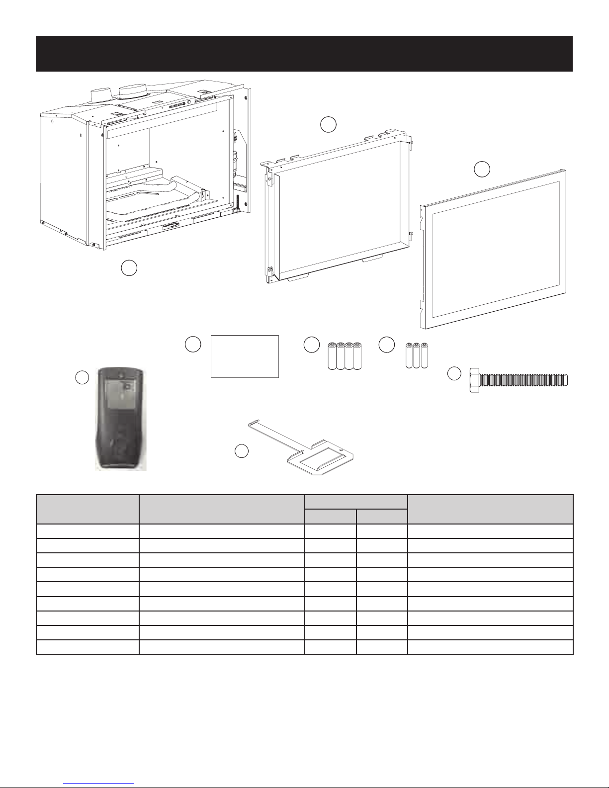
CARTON CONTENTS & HARDWARE PACK
9
2
1
3
4
Rockwool
7
INDEX NUMBER DESCRIPTION
1 Fireplace Insert 1 1 In Carton
2 Glass Door Assembly 1 1 Front of Insert
3 Barrier Screen Assembly 1 1 Front of Insert
4 Rockwool Embers 1 1 In Envelope
5 AA Batteries 4 4 In Envelope
6 AAA Batteries 3 3 In Envelope
7 Remote 1 1 In Bag Inside Insert
8 5/16-18 x 2-1/2” Hex Head Bolt 4 4 In Envelope
9 Latch 1 1 Left Side Of Insert
5
QUANTITY SUPPLIED
DVCT30 DVCT35
6
8
LOCATION
38102-1-0318 Page 5
SPECIFICATIONS
DVCT30CBN95(N,P)-1 DVCT35CBN95(N,P)-1
Propane Natural Propane Natural
Input BTU/Hr Maximum (Both Burners High) 28,500 30,000 35,000 39,000
Input BTU/Hr Minimum (Both Burners Low) 22,000 19,500 28,500 25,500
Input BTU/Hr Minimum (Only Front Burner Low) 10,000 8,500 11,000 10,000
KWH (Maximum) 8.34 8.78 10.2 11.4
KWH (Minimum) (Front Burner Only) 2.93 2.49 3.2 2.9
Orice (Rear) 1.20mm #47 1.40mm 2.40mm
Orice (Front) #59 #52 #57 #50
Air Shutter Opening (Rear) Fully Open Fully Closed Fully Open Fully Closed
Air Shutter Opening (Front) Fully Open Fully Closed Fully Open Fully Closed
Gas Inlet Shutoff Valve (Pipe) 3/8 MIF 3/8 MIF 3/8 MIF 3/8 MIF
NOTICE: Air shutter settings are factory minimum settings. Some venting congurations may require minor air shutter adjustments for
optimum performance.
GAS SUPPLY PRESSURES
Gas Type Maximum Minimum Manifold
Natural 14 4.5 3.5
Propane 14 10.8 10
38102-1-0318Page 6
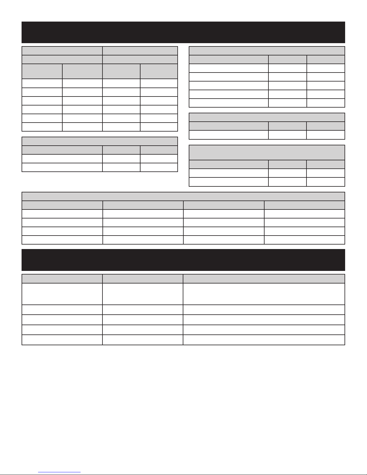
ACCESSORIES
DVCT30 DVCT35
SURROUNDS (REQUIRED) SURROUNDS (REQUIRED)
Description
(Black)
36 x 24 x 1 DS30631BL 40 x 29 x 1 DS35631BL
40 x 27 x 1 DS30961BL 44 x 31 x 1 DS35961BL
42 x 29 x 1 DS301071BL 48 x 33 x 1 DS351071BL
44 x 31 x 1 DS301271BL 52 x 36 x 1 DS351271BL
36 x 24 Flush DS3063BL 40 x 29 Flush DS3563BL
42 x 29 Flush DS30107BL 48 x 33 Flush DS35107BL
Description DVCT30 DVCT35
Traditional Charred LS30TINF LS35TINF
Driftwood LS30DINF LS35DINF
Kit Number Conversion Type Used On Valve Type
38289 Natural to Propane DVCT30CBN95N IP
38290 Propane to Natural DVCT30CBN95P IP
38499 Natural to Propane DVCT35CBN95N IP
38500 Propane to Natural DVCT35CBN95P IP
Model
Number
LOG SET (REQUIRED)
Description
(Black)
Model
Number
GAS CONVERSION KITS
DVCT30 LINER (REQUIRED)
Description DVCT30 DVCT35
Porcelain Black DVP30CPKR DVP35CPKR
Rustic Brick DVP30CPMB DVP35CPMB
Cottage Brick DVP30CPTB DVP35CPTB
Traditional Stone DVP30CPTS DVP35CPTS
Old World Stone DVP30CPWS DVP35CPWS
DVCT30 DECORATIVE FRONT (OPTIONAL)
Description DVCT30 DVCT35
Forged Iron Window Frame DFF30FPD DFF35FPD
DVCT30 DECORATIVE FRONT INSETS
(REQUIRES DECORATIVE FRONT DFF(30,35)FPD)
Description DVCT30 DVCT35
Arch Forged Iron Inset DFF30RPD DFF35RPD
Rectangle Forged Iron Inset DFF30CPD DFF35CPD
VENTING ACCESSORIES
VENTING KITS DESCRIPTION CONTENTS
SD46DVACL34
SD3DFA35 Flexliner, 3-inch x 35 feet 35 feet of 3-inch Diameter Pipe With 2 Clamps
SD4DFA35 Flexliner, 4-inch x 35 feet 35 feet of 4-inch Diameter Pipe With 2 Clamps
DVIC3 3-inch Connector Kit 3-inch Connector With 2 Clamps
DVIC4 4-inch Connector Kit 4-inch Connector With 2 Clamps
NOTICE: When installing vent caps, special locally made ashings may be required to properly seal the vent system to the existing
chimney termination.
Vertical Vent Kit
(3-inch x 4-inch)
High-wind round cap, ashing, 35 feet of 3-inch diameter pipe, 35
feet of 4-inch diameter pipe, and clamps. Recommended when
installing to an existing round replace chimney pipe.
38102-1-0318 Page 7
INTRODUCTION
Instructions to Installer
1. Leave this manual with the homeowner.
2. Have the homeowner ll out and mail the Product
Registration Card supplied with the replace insert or online
at www.empirecomfort.com.
3.
Show the homeowner how to start and operate the
replace insert.
4. Attach the warning label plate supplied with the insert to
the inside of the rebox of the replace into which the gas
replace insert is installed.
5.
Run replace insert for a minimum 30 to 35 minutes to burn
off oils from manufacturing. Failure to perform this initial
burn-off can cause pilot problems. After burn-off, clean ame
sensor on IP pilot assembly. See page 39 for sensor location.
Important
Refer to complete Model Number, Serial Number and gas type
in all correspondence.
Qualied Installing Agency
Installation and replacement of gas piping, gas utilization
equipment or accessories and repair and servicing of equipment
shall be performed by a qualied agency. The term “qualied
agency” means any individual, rm, corporation or company
which either in person or through a representative is engaged
in and is responsible for (a) the installation or replacement of
gas piping or (b) the connection, installation, repair or servicing
of equipment, who is experienced in such work, familiar with all
precautions required and has complied with all the requirements
of the authority having jurisdiction.
Commonwealth of Massachusetts: The installation must be
made by a licensed plumber or gas tter in the Commonwealth
of Massachusetts.
Installation and repair should be done by a qualied service
person. The appliance should be inspected before use and at least
annually by a qualied service person. More frequent cleaning
may be required due to excessive lint from carpeting, bedding
material, etc. It is imperative that control compartments, burners
and circulating air passageways of the appliance be kept clean.
High Altitude
When installing this unit at an elevation above 2000 feet (in
the United States) it may be necessary to decrease the input
rating by changing the existing burner orice to a smaller size.
Generally, input should be reduced 4 percent for each 1000 feet
above sea level. However, if the heating value of the gas has
been reduced, this general rule may not apply. Conrm orice
size with Empire Comfort Systems.
Canadian High Altitude
Altitude: 0-4500 feet (0-1370 m)
When installing this unit at an elevation above 4500 feet (in
Canada), check with local authorities.
Consult your local gas utility for assistance in determining the
proper orice for location.
Well Head Gas Installations
Some Natural Gas utilities use “well head” gas. This may affect
the Btu output of the unit and promote sooting. Units shall not be
converted to use well head gas.
Building Codes
Consult your local building code agency, prior to installation,
to ensure compliance with local codes-including permits and
inspections.
• The installation must conform with local codes or, in the
absence of local codes, with the National Fuel Gas Code
ANSI Z223.1/NFPA 54* Natural Gas and Propane Installation
Code, or CSA B149.1 in Canada. *Available from the
American National Standards Institute, Inc. 11 West 42nd
St., New York, N.Y. 10036.
• The replace insert, when installed, must be electrically
grounded in accordance with local codes or, in absence of
local codes, with the National Electric Code ANSI/NFPA
70 or Canadian Electric code, CSA C22.1, if an external
electrical source is utilized.
Preparation
This direct-vent gas replace insert and its components are
tested and safe when installed in accordance with this installation
manual. The replace insert must be installed into a wood-burning
replace. Report any parts damaged in shipment; specically
check glass condition. Do not install this unit with damaged,
incomplete, or substitute parts. Read all instructions before
starting installation and follow these instructions carefully during
installation to ensure maximum benet and safety. Failure to
follow them will void the warranty and may present a re hazard.
This direct-vent gas replace insert is designed to operate with
combustion air siphoned from and all exhaust gases expelled
to the outside of the building. The information contained in this
manual pertains to all models and gas control systems listed on
the front page unless otherwise noted.
These models may be installed in a bedroom or bed-sitting room
in the U.S.A. and Canada.
WARNING
Any change to this replace insert or its controls can be
dangerous. Improper installation or use of the replace
insert can cause serious injury or death from re, burns,
explosions, or carbon monoxide poisoning.
Before enclosing the vent pipe assembly, operate the
appliance to ensure it is venting properly.
Do not operate this appliance without the glass door installed.
• Due to high temperatures, the appliance must be located out
of trafc and away from furniture and draperies.
• Only surrounds supplied by the manufacturer shall be used
in the installation of this appliance.
• A barrier designed to reduce the risk of burns from the
hot viewing glass is provided with this appliance and shall
be installed for the protection of children and other at-risk
individuals.
• If the barrier or glass front is removed during servicing or
cleaning, it must be installed prior to operating the appliance.
• If the barrier becomes damaged, it must be replaced with the
manufacturer’s barrier for this appliance.
• Only doors certied with the appliance shall be used.
38102-1-0318Page 8

INTRODUCTION (CONT’D)
• This appliance comes standard with a 120 VAC cord
assembly to accommodate the blower accessory. A junction
box may be installed in a bottom back corner of the existing
solid fuel masonry or factory built replace to connect the
cord assembly, or the supplied power cord may be routed
out onto the hearth to a nearby outlet.
• A 120 VAC circuit for this product must be protected with
ground-fault circuit-interrupter protection, in compliance
with the applicable electrical codes, when it is installed in
locations such as in bathrooms or near sinks.
• Low voltage and 120 VAC cannot be shared within the same
wall box.
• Once the appliance is installed check that the control
compartment wiring is secured so as to not interfere with the
blower, door latches, valve controls, or the barrier assembly.
Warranty Requirements
Any alteration of the original design, installed other than as
shown in these instructions or use with a type of gas not shown
on the rating plate is the responsibility of the person and
company making the change.
The warranty will be voided by, and the warranter disclaims any
responsibility for the following actions:
• Installation of any damaged replace insert or vent system
component.
• Modication of the replace insert or direct vent system.
• Installation other than as instructed by Empire Comfort
Systems, Inc.
• Improper positioning of the logs or glass door assembly.
• Installation and/or use of any component part not
manufactured or approved by manufacturer.
38102-1-0318 Page 9
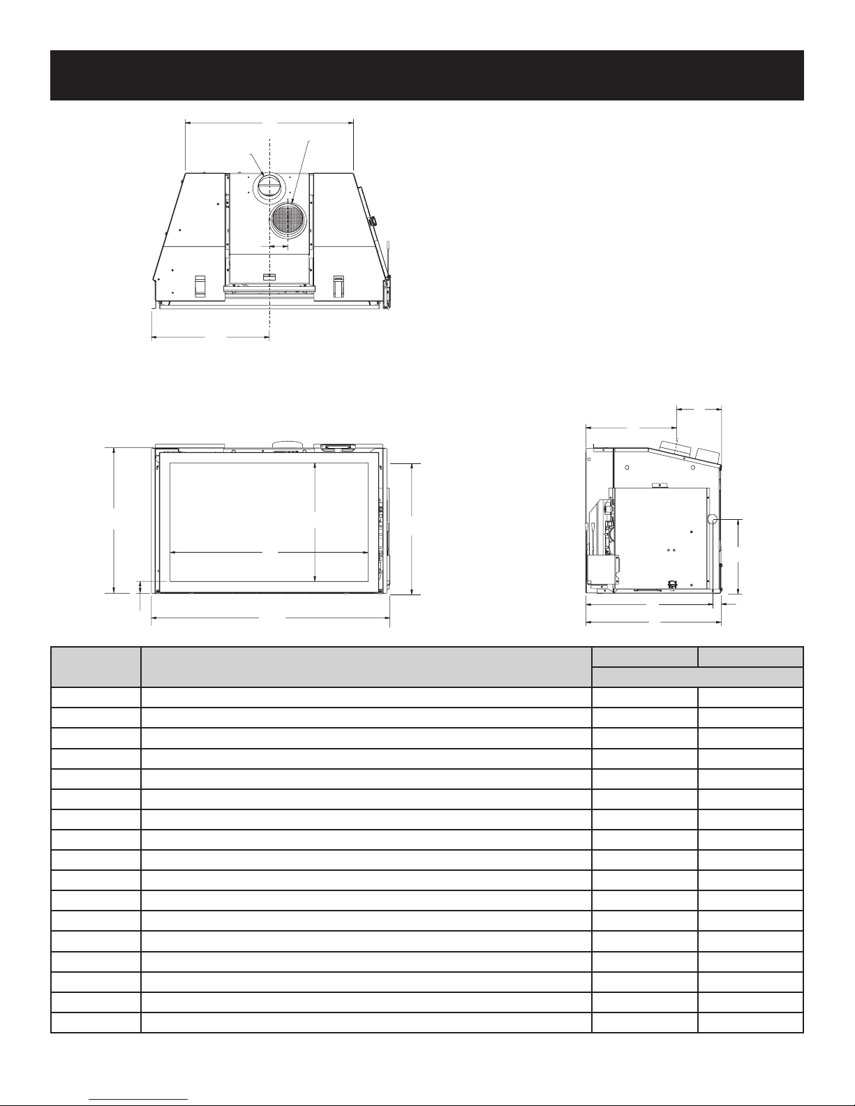
FIREPLACE INSERT DIMENSIONS
G
INTAKE
3" DIA
FLUE
4" DIA
2.375”
I
J
P
A
N
R
O
L
Q
INDEX
LETTER
A The maximum height of replace face 19 24
B The maximum width of replace face 30-11/16 34-3/4
C The maximum depth of replace 17-9/16 18-9/16
D The height of the replace opening (not shown) 15-3/4 20-3/4
E The width of the replace opening (not shown) 25-5/16 29-3/8
F The interior depth of the replace (not shown) 12-3/8 13-3/8
G The rear exterior width of the replace 21-11/16 25-1/8
I Width from the left side of the replace to the centerline of the intake 15-1/8 17-1/8
J Depth from back of replace to centerline of top ue 5-7/8 6-15/16
K Height from the bottom of the replace to the gas line opening 9-3/4 9-1/4
L Depth from the front of the replace to the gas line opening 16-7/16 16-13/16
M Depth from the rear of replace to gas line opening 1-1/8 1-13/16
N Viewing area height 14-7/8 19-7/8
O Viewing area width 25-1/4 29-1/4
P Depth from front of replace to centerline of ue 11-5/8 11-5/8
Q Distance from oor to bottom replace opening 1-3/4 1-3/4
R Distance from oor to top replace opening 17 22
B
DIMENSION DESCRIPTION
C
DVCT30 DVCT35
DIMENSIONS IN INCHES
K
M
38102-1-0318Page 10
 Loading...