

Empire Comfort Systems DVCP36PP3 SERIES, DVCP36SP7 SERIES, DVCP36SP3 SERIES, DVCP36PP7 SERIES Installation Instructions And Manual
INSTALLATION INSTRUCTIONS
AND OWNER’S MANUAL
INSTALLER: Leave this manual with the appliance.
CONSUMER: Retain this manual for future reference.
WARNING
FIRE OR EXPLOSION HAZARD
Failure to follow safety warnings exactly
could result in serious injury, death or
property damage.
— Do not store or use gasoline or other
ammable vapors and liquids in the
vicinity of this or any other appliance.
— WHAT TO DO IF YOU SMELL GAS
• Do not try to light any appliance.
• Do not touch any electrical switch; do
not use any phone in your building.
• Leave the building immediately.
• Immediately call your gas supplier
from a neighbor’s phone. Follow the
gas supplier’s instructions.
• If you cannot reach your gas supplier,
call the re department.
— Installation and service must be
performed by a qualied installer, service
agency or the gas supplier.
DIRECT VENT ZERO CLEARANCE
GAS FIREPLACE HEATER
MODEL SERIES:
GAS-FIRED
MILLIVOLT (MV)
DVCP36(PP,SP)30(N,P)-1
INTERMITTENT PILOT (IPI)
DVCP36(PP,SP)70(N,P)-1
UL FILE NO. MH30033
This appliance may be installed in an
aftermarket, permanently located,
manufactured home (USA only) or mobile
home, where not prohibited by local codes.
This appliance is only for use with the type
of gas indicated on the rating plate. This
appliance is not convertible for use with
other gases, unless a certied kit is used.
WARNING
If not installed, operated and maintained in
accordance with the manufacturer’s instructions,
this product could expose you to substances in
fuel or from fuel combustion which can cause
death or serious illness.
WARNING
HOT GLASS
CAUSE BURNS.
DO NOT TOUCH
UNTIL COOLED.
NEVER
A barrier designed to reduce the risk of burns from the
hot viewing glass is provided with this appliance and shall
be installed for the protection of children and other at-risk
individuals.
NOTICE: Barriers required and pre-installed on replace.
ALLOW CHILDREN
TO TOUCH GLASS.
WILL
GLASS
Page 1
BEFORE YOU START
Sample Warnings and Denitions:
DANGER
Indicates a hazardous situation which, if not avoided, will result
in death or serious injury.
WARNING
Indicates a hazardous situation which, if not avoided, could
result in death or serious injury.
CAUTION
Indicates a hazardous situation which, if not avoided, could
result in minor or moderate injury.
NOTICE: Addresses practices not related to personal injury.
1. Read the safety information on Pages 75 - 76.
2. If located in the Commonwealth of Massachusetts, please
note the special requirements on page 77.
3. Are you going to install a blower into the replace? See
pages 8 - 9.
4. Where are you going to install the replace? See page 17.
5. Frame the opening. See page 19.
6. Install the gas lines. See page 16.
7. Install the wiring. See pages 59 and 63.
8. Install the venting. See pages 25 - 32.
9. Install the replace. See pages 19 - 24.
10. Connect the venting system. See pages 33 - 34.
11. Install the logs. See page 36 - 54.
12. Light the replace and troubleshoot. See pages 60 - 61 and
64 - 67.
13. Show the homeowner how to operate the replace.
14. Show the homeowner how to do the basic maintenance.
Unpacking the replace
NOTICE: The barrier screens supplied with this replace may
be damaged if force is applied to their surfaces. Take care not to
push against barrier screens.
1. Cut binding straps and shrink wrap. Shrink wrap should be
cut vertically along a corner post to avoid damage to barrier
screens.
2. Remove and discard corner posts.
3. Remove and discard top plywood sheet.
4. Verify that the replace has not been damaged during
shipping.
5. Remove non-combustible board on vent-end of replace and
set aside (peninsula only).
6. Remove replace from pallet.
7. Remove non-combustible boards from pallet and set aside.
8. Set replace in a location near to its nal installation location.
NOTICE: It is not necessary to remove the barrier screens from
the glass frames in order to remove the glass frames (see page
69).
Installation Considerations - Fireplace Installation
Guidelines
When planning a replace installation, it’s necessary to
determine:
• If the desired location of the replace is compatible with the
required framing dimensions, clearances to combustibles, venting
requirements, etc.
• If optional accessories are desired.
• Routing of gas supply piping (vent-end entrance).
• Electrical connections - for IP control system or optional light
or blower kit (vent-end connection)
• Electrical supply requirements for IP control system or
optional light or blower kit. (120V, 60Hz, 1Amp) (Vent-end
connection)
The replace can be mounted on any of these surfaces:
1. A at hard combustible or non-combustible surface.
2. A raised platform of combustible or non-combustible material.
3. If allowed by local codes: A rectangular frame that contacts
all four edges on the bottom of the replace.
If the replace is installed directly on carpeting, tile or other
combustible material other than wood ooring, it should be
installed on a metal or wood panel extending the full width and
depth of the replace.
This replace is designed to be installed in a zero-clearance
enclosure. This means the combustible material can come in
contact with the top and side standoff spacers, and secured to
combustible framing using the framing brackets provided.
36092-2-0316Page 2
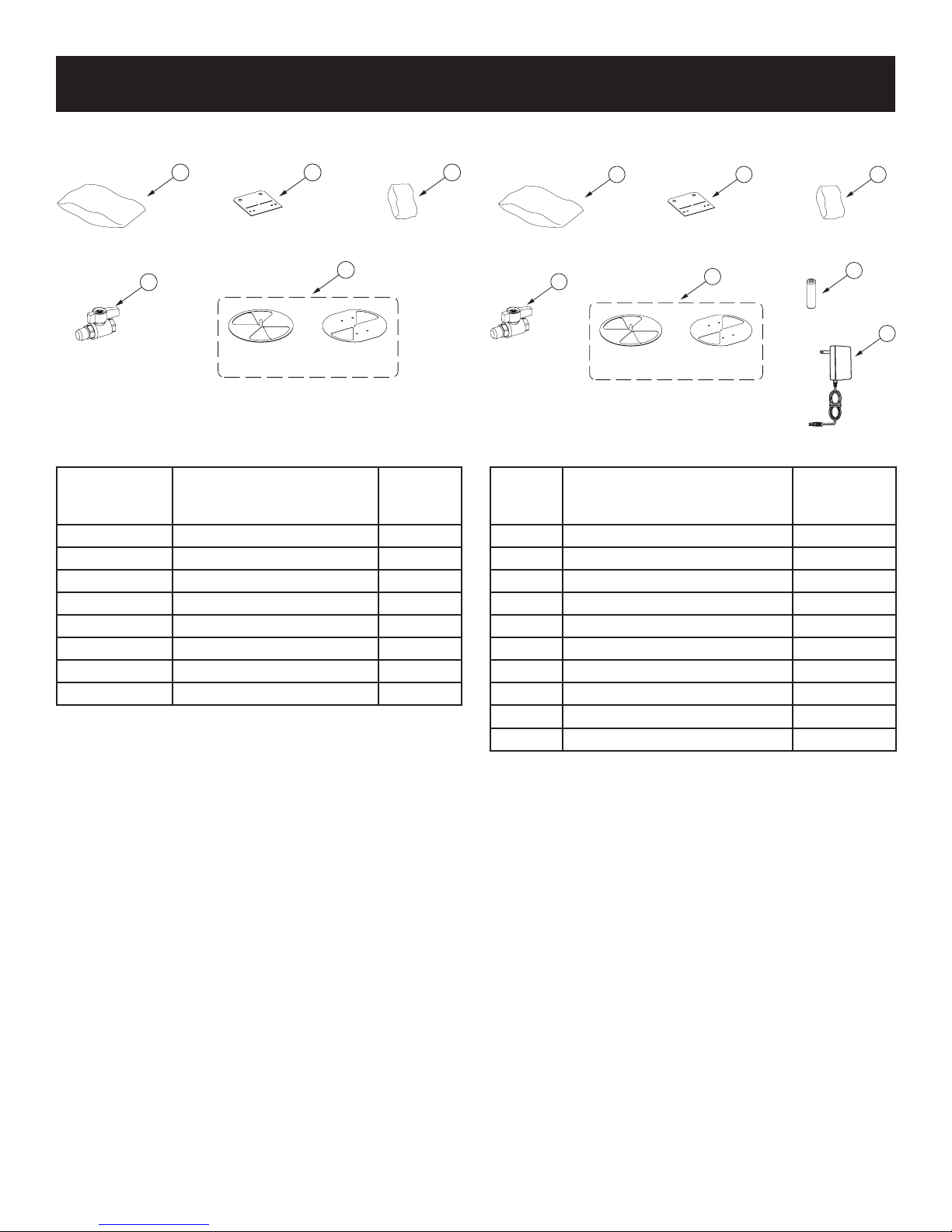
CARTON CONTENTS & HARDWARE PACK
CARTON CONTENTS - DVCP36(PP,SP)3 SERIES CARTON CONTENTS - DVCP36(PP,SP)7 SERIES
1 2 3
4
5
LP UnitNAT Unit
Items not shown to scale.
INDEX NO. DESCRIPTION
QUANTITY
SUPPLIED
1 Rock Wool 1
2* Nailing Flange 5
3 Hardware Pack 1
4 Shut-Off Valve 1
5 Flue Restrictor 1
NS Non-Combustible Board - Long 2
NS** Non-Combustible Board - Short 1
NS Installation Instructions 1
NS - Not Shown in reference graphic.
*Five required for Peninsula models. Four required for See-Thru
models.
**Peninsula models only.
See Parts Lists on pages 70 - 73 for ordering replacement parts.
Do not order batteries, bolts, screws, washers or nuts. They are
standard hardware items and can be purchased at any local
hardware store.
1 2 3
4
5
LP UnitNAT Unit
6
Items not shown to scale.
INDEX
NUMBER
DESCRIPTION
QUANTITY
SUPPLIED
1 Rock Wool 1
2* Nailing Flange 5
3 Hardware Pack 1
4 Shut-Off Valve 1
5 Flue Restrictor 1
6 Battery 4
7 AC Adapter 1
NS Non-Combustible Board - Long 2
NS** Non-Combustible Board - Short 1
NS Installation Instructions 1
NS - Not Shown in reference graphic.
*Five required for Peninsula models. Four required for See-Thru
models.
**Peninsula models only.
See Parts Lists on pages 70 - 73 for ordering replacement parts.
Do not order batteries, bolts, screws, washers or nuts. They are
standard hardware items and can be purchased at any local
hardware store.
7
36092-2-0316 Page 3

TABLE OF CONTENTS
SECTION PAGE
Introduction ............................................................................................................................................... 5
Specications ............................................................................................................................................ 6
Accessories ............................................................................................................................................... 7
Blower Installation ............................................................................................................................... 8 - 9
Fireplace Dimensions - See-Thru .......................................................................................................... 10
Fireplace Dimensions - Peninsula ..........................................................................................................11
Clearances ........................................................................................................................................ 12 - 13
Combustible Material .............................................................................................................................. 13
Vent Termination Clearances .......................................................................................................... 14 - 15
Gas Supply ............................................................................................................................................... 16
Locating Fireplace ....................................................................................................................................17
Junction Box Wiring Installation Instructions ..................................................................................... 18
Installation ........................................................................................................................................ 19 - 24
Venting Fireplace Top ......................................................................................................................25 - 32
Flue Restrictor ......................................................................................................................................... 25
Below Grade Installation .......................................................................................................................... 25
Top Vent System Identication ................................................................................................................ 26
Vent Systems ........................................................................................................................................... 26
Venting Graph .......................................................................................................................................... 27
Horizontal Termination ............................................................................................................................. 28
Vertical Termination .......................................................................................................................... 29 - 32
Venting Fireplace - Rear ......................................................................................................................... 32
DVVK-5F Flex Vent Instructions ..................................................................................................... 33 - 34
Finishing Installation .............................................................................................................................. 35
Optional Fiber or Porcelain Liners ........................................................................................................ 36
Glowing Embers ...................................................................................................................................... 37
Log Identication - LSU24SPF ............................................................................................................... 38
Log Placement - LSU24SPF ............................................................................................................ 39 - 46
Log & Rock Identication - DG30MX .............................................................................................. 47 - 48
Log & Rock Placement - DG30MX .................................................................................................. 49 - 56
Millivolt Standing Pilot Operating Instructions ............................................................................. 57 - 58
Millivolt Standing Pilot Wiring Diagram ................................................................................................ 59
Millivolt Standing Pilot Lighting Instructions ....................................................................................... 60
Millivolt Standing Pilot Troubleshooting ............................................................................................... 61
Intermittent Pilot Electronic System Operating Instructions ............................................................. 62
Intermittent Pilot Electronic System Wiring Diagram ......................................................................... 63
Intermittent Pilot Lighting Instructions................................................................................................. 64
Intermittent Pilot Control System Troubleshooting ......................................................................65 - 67
Maintenance and Service ................................................................................................................ 68 - 69
See-Thru Parts View................................................................................................................................ 70
See-Thru Parts List ................................................................................................................................. 71
Peninsula Parts View .............................................................................................................................. 72
Peninsula Parts List ................................................................................................................................ 73
Master Parts Distributor List ...................................................................................................................74
How To Order Repair Parts ......................................................................................................................74
Important Safety Information ................................................................................................................. 75
Safety Information for Users of LP Gas ................................................................................................ 76
Requirements for Massachusetts.......................................................................................................... 77
Appliance Service History ...................................................................................................................... 78
Warranty ................................................................................................................................................... 79
36092-2-0316Page 4
INTRODUCTION
Instructions to Installer
1. Leave instruction manual with owner after installation.
2. Have owner ll out and mail registration card supplied with
the replace or online.
3. Show owner how to start and operate the replace.
This direct vent gas replace heater is designed to operate with
all combustion air being siphoned from the outside of the building
and all exhaust gases expelled to the outside of the building. The
information contained in this manual pertains to all models and
gas control systems.
Fireplace Certication
WARNING
This replace is not for use with solid fuels. Improper use
of the replace can cause serious injury or death from re,
burns, explosions, or carbon monoxide poisoning
This replace is design certied in accordance with American
National Standard/CSA Standard ANSI Z21.88/CSA 2.33 and by
Underwriters Laboratories as a Direct Vent Gas Fireplace Heater
and shall be installed according to these instructions.
Consult your local building code agency, prior to installation,
to ensure compliance with local codes including permits and
inspections.
The replace, when installed, must be electrically grounded in
accordance with local codes or, in absence of local codes, with
the National Electric Code ANSI/NFPA 70 or Canadian Electric
code, CSA C22.1, if an external electrical source is utilized.
These models may be installed in a bedroom or bed-sitting room
in the U.S.A. and Canada.
Qualied Installing Agency
Installation and replacement of gas piping, gas utilization
equipment or accessories and repair and servicing of equipment
shall be performed only by a qualied agency. The term “qualied
agency” means any individual, rm, corporation or company
which either in person or through a representative is engaged
in and is responsible for (a) the installation or replacement of
gas piping or (b) the connection, installation, repair or servicing
of equipment, who is experienced in such work, familiar with all
precautions required and has complied with all the requirements
of the authority having jurisdiction.
State of Massachusetts: The installation must be made
by a licensed plumber or gas tter in the Commonwealth of
Massachusetts.
Any alteration of the original design, installed other than as
shown in these instructions or use with a type of gas not
shown on the rating plate is the responsibility of the person
and company making the change.
Important
All correspondence should refer to complete Model Number,
Serial Number and type of gas.
High Altitude
When installing this replace at an elevation above 2000 feet
(in the United States) it may be necessary to decrease the input
rating by changing the existing burner orice to a smaller size.
Generally, input should be reduced 4 percent for each 1000
feet above sea level. However, if the heating value of the gas
has been reduced, this general rule may not apply. Check with
Empire Comfort Systems for proper orice size identication.
Canadian High Altitude
Altitude: 0-4500 feet
When installing this replace at an elevation above 4500 feet (in
Canada), check with Empire Comfort Systems.
Consult your Empire Comfort Systems for assistance in
determining the proper orice for location.
Preparation
This direct vent gas replace and its components are tested and
safe when installed in accordance with this Installation Manual.
Report to your dealer any parts damaged in shipment, specically
check glass condition. Do not install replace with damaged,
incomplete, or substitute parts. Read all instructions before
starting installation and follow these instructions carefully during
installation to insure maximum benet and safety. Failure to
follow them will void your warranty and may present a re hazard.
The warranty will be voided by, and the warranter disclaims any
responsibility for the following actions:
• Installation of any damaged replace or vent system
component.
• Modication of the replace or direct vent system.
• Installation other than as instructed by Empire Comfort
Systems Inc.
• Improper positioning of the logs, decorative rock or glass
door.
• Installation and/or use of any component part not
manufactured or approved by manufacturer.
WARNING
Any change to this replace or its controls can be
dangerous. Improper installation or use of the replace
can cause serious injury or death from re, burns,
explosions, or carbon monoxide poisoning.
The installation must conform with local codes or, in the absence
of local codes, with the National Fuel Gas Code ANSI Z223.1/
NFPA 54* Natural Gas and Propane Installation Code, or CSA
B149.1 in Canada. *Available from the American National
Standards Institute, Inc. 11 West 42nd St., New York, N.Y. 10036.
36092-2-0316 Page 5
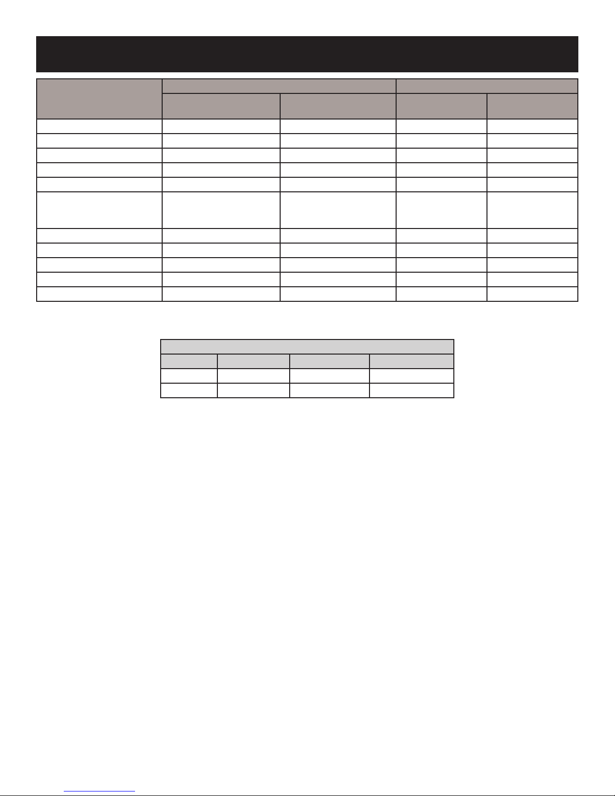
SPECIFICATIONS
NATURAL GAS LP
PENINSULA
MODELS
Input BTU/Hr Maximum 34,000 34,000 32,000 32,000
Input BTU/Hr Minimum 23,000 23,000 26,500 26,500
KWH (Maximum) 9.96 9.96 9.38 9.38
KWH (Minimum) 6.74 6.74 7.76 7.76
Orice #33 #33 #51 #51
3/16in
Air Shutter Opening*
Height without standoff 39-1/2in 39-1/2in 39-1/2in 39-1/2in
Width 42-1/4in 45-1/2in 42-1/4in 45-1/2in
Depth 24in 24in 24in 24in
Gas Inlet Shutoff Valve (pipe) 1/2 NPT 1/2 NPT 1/2 NPT 1/2 NPT
Venting 5” x 8”, See Page 26 5” x 8”, See Page 26 5” x 8”, See Page 26 5” x 8”, See Page 26
*NOTICE: Air shutter settings are factory minimum settings. Some venting congurations may require minor air shutter adjustments for
optimum performance.
(1/8in w/40ft. Vertical Vent,
ue restrictor installed)
GAS SUPPLY PRESSURES
GAS TYPE MAXIMUM MINIMUM MANIFOLD
NAT 14 4.5 3.5
LP 14 11 10
(1/8in w/40ft. Vertical Vent,
SEE-THRU
MODELS
3/16in
ue restrictor installed)
PENINSULA
MODELS
FULLY OPEN FULLY OPEN
SEE-THRU
MODELS
36092-2-0316Page 6
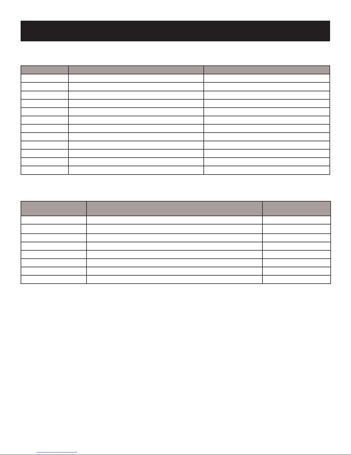
ACCESSORIES
The following accessory parts can be obtained from your Empire Comfort Systems dealer. Contact your Empire Dealer for more
accessory options. If you need additional information, contact Empire Comfort Systems Inc., 918 Freeburg Ave., Belleville, Illinois
62220-2623.
Model Number Description May Be Used On
**DVP36PRB Rustic Brick Liner - “Soldier Course” Peninsula & See-Thru Models
**DVP36PFLKR Vertical Fluted Black Liner Peninsula & See-Thru Models
**DVP36PKR Porcelain Black Liner Peninsula & See-Thru Models
FBB14 Blower Kit Peninsula & See-Thru Models
LK7 Light Kit Peninsula & See-Thru Models
*LSU24SPF Campre Log Set Peninsula & See-Thru Models
*DG36MX Rustic Decorative Boulders Peninsula & See-Thru Models
DF362PNB 1.5in. Beveled Window Frame, Brushed Nickel Peninsula & See-Thru Models
DF242NB 1.5in. Beveled Window Frame End, Brushed Nickel Peninsula Models Only
DF362PBZ 1.5in. Beveled Window Frame - Oil Rubbed Bronze Peninsula & See-Thru Models
DF242BZ 1.5in. Beveled Window Frame End - Oil Rubbed Bronze Peninsula Models Only
DVD36PBLNB Decorative Contemporary Doors - Brushed Nickel Peninsula & See-Thru Models
* Fireplace requires a log set or mixed logs and stones kit.
** Liners are not required. To add liners, order two liners for See-Through models; One for Peninsula.
Remote Control Options
& Accessories
FRBC Millivolt Battery Remote ON/OFF DVCP36(PP,SP)(3,7)
FRBTC Millivolt Battery Remote Thermostat DVCP36(PP,SP)(3,7)
TMW Millivolt Wireless Wall Thermostat DVCP36(PP,SP)(3,7)
TRW Millivot Reed Switch Wall Thermostat DVCP36(PP,SP)(3,7)
FWS-1 Direct Ignition/Millivolt Wall Switch DVCP36(PP,SP)(3,7)
FRBTP Battery Operated Remote Control with Programmable Thermostat DVCP36(PP,SP)(3,7)
RVKN-1 Remote Kit, NAT (Stepper Motor) DVCP36(PP,SP)70(N,P)
RVKP-1 Remote Kit, LP (Stepper Motor) DVCP36(PP,SP)70(N,P)
Description Models Used On
36092-2-0316 Page 7
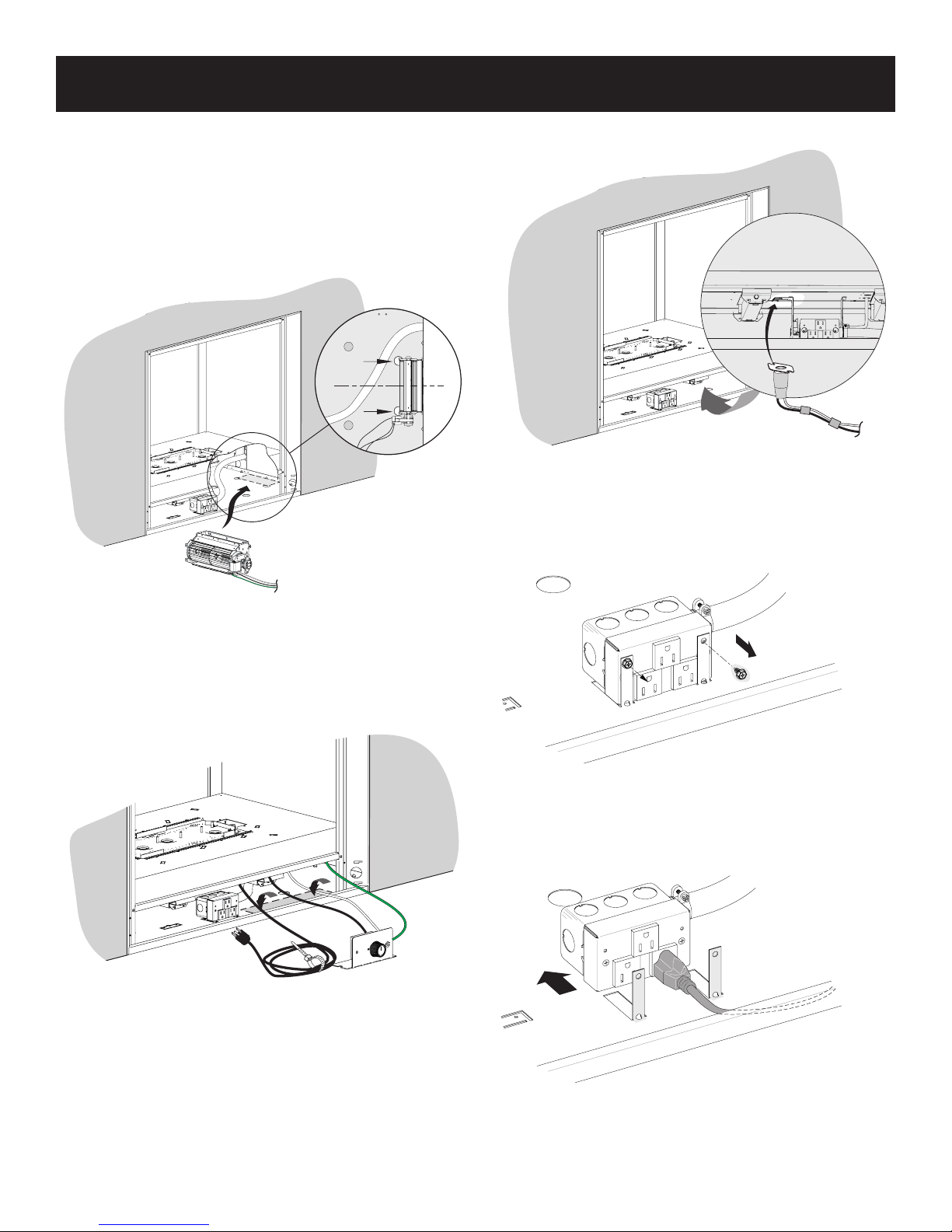
BLOWER INSTALLATION
1. Remove the glass and screen frames, and the bottom
access panel from the side which is opposite the valve.
The glass and screen frame may be removed as a unit. It is
not necessary to separate the screen frame from the glass
frame.
2. Hold the blower assembly so that the magnets are on your
right side, and insert it into the replace through the opening
to the right of the junction box. See Figure 1.
5. Snap the fan control disc into the forked prongs on the valve
bracket. See Figure 3.
Figure 3
6. If more than one receptical is necessary in order to complete
the installation, unscrew the junction box from the locating
tabs so that it can be moved rearwards and plug the blower
cord into one of the two bottom recepticals. See Figures 4
and 5.
Figure 1
3. Attach the magnet-side of the blower assembly to the outer
wall of the replace, and center it inside the replace using
the two holes in the oor as a visual guide. See Figure 1.
4. Set the rheostat control on the replace oor, with the
rheostat bracket situated as far to the right as possible. See
Figure 2.
Figure 2
Figure 4
Figure 5
7. Re-attach the junction box to the locating tabs.
8. Re-install the glass and screen frames, and the access
panel.
36092-2-0316Page 8
2
1
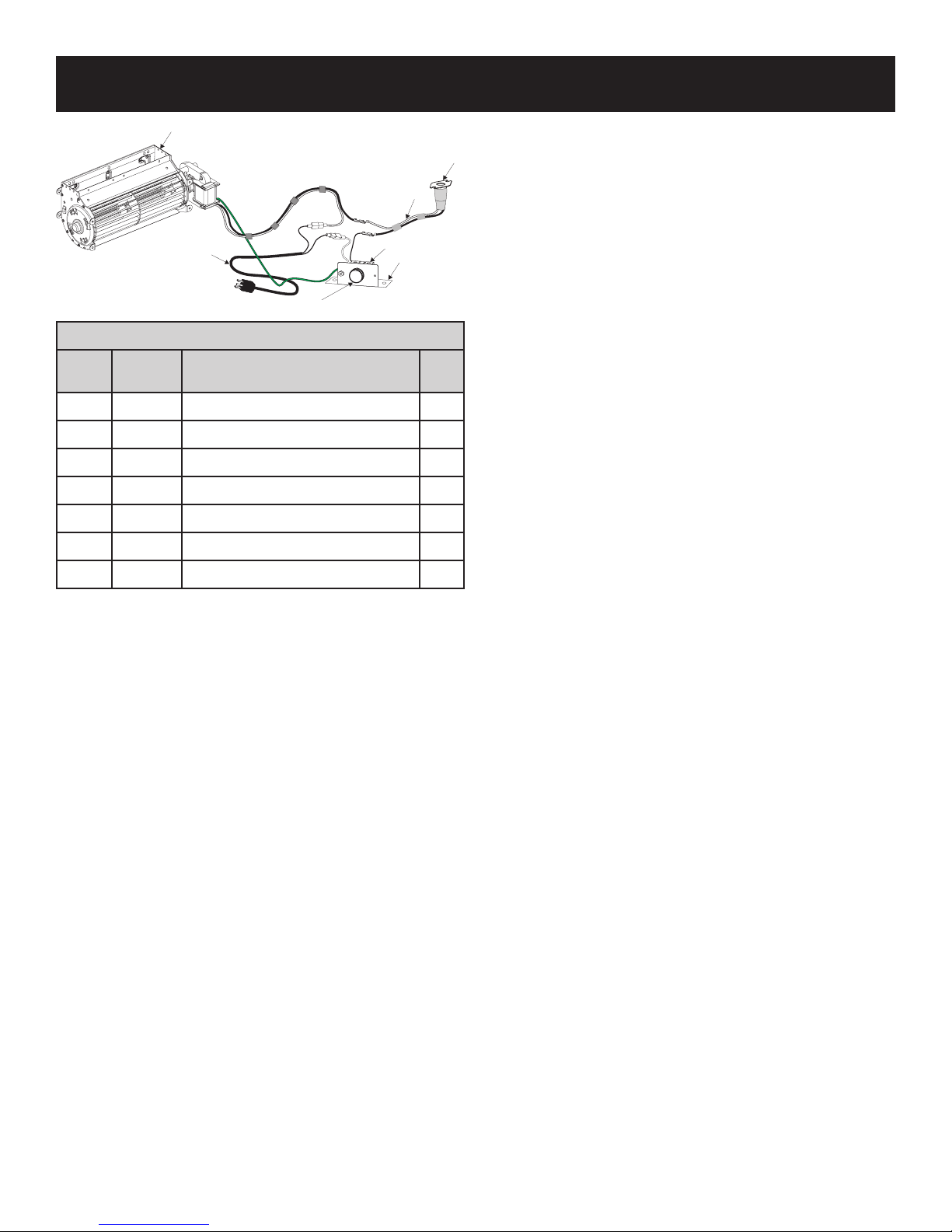
BLOWER INSTALLATION
7
3
4
BLOWER ASSEMBLY PARTS LIST
INDEX
NO.
1 36118 BLOWER ASSEMBLY 1
2 R7649 FAN, CONTROL L120-20 1
3 R3529 CORD SET, 30 INCHES 1
4 R4192 RHEOSTAT, KNOB 1
5 R4186 RHEOSTAT, 3.0 AMP 115 VAC 1
6 10088 RHEOSTAT BOX BRACKET 1
7 R11768 WIRE HARNESS, FAN CONTROL 1
PART
NO
DESCRIPTION QTY
5
6
36092-2-0316 Page 9
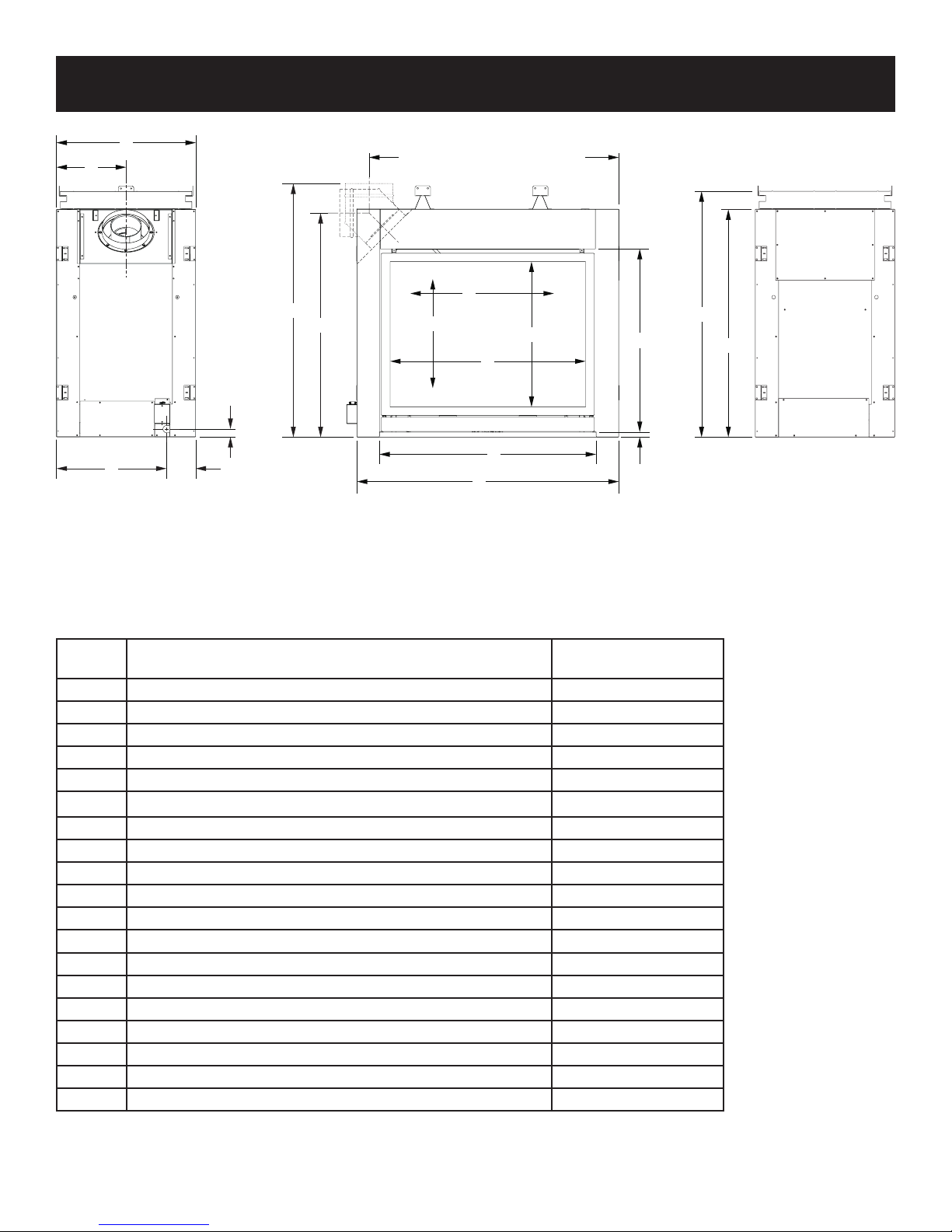
FIREPLACE DIMENSIONS - SEE-THRU
C
J
(TO CENTER OF VERTICALLY
ORIENTED ELBOW)
I
O
S
R
N
V
D
H
A
U
K
E
M
L
B
Q
INDEX
LETTER
A The maximum height of rebox face (excluding standoffs) 39-1/4
B The maximum width of the rebox face (excluding nailing anges) 45
C The maximum depth of the rebox 24
D The height of the rebox opening 31-1/2
E The width of the rebox opening 37-1/4
F The interior depth of the rebox (not shown)
H The height to the rebox standoffs 42-3/8
I Width from the left side of the box to the centerline of vertical vent 48-5/8
J Depth from back of box to centerline of vent 12
K Height from the bottom of the box to the gas line opening 1-3/8
L Depth from the front of the box to gas line opening 5
M Depth from rear of box to gas line opening 19
N* Glass height 25-3/8
O* Glass width 31
Q Distance from oor to replace opening 7/8
R Height from oor to vent collar center line - Horizontal 39-1/2
S Height from oor to vent collar - Vertical 44
U Screen opening width 33-5/8
V Screen opening height 25
*These dimensions are to the inside edges of the glass frame opening.
DIMENSION DESCRIPTION
DVCP36SP(30,70)
(Dimensions in Inches)
20-1/4
36092-2-0316Page 10
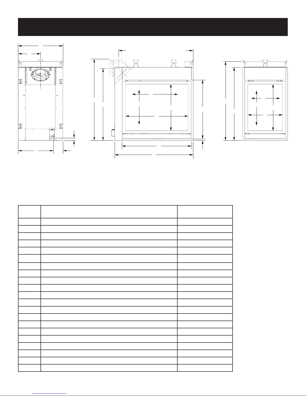
FIREPLACE DIMENSIONS - PENINSULA
C
J
(TO CENTER OF VERTICALLY-
ORIENTED ELBOW)
I
O
S
R
N
V
D
H
A
U
T
N
V
X
K
E
M
L
B
Q
INDEX
LETTER
A The maximum height of rebox face (excluding standoffs) 39-1/4
B The maximum width of the rebox face (excluding nailing anges) 42
C The maximum depth of the rebox 24
D The height of the rebox opening 31-1/2
E The width of the rebox opening 37-1/4
F The interior depth of the rebox (not shown)
H The height to the rebox standoffs 42-3/8
I Width from the left side of the box to the centerline of vent 45-5/8
J Depth from back of box to centerline of vent 12
K Height from the bottom of the box to the gas line opening 1-3/8
L Depth from the front of the box to gas line opening 5
M Depth from rear of box to gas line opening 19
N* Glass height 25-3/8
O* Glass width 31
Q Distance from oor to replace opening 7/8
R Height from oor to vent collar - Horizontal 39-1/2
S Height from oor to vent collar - Vertical 44
T* Glass width - small 16
U Screen opening width 33-5/8
V Screen opening height 25
X Screen opening width - small 18-5/8
*These dimensions are to the inside edges of the glass frame opening.
36092-2-0316 Page 11
DIMENSION DESCRIPTION
DVCP36PP(30,70)
(Dimensions in Inches)
20-1/4
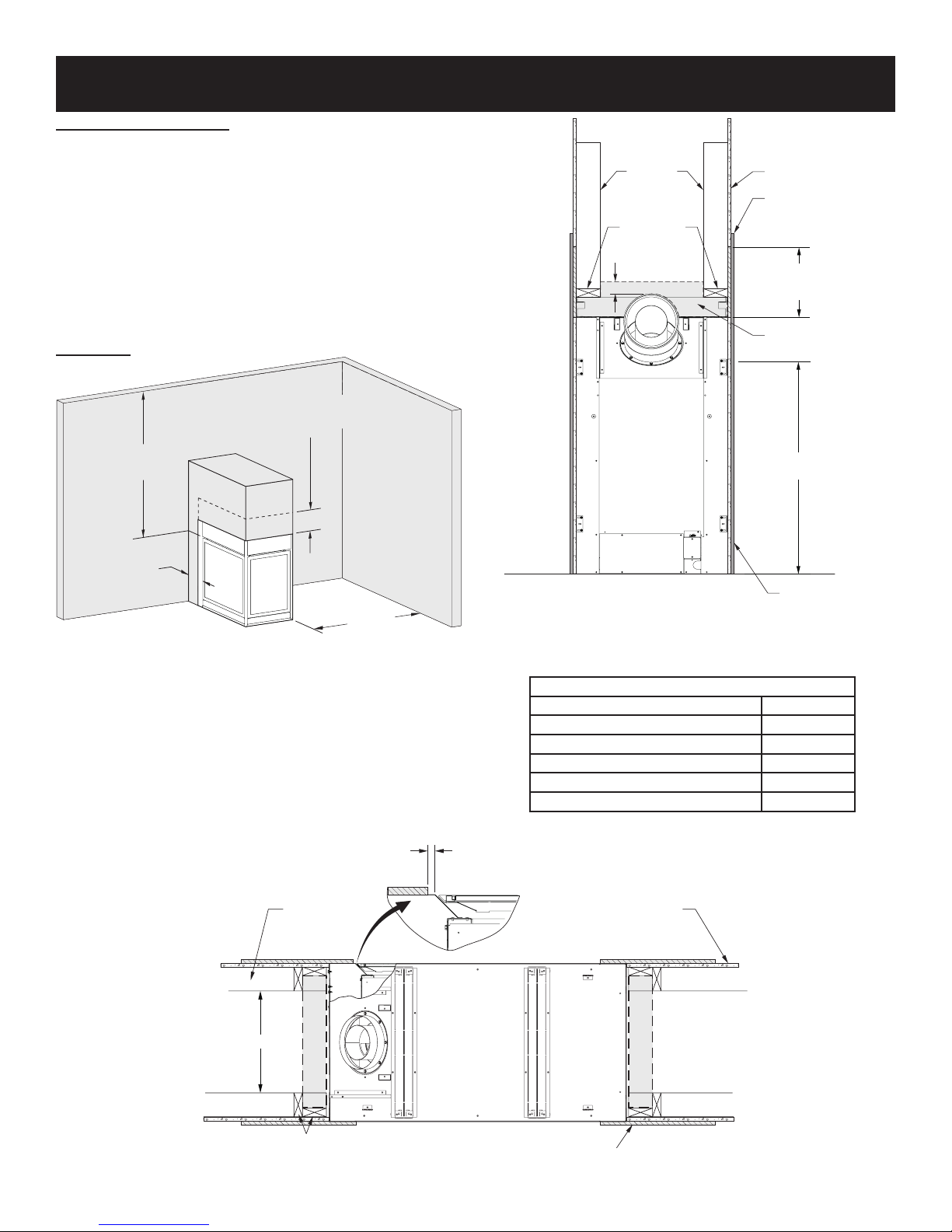
CLEARANCES
40”
TO FIREPLACE
OPENING (MIN.)
6”
TO FIREPLACE
OPENING (MIN.)
36” (MIN.)
NON-COMBUSTIBLE
BOARD, TO 16” ABOVE
FIREPLACE FACE
STUD AGAINST THE FIREPLACE
Television Considerations
Installing a television above a replace has become increasingly
popular; however, the area above any replace gets hot and most
TV manufacturers recommend against placing their products
near a heat source.
If you install a television above this replace, Empire Comfort
Systems accepts no responsibility for damage or injuries. Follow
the television manufacturer’s installation instructions, including
any recommendations regarding proximity to heat sources.
If you have a TV above your replace, turn off the replace and
let it cool completely before servicing or touching any buttons on
the TV.
Clearances
VERTICAL
FRAMING
HORIZONTAL
FRAMING
3” ABOVE
VENT
FINISHED
WALL
NON-COMBUSTIBLE
WALL COVERING
(COVER SEAM)
16” NON-COMBUSTIBLE
BOARD HEIGHT - ALL
VISIBLE SIDES
NON-COMBUSTIBLE
ZONE
FIREPLACE
OPENING
NOTICE: Dimensions apply to both See-Thru and Peninsula
models.
Figure 6 - Peninsula
FRAMING
ON FLOOR
NON-COMBUSTIBLE
20”
ZONE
NOTICE A: See Figure 9 for maximum mantel depth and
minimum height above replace.
Figure 7
Clearance to Combustibles
Back 0in
Sides Near Face (See Figure 8) 0in
Floor 0in
Top Stand-off 0in
Outer Top to Framing 3in
Above Vent 3in
LEAVE SPACE BETWEEEN
WALL COVERING AND
FIREPLACE OPENING FOR
BEAD OF CAULK
FINISHED
WALL
NON-COMBUSTIBLE
ZONE
NON-COMBUSTIBLE
WALL COVERING
VERTICAL FRAMING:
NOTE ORIENTATION OF
Figure 8
NON-COMBUSTIBLE
WALL COVERING
36092-2-0316Page 12
Mantel Chart
X
CLEARANCES
TO TOPOF
FIREPLACE
OPENING
INDEX
LETTER
MANTEL
A
B
C
Y
COMBUSTIBLE
MUST COVER
THE SURFACE
D
E
F
NON-
FINISH
MATERIAL
OF THE
FIREPLACE
FACE
Y - DISTANCE FROM
FIREPLACE OPENING
(Dimensions in Inches)
COMBUSTIBLE TRIM
AND MANTELS
ALLOWED IN
SHADED AREA
SEAM BETWEEN
NON-COMBUSTIBLE
BOARD AND DRYWALL
16”NON-COMBUSTIBLE
BOARD HEIGHT - ALL
VISIBLE SIDES OF UNIT.
X - DISTANCE FROM
FINISHED WALL
A 26 12
B 24 8
C 22 6
D 20 4-1/2
E 18 2-1/4
F 16 0
Figure 9
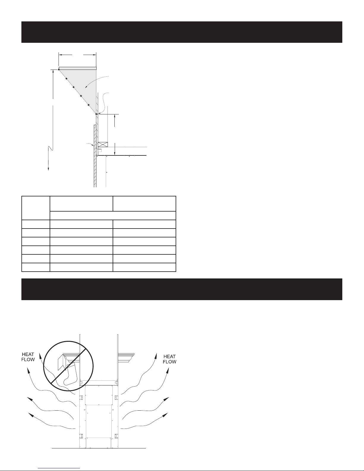
COMBUSTIBLE MATERIAL
Do not attach combustible material to the mantel of your
replace. This is a re hazard. No greeting card, stockings or
ornamentation of any type should be placed on or attached to the
replace. This is a heating replace. The ow of heat can ignite
combustibles.
36092-2-0316 Page 13
Figure 10
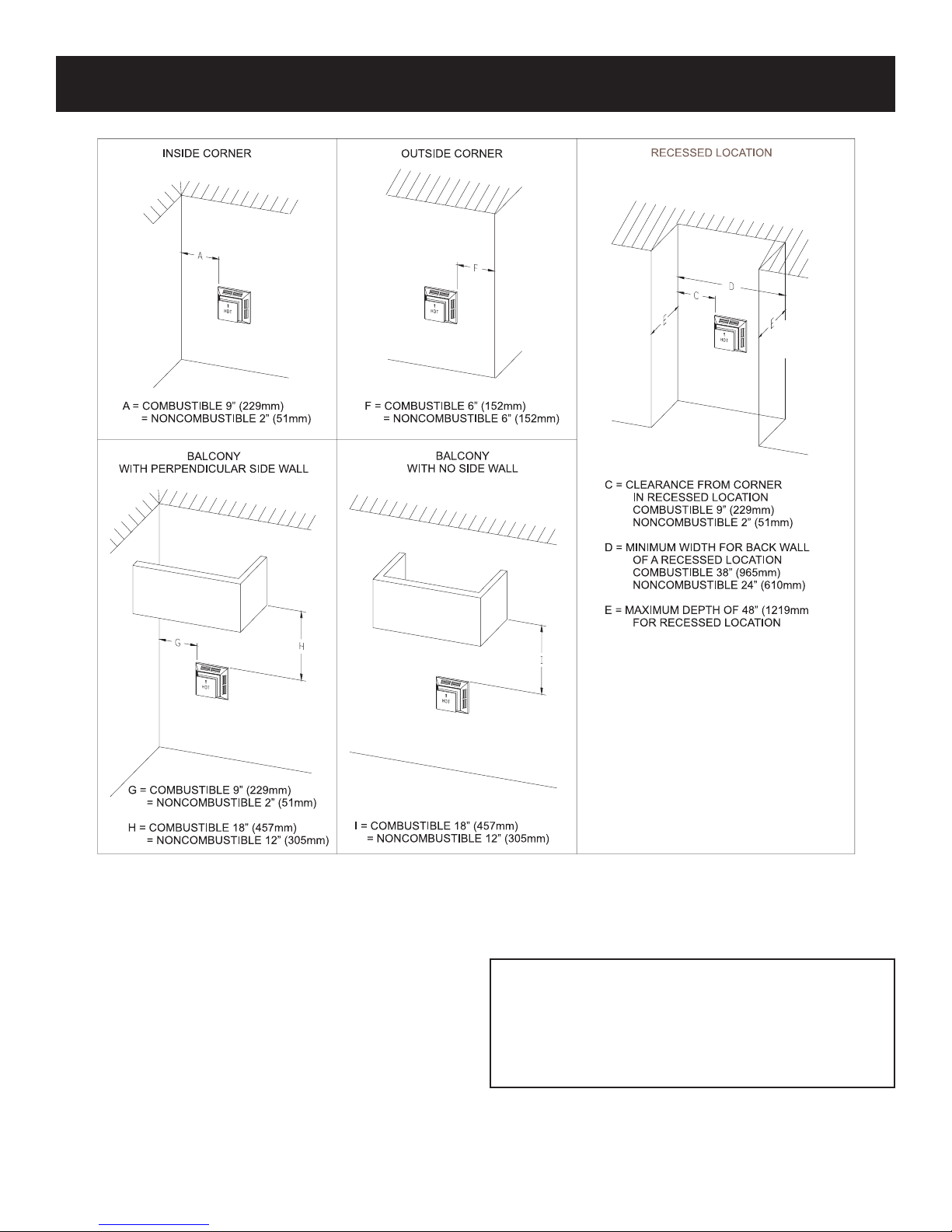
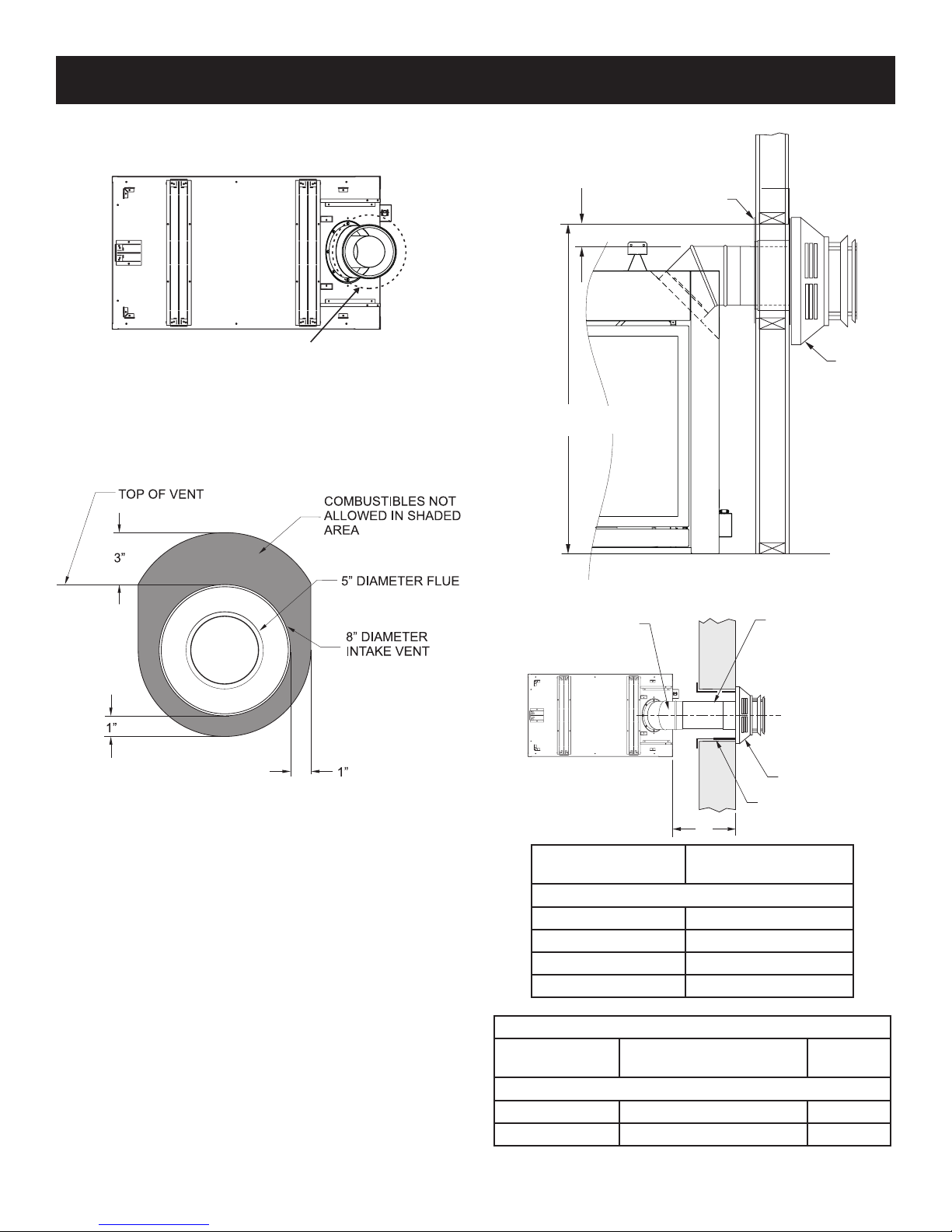
VENT TERMINATION CLEARANCES
Termination clearance for buildings with combustible and noncombustible exteriors.
Vertical Sidewall Installations
Important! Minimum clearance between vent pipes and
combustible materials is 3 inch on top, and 1 inch on bottom and
sides.
Important! When vent termination exits through foundation less
than 20 inch below siding outcrop, the vent pipe must extend
outward so that the horizontal vent termination is located ush to,
or beyond the outcrop siding.
Information on Various Venting Routes and Components
Important: It is always best to locate the replace in such a way
that minimizes the number of offsets and horizontal vent length.
Since it is very important that the venting system maintain its
balance between the combustion air intake and the ue gas
exhaust, certain limitations as to vent congurations apply and
must be strictly adhered to. See allowed vent congurations,
page 28 to 32.
Figure 11
The horizontal vent run refers to the total length of vent pipe from
the ue collar of the replace to the face of the outer wall.
Venting termination shall not be recessed into wall or siding.
ATTENTION: Vinyl Soft, Vinyl Ceiling, Vinyl Overhang
Disclaimer
Clearances are to heat resistant material (i.e. wood, metal).
This does not include vinyl. Empire Comfort Systems Inc.
will not be held responsible for heat damage caused from
terminating under vinyl overhangs, vinyl ceilings or vinyl
ventilated/unventilated softs.
36092-2-0316Page 14
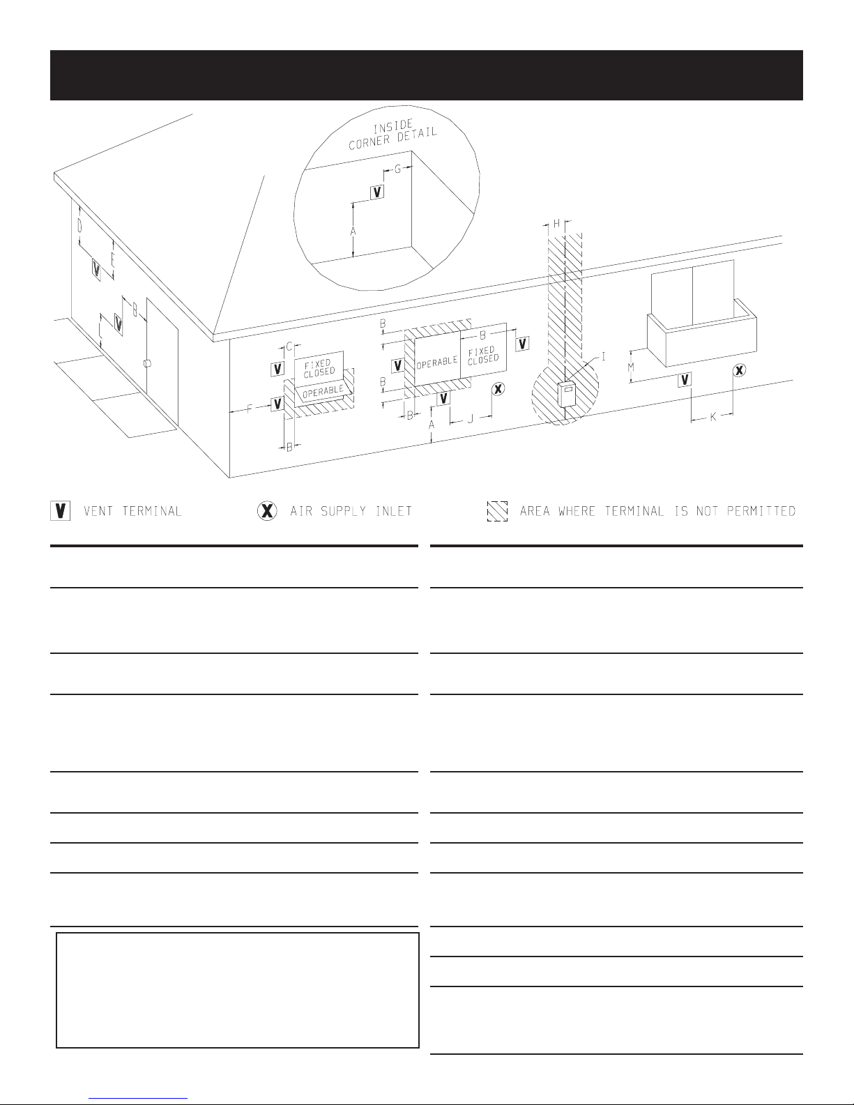
VENT TERMINATION CLEARANCES
Canadian Installations1 US Installations2 Canadian Installations1 US Installations2
A= Clearance above grade,
veranda, porch, deck, or
balcony
B= Clearance to window or
door that may be open
C= Clearance to
permanently closed
window
D= Vertical clearance
ventilated soft located
above the terminal within
a horizontal distance of 2
feet from the center line
of the terminal
E= Clearance to
unventilated soft
F= Clearance to outside
corner
G= Clearance inside corner 9 in 9 in 2
H= Clearance to each side
of center line extended
above meter/regulator
assembly
12 in 12 in
12 in 9 in
12 in 12 in
24 in 24 in
12 in 12 in
6 in 6 in 1
3 ft within a height
15 ft above the meter/
regulator assembly
3 ft †
ATTENTION: Vinyl Soft, Vinyl Ceiling, Vinyl Overhang
Disclaimer
Clearances are to heat resistant material (i.e. wood, metal).
This does not include vinyl. Empire Comfort Systems Inc.
will not be held responsible for heat damage caused from
terminating under vinyl overhangs, vinyl ceilings or vinyl
ventilated/unventilated softs.
I= Clearance to service
regulator vent outlet
J= Clearance to
nonmechanical air
supply inlet to building or
the combustion air inlet
to any other appliance
K= Clearance to a
mechanical air supply
inlet
L= Clearance above paved
sidewalk or paved
driveway located on
public property
M= Clearance under
veranda, porch deck, or
balcony
In accordance with the current CSA B149.1, Natural Gas and Propane
Installation Code
In Accordance with the current ANSI Z223.1/NFPA 54, National Fuel Gas
Code
A vent shall not terminate directly above a sidewalk or paved driveway that is
located between two single family dwellings and serves both dwellings
Permitted only if veranda,, porch, deck, or balcony is fully open on a minimum
‡
of two sides beneath the oor.
For clearances not specied in ANSI Z223.1/NFPA 54 or CSA B149.1, one of
*
the following shall be indicated:
Clearance in accordance with local installation codes and the requirements of the
gas supplier.
3 ft *
12 in 9 in
6 ft
7 ft † 7 ft
12 in ‡ 12 in
3 ft above if within 10 ft
horizontally
36092-2-0316 Page 15
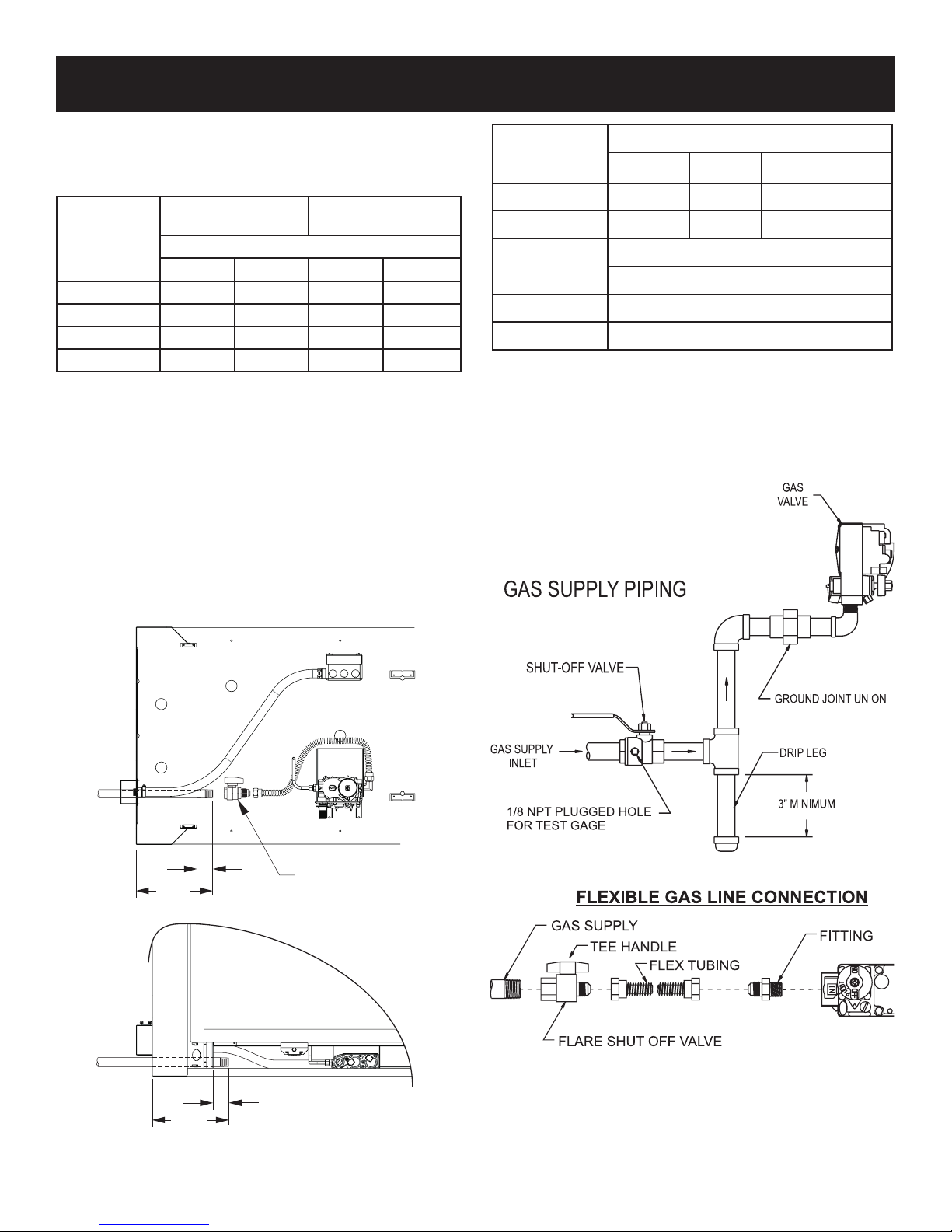
GAS SUPPLY
TOP
The gas pipeline can be brought in through the vent-end of the
replace only. Consult the current National Fuel Gas Code, ANSI
Z223.1 installation code.
RECOMMENDED GAS PIPE DIAMETER
PIPE
LENGTH
SCHEDULE 40 PIPE
INSIDE DIAMETER
(Dimensions in Inches)
TUBING, TYPE L
OUTSIDE DIAMETER
NAT LP NAT LP
0-10 feet 1/2 3/8 1/2 3/8
10-40 feet 1/2 1/2 5/8 1/2
40-100 feet 1/2 1/2 3/4 1/2
100-150 feet 3/4 1/2 7/8 3/4
NOTICE: Never use plastic pipe. Check to conrm whether your
local codes allow copper tubing or galvanized.
NOTICE: Since some municipalities have additional local codes,
it is always best to consult your local authority and installation
code.
The use of the following gas connectors is recommended:
— ANSI Z21.24 Appliance Connectors of Corrugated Metal
Tubing and Fittings.
— ANSI Z21.45 Assembled Flexible Appliance Connectors of
Other Than All-Metal Construction
The above connectors may be used if acceptable by the authority
having jurisdiction. The state of Massachusetts requires that a
exible appliance connector cannot exceed three feet in length.
GAS SUPPLY PRESSURE (INCHES W.C.)
MINIMUM NORMAL MAXIMUM
Natural Gas 4.5 7.0 14.0
LP (Propane) 10.8 11.0 14.0
Manifold Pressure (inches w.c.)
Normal (HI)
Natural Gas 3.5
LP (Propane) 10.0
A gas valve and ground joint union should be installed in the gas
line upstream of the gas control to aid in servicing. It is required
by the National Fuel Gas Code that a drip leg be installed near
the gas inlet. See Figure 13. This should consist of a vertical
length of pipe tee connected into the gas line that is capped
on the bottom in which condensation and foreign particles may
collect.
8-3/4”
8-3/4”
2”
2”
Figure 13
SHUT-OFF VALVE
INCLUDED IN
ENVELOPE PACK
FRONT
Figure 14
Figure 12
36092-2-0316Page 16
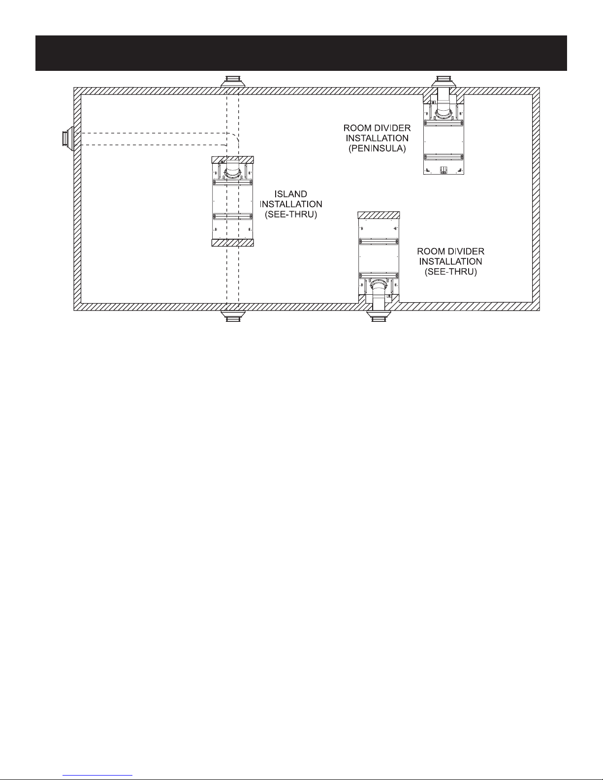
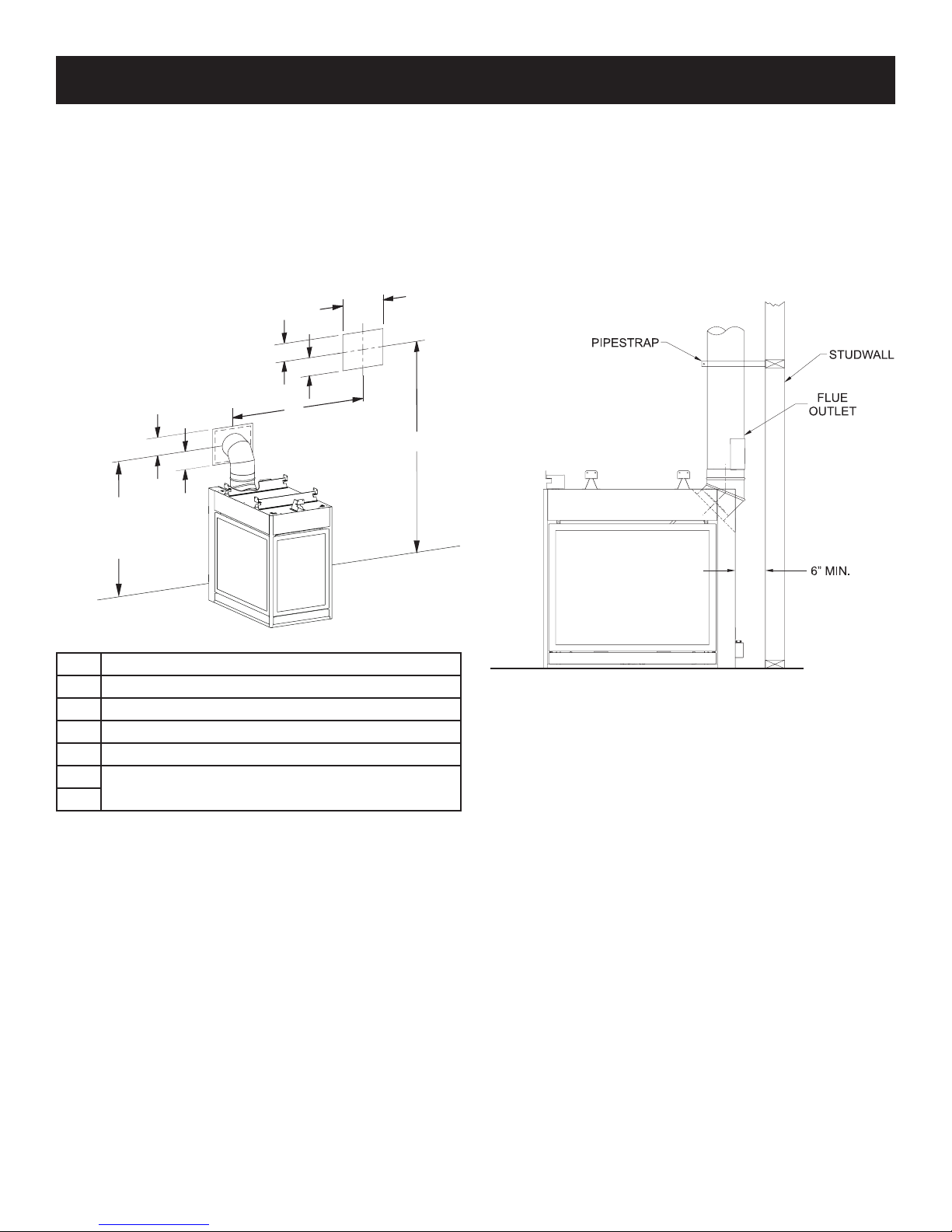
LOCATING FIREPLACE
NOTICE: Island and Room Divider installation is possible as long as the horizontal portion of the vent system does not exceed 20 feet
with a minimum vertical run of 8 feet from replace oor. See details in Venting Section.
NOTICE: Inuslate to applicable codes when installing this replace against an exterior wall.
A minimum clearance of 6 inches must be maintained from the perpendicular wall to the rebox opening of the replace, if the replace
is installed in the room divider or peninsula room divider positions.
Figure 15
36092-2-0316 Page 17
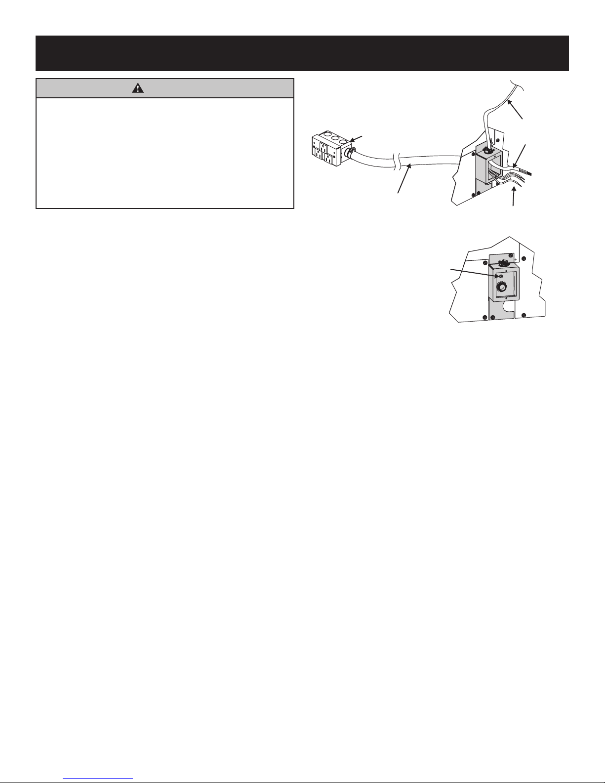
JUNCTION BOX WIRING INSTALLATION INSTRUCTIONS
POWER IN
STRANDED WIRE
WARNING
All wiring should be done by a qualied electrician
and shall be in compliance with all local, city and state
building codes. Before making the electrical connection,
make sure that main power supply is disconnected. The
replace, when installed, must be electrically grounded
in accordance with local codes or, in the absence of local
codes, with the National Electrical Code ANSI/NFPA 70
(latest edition). Improper installation of the replace can
cause serious injury or death from re, burns, explosions,
or carbon monoxide poisoning.
A factory installed junction box is located on the outside wall of the
replace on the vent side. Wiring must be fed to the junction box
and attached to the stranded wire inside with wire nuts. Connect
white to white, black to black, and ground (green stranded wire) to
the ground screw inside the junction box. See Figure 16.
RECEPTACLE BOX
INSIDE FIREPLACE
PRE-INSTALLED
CONDUIT TO
RECEPTACLE BOX
GROUND SCREW
INSIDE J-BOX
Figure 16
ELECTRIC
FROM CONDUIT
36092-2-0316Page 18
INSTALLATION
Vent Runs
In planning the installation for the replace, it is necessary to
install certain components before the replace is completely
positioned and installed. These include the direct vent system,
gas piping for the replace and the electrical wiring. Study the
“Venting Fireplace” section starting on page 25 to understand
allowable vent runs.
Positioning the Fireplace
Determine the exact position of the replace so the direct vent
termination will be centered (if possible) between two studs.
This will avoid any extra framing. All vent kit pipes should be
assembled on the replace after the replace is moved into the
nal position.
The replace can be mounted on any of the following surfaces:
1. A at hard combustible or non-combustible surface.
2. A raised platform of combustible or non-combustible material.
3. A rectangular frame constructed such that contact is made
on all four perimeter edges on the bottom of the replace (if
local codes allow).
SUPPORT SEAMS
BETWEEN DRYWALL
AND NON-COMBUSTIBLE
BOARD WITH FRAMING
C
B
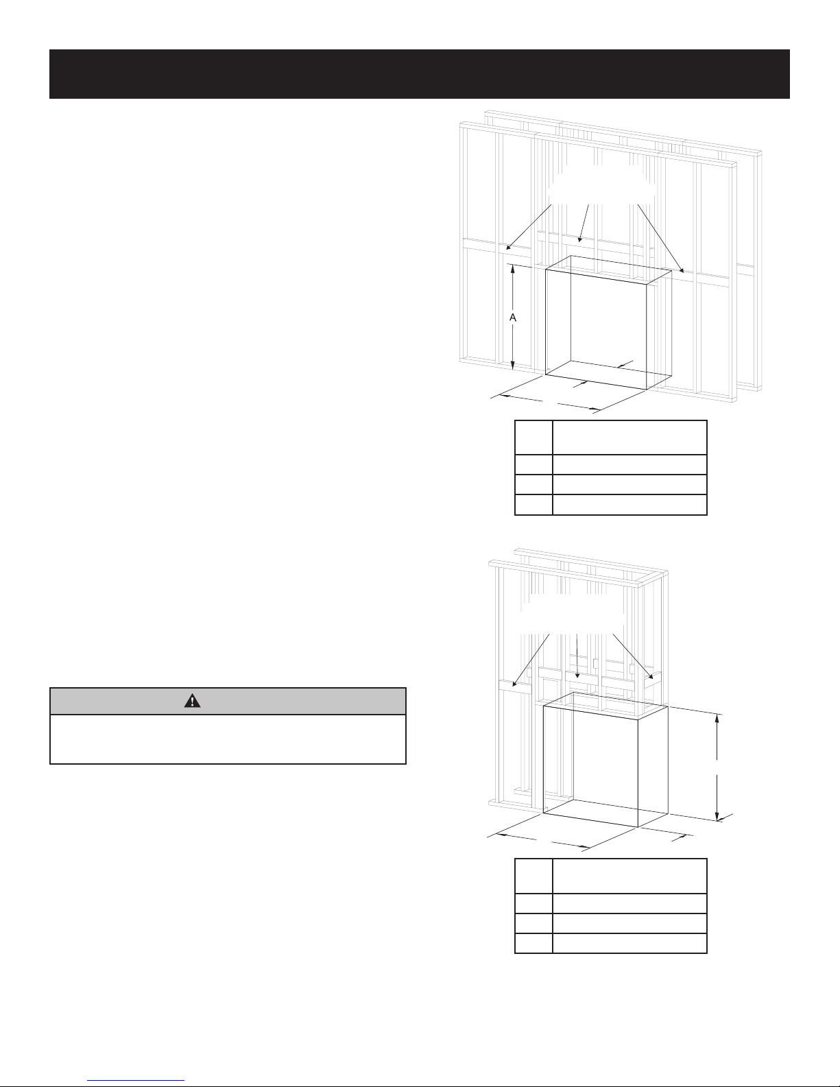
Framing
Fireplace framing can be built before or after the replace is set
in place. Framing should be positioned to accommodate wall
covering and replace facing material. The replace framing
should be constructed of 2 x 4 lumber. The framing members
may rest on the replace standoffs, however the stand-offs
are not load-bearing. Refer to Figures 17 and 18 for minimum
framing dimensions.
You may install a see-through replace in a load-bearing wall,
however the wall’s framing must include a structural header
above the replace designed to support all of the weight.
Installing a peninsula unit requires special framing techniques
above the replace to minimize the amount of weight on the
replace – especially if you plan to nish the installation with
stone or tile. This may include additional structural members in
the ceiling to support the weight.
CAUTION
To avoid unnecessary rework, measure replace
dimensions and verify framing methods, and wall covering
details before framing construction begins.
NOTICE: Framing dimension A includes a three inch clearance
for standoffs on rebox. After installing rebox into framing, the
non-combustible board will cover the three inch opening above
the rebox. See Figure 19.
DVCP36SP
(Dimensions in inches)
A 42-1/2
B 45-1/2
C 23
Figure 17 - See-Thru
SUPPORT SEAMS
BETWEEN DRYWALL
AND NON-COMBUSTIBLE
BOARD WITH FRAMING
B
A
C
36092-2-0316 Page 19
DVCP36PP
(Dimensions in inches)
A 42-1/2
B 41-3/4
C 23
Figure 18 - Peninsula
INSTALLATION
WALL COVERING
STUD AGAINST THE FIREPLACE
VERTICAL
FRAMING
HORIZONTAL
FRAMING
3” ABOVE
VENT
FINISHED
WALL
NON-COMBUSTIBLE
WALL COVERING
(COVER SEAM)
16” NON-COMBUSTIBLE
BOARD HEIGHT - ALL
VISIBLE SIDES
NON-COMBUSTIBLE
ZONE
FIREPLACE
OPENING
NON-COMBUSTIBLE
WALL COVERING
NOTICE: See Figure 9 on page 13 for maximum mantel depth
and minimum height above replace.
Figure 19
Clearance to Combustibles
Back 0in
Sides Near Face (See Figure 20) 0in
Floor 0in
Top Stand-off 0in
Outer Top to Framing 3in
Above Vent 3in
LEAVE SPACE BETWEEEN
WALL COVERING AND
FIREPLACE OPENING FOR
BEAD OF CAULK
FRAMING
ON FLOOR
NON-COMBUSTIBLE
ZONE
20”
VERTICAL FRAMING:
NOTE ORIENTATION OF
NON-COMBUSTIBLE
Figure 20
FINISHED
WALL
NON-COMBUSTIBLE
ZONE
36092-2-0316Page 20
INSTALLATION
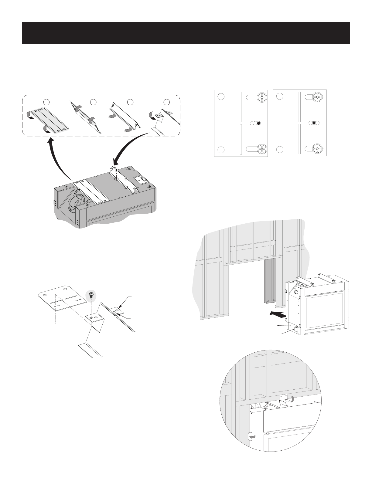
1 2 3 4
Framing
1. Before placing the replace inside the frame work, or
building the frame work around the replace, the top stand-
offs must be formed and secured. Form the top stand-offs in
the sequence shown in Figure 21, and secure them to the
rebox outer top using either four (SP) or ve (PP) screws
from your hardware pack.
STAND-OFFS SHALL
BE FORMED ON THE
UNIT. DO NOT
REMOVE.
3. If necessary, the positions of the side nailing anges can
adjusted by loosening (but do not remove) the top and
bottom screws, anchoring the bracket in place using a center
screw from the hardware pack, and re-tightening the top and
bottom screws. See Figure 23.
1/2” POSITION
Figure 23
4. After the replace has been properly positioned inside the
frame work, or the frame work has been built around the
replace, the nailing anges shall be bent 90 degrees and
the replace should be attached to the frame work using 24
(SP) or 18 (PP) drywall screws.
Temporarily remove blower access plate and tuck junction
box inside replace before setting in place. See Figure 24.
5/8” POSITION
Figure 21
2. Attach four (SP) or ve (PP) top-side nailing anges to the
top stand-offs as shown in Figure 22. Leave the nailing
anges at at this time. Note that while the non-combustible
board provided with this replace is ½” thick, some
adjustment of the nailing ange position can be made by
using either the outer or inner pair of holes.
½” OFFSET
5/8” OFFSET
Figure 22
BLOWER ACCESS PLATE
JUNCTION BOX
Figure 24
36092-2-0316 Page 21
Figure 25
INSTALLATION
WALL THIMBLE
3” MININUM CLEARANCE
TO COMBUSTIBLES
IN WALL
46-13/16”TO COMBUSTIBLES
ABOVE VENT INSIDE WALL
45°ELBOW
A
VENT CAP
WALL FIRESTOP/
THIMBLE
B
Vertical Vent Pipe Clearance
NOTICE: Need 2-inch clearance around pipe for the rst
12 inches above Firebox. See Figure 26.
2” MIN. CLEARANCE
AROUND VENT PIPE
Figure 26
Horizontal Vent Clearances
For horizontal vent, maintain a minimum 1 inch clearance
to the bottom and sides of the vent, and 3 inch clearance to
combustibles above the vent pipe. See Figure 27.
45° ELBOW WITH HORIZONTAL TERMINATION
VENT
CAP
Figure 27
Figure 28
MINIMUM PIPE
LENGTH (A)
FIREPLACE TO
EXTERIOR WALL (B)
(Dimensions in inches)
9 10-5/8
12 13-5/8
18 19-5/8
24 25-5/8
MAXIMUM REAR VENT RUN BY GAS TYPE
PIPE LENGTH
(A)
FIREPLACE TO
EXTERIOR WALL (B)
(Dimensions in inches)
84 (7ft) 84-5/8 NG
36 (3 ft) 36-5/8 LP
Figure 29
GAS TYPE
36092-2-0316Page 22
INSTALLATION
A1
CENTER OF ELBOW
STRAIGHT OUT
(MINIMUM)
A2
B
C
C
B
E
D
Cutting the Hole
After the replace has been positioned in its permanent location,
the hole through the exterior wall of the house can be cut. This
hole must be 12-5/8in high x 10-5/8in wide with its center line
determined by the amount of vertical rise and horizontal run of
the termination. See Figure 30. When locating the hole it must be
noted that the bottom of the cap must be 12in above the ground
level, and top of the cap must be no less than 18in below a
combustible projection, and no closer than 9in to any wall running
parallel to vent termination. Refer to “Below Grade Instatallation”
on page 25.
Installing Support Brackets
Install a horizontal pipe support used for each 3 feet of
horizontal run to framing members. Allow 3 inches of clearance
to combustibles above 8 inch diameter pipe and elbows and 1
inches of clearance on both sides and bottom.
Support vertical runs of this vent systems every 4 feet using
wall brackets attached to the vent pipe and secured with nails or
screws to structural framing.
NOTICE: Maintain all clearances to combustibles as shown in
Figures 6 to 8 on page 12.
DIMENSIONS (in inches)
A1 49-5/8
B 5-5/16
C 7-5/16
D 10-5/8
E See top vent conguration charts for allowable A2 and E
dimensions, pages 28 and 29.
A2
MINIMUM HOLE LOCATION DIMENSIONS FOR THROUGH
THE WALL INSTALLATIONS WITH 90 DEGREE ELBOW.
SEE FIGURE 41 ON PAGE 27 FOR PERMISSIBLE TOP VENT
HORIZONTAL AND VERTICAL DIMENSIONS.
Figure 31
Figure 30
36092-2-0316 Page 23
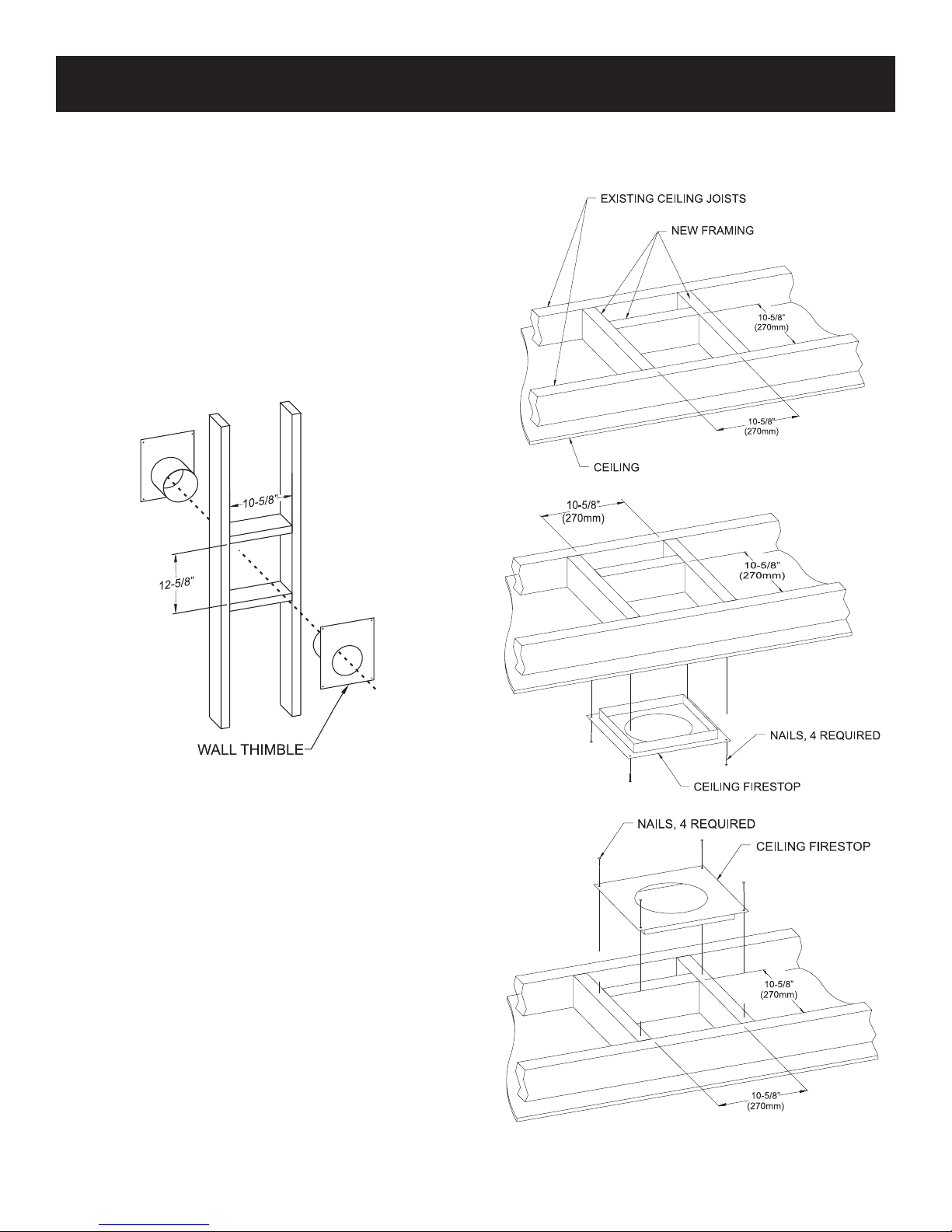
INSTALLATION
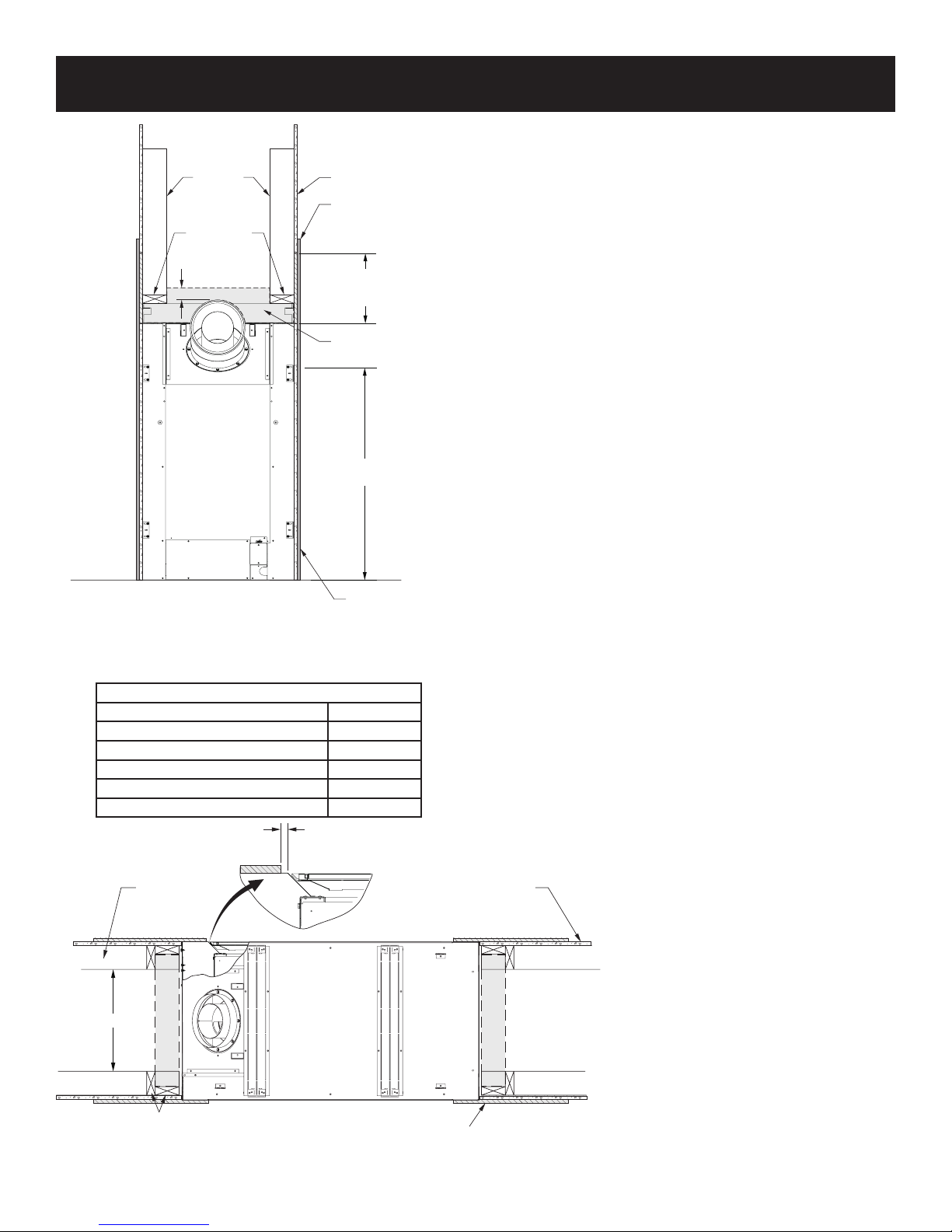
Installing Firestops
Firestops are required for safety whenever the vent system
passes through an interior wall, an exterior wall, or a ceiling.
These restops act as a rebreak heat shield and as a means
to insure that minimum clearances are maintained to the vent
system.
Horizontal Firestops
Horizontal runs in the vent system which pass through either
interior or exterior walls, require the use of wall restops on both
sides of the wall through which the vent passes.
Position the restops on both sides of the framed hole, previously
cut. Refer to Figure 32 for sizing information. Secure restop
with nails or screws. The heat shields of the restops MUST BE
placed towards the top of the hole. Continue the vent run through
the restops.
NOTICE: Remove insulation from the framed area in the attic
before installing the restop and/or vent pipes.
NOTICE: Prevent insulation from contacting pipe after it is
installed.
Figure 33
Figure 32
NOTICE: SD58DVAWTEC Wall thimble is necessary to maintain
the required three inches of clearance to combustibles above
the vent. Framed hole dimensions shown above are for this wall
thimble.
Vertical Firestops
Vertical runs of this system which pass through ceilings require
the use of ONE ceiling restop at the hole in each ceiling through
which the vent passes.
Position a plumb bob directly over the center of the vertical vent
component and mark the ceiling to establish the center point
of the vent. Drill a hole or drive a nail through this center point
and check the oor above for any obstructions such as wiring
or plumbing runs. Reposition the replace and vent system, if
necessary, to accommodate ceiling joists and/or obstructions.
Cut a 10-5/8 inch x 10-5/8 inch hole (larger if within rst 12-in
of rise) through the ceiling, using the center point previously
marked. Frame the hole with framing lumber the same size as
the ceiling joists. See Figure 33. If the area above the ceiling
is NOT an attic, position and secure the ceiling restop on the
ceiling side of the previously cut and framed hole. See Figure 34.
If the area above the ceiling is an attic, position and secure the
restop on top of the previously framed hole. See Figure 35.
Figure 34
Figure 35
36092-2-0316Page 24
 Loading...