

Empire Comfort Systems DVCP32BP30P-1, DVCP36BP32N-1, DVCP32BP32N-1, DVCP36BP30P-1, DVCP36BP32P-1 Installation Instructions And Owner's Manual
...
INSTALLATION INSTRUCTIONS
GAS-FIRED
EMPIRE
EMPIRE
Comfort Systems
AND
OWNER’S MANUAL
MODEL SERIES:
MILLIVOLT (MV)
DVCP(32,36,42)BP3(0,2)(N,P)-1
INTERMITTENT PILOT (IP)
DVCP(32,36,42)BP7(0,2)(N,P)-1
UL FILE NO. MH30033
Carton Contents
Accessory Sheet Rockwool
Hardware Pack Registration Card
Junction Box Cover Receptacle
Lava Rock
This appliance may be installed in an aftermarket,
permanently located, manufactured home (USA only)
or mobile home, where not prohibited by state or local
codes.
This appliance is only for use with the type of gas
indicated on the rating plate. This appliance is not
convertible for use with other gases, unless a certied
kit is used.
WARNING: If not installed, operated and maintained
in accordance with the manufacturer’s instructions,
this product could expose you to substances in fuel
or from fuel combustion which can cause death or
serious illness.
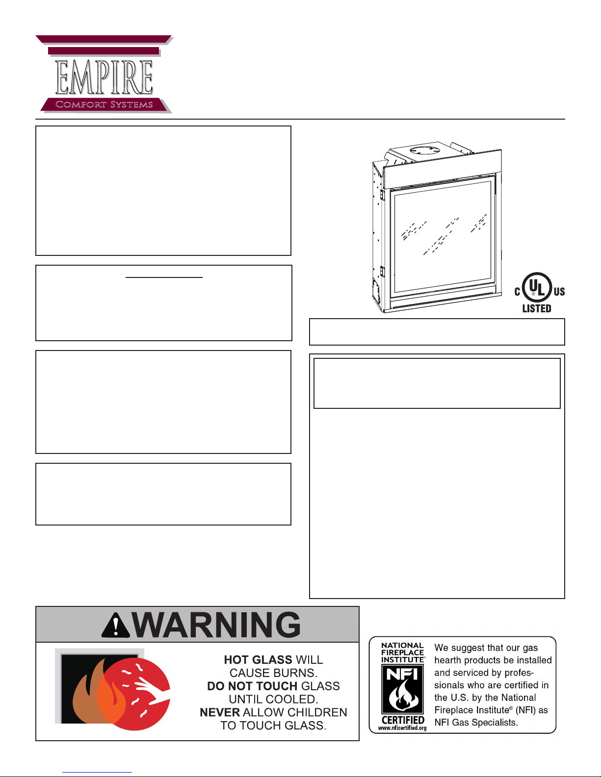
Direct Vent Zero Clearance Gas Fireplace Heater
Installer: Leave this manual with the appliance.
Consumer: Retain this manual for future reference.
WARNING: If the information in these instructions
are not followed exactly, a re or explosion may result causing property damage, personal injury or
loss of life.
— Do not store or use gasoline or other ammable
vapors and liquids in the vicinity of this or any
other appliance.
— WHAT TO DO IF YOU SMELL GAS
• Do not try to light any appliance.
• Do not touch any electrical switch; do not use
any phone in your building.
• Immediately call your gas supplier from a
neighbor’s phone. Follow the gas supplier’s
instructions.
• If you cannot reach your gas supplier, call the
re department.
— Installation and service must be performed by a
qualied installer, service agency or the gas sup-
plier.
Page 1

TABLE OF CONTENTS
SECTION PAGE
IMPORTANT SAFETY INFORMATION ......................................................................................... 3
SAFETY INFORMATION FOR USERS OF LP GAS ..................................................................... 4
REQUIREMENTS FOR MASSACHUSETTS ................................................................................ 5
INTRODUCTION ........................................................................................................................... 6
SPECIFICATIONS ......................................................................................................................... 7
ACCESSORIES ............................................................................................................................. 8
FBB10 BLOWER KIT INSTALLATION (OPTIONAL) ................................................................ 9-11
LK6 LIGHT KIT INSTALLATION (OPTIONAL) .............................................................................12
REFLECTIVE LINER KIT INSTALLATION (OPTIONAL) ............................................................. 13
CERAMIC FIBER LINER KIT INSTALLATION (OPTIONAL) ....................................................... 14
FIREPLACE SCREEN INSTALLATION (OPTIONAL) ................................................................. 15
VENT SYSTEM IDENTIFICATION .............................................................................................. 16
SPECIAL VENT SYSTEMS ......................................................................................................... 16
FIREPLACE DIMENSIONS ......................................................................................................... 17
CLEARANCES ............................................................................................................................ 18
LOCATING FIREPLACE .............................................................................................................. 19
GAS SUPPLY .............................................................................................................................. 20
INSTALLATION ....................................................................................................................... 21-24
VENTING FIREPLACE - TOP ................................................................................................25-28
EXAMPLES - TOP VENT RUN .................................................................................................... 29
VENT TERMINAL CLEARANCES ............................................................................................... 30
FRAMING AND FINISHING .................................................................................................... 31-32
TERMINATION CLEARANCES ................................................................................................... 33
VERTICAL TERMINATION ..................................................................................................... 34-35
DVVK-4F FLEX VENT INSTRUCTIONS ................................................................................36-37
MILLIVOLT OPERATING INSTRUCTIONS ................................................................................. 38
MILLIVOLT STANDING PILOT WIRING DIAGRAM .................................................................... 39
MILLIVOLT STANDING PILOT LIGHTING INSTRUCTIONS ...................................................... 40
MILLIVOLT STANDING PILOT TROUBLESHOOTING ............................................................... 41
IPI ELECTRONIC SYSTEM OPERATING INSTRUCTIONS....................................................... 42
IPI ELECTRONIC SYSTEM WIRING DIAGRAM ........................................................................ 43
INTERMITTENT PILOT LIGHTING INSTRUCTIONS .................................................................44
INTERMITTENT PILOT CONTROL SYSTEM TROUBLESHOOTING ................................... 45-47
MAINTENANCE AND SERVICE ................................................................................................. 48
MASTER PARTS DISTRIBUTOR LIST .......................................................................................49
HOW TO ORDER REPAIR PARTS .............................................................................................49
MILLIVOLT PARTS LIST - DVCP(32,36,42)BP3 .........................................................................50
MILLIVOLT PARTS VIEW - DVCP(32,36,42)BP3 .......................................................................51
IP PARTS LIST - DVCP(32,36,42)BP7 ........................................................................................ 52
IP PARTS VIEW - DVCP(32,36,42)BP7 ......................................................................................53
JUNCTION BOX WIRING INSTALLATION INSTRUCTIONS ...................................................... 54
WARRANTY ................................................................................................................................55
32261-5-0414Page 2

IMPORTANT SAFETY INFORMATION
Before enclosing the vent pipe assembly, operate the appliance to ensure it is venting properly.
DO NOT OPERATE THIS APPLIANCE WITHOUT GLASS FRONT PANEL INSTALLED
• If this appliance is installed directly on
carpeting, tile or other combustible material
other than wood ooring the appliance shall be
installed on a metal or wood panel extending
the full width and depth of the appliance.
The base referred to above does not mean the
reproof base as used on wood stoves. The
protection is for rugs that are extremely thick
and light colored tile.
• Children and adults should be alerted to the
hazards of high surface temperatures and
should stay away to avoid burns or clothing
ignition.
• Young children should be carefully supervised
when they are in the same room as the appliance.
• Due to high temperatures the appliance should
be located out of trafc and away from furniture
and draperies.
• Clothing or other ammable material should
not be placed on or near the appliance.
• Adequate accessibility clearances for servicing
and proper operation.
• This appliance must not share or be connected
to a ue serving a separate solid-fuel burning
appliance.
• Keep the area around your appliance clear
of combustible materials, gasoline and other
ammable vapor and liquids.
• Under no circumstances should any solid fuels
(wood, coal, paper or cardboard etc.) be used
in this appliance.
• The ow of combustion and ventilation air must
not be obstructed in any way.
• DO keep the appliance area clear and free
from combustible material, gasoline and other
ammable vapors and liquids.
• The glass front or any part removed for
servicing the appliance must be replaced prior
to operating the appliance. Work should be
done by a qualied service person.
• Keep burner and control compartment clean.
• Vent cap is hot while replace is in operation.
• Installation and repair should be done by a
QUALIFIED SERVICE PERSON. The appliance
should be inspected before use and at least
annually by a qualied service person. More
frequent cleaning may be required due
to excessive lint from carpeting, bedding
materials, etc. It is imperative that control
compartments, burners and circulating air
passageways of the appliance be kept clean.
• DO NOT put anything around the replace that
will obstruct the ow of ventilation air.
• Clearance in accordance with local installation
codes and the requirements of the gas supplier.
• DO examine venting system periodically and
replace damaged parts.
• DO make a periodic visual check of pilot and
burners. Clean and replace damaged parts.
• CAUTION: The glass used in your replace
is tempered glass. If the glass is cracked or
damaged in any way, it should be replaced
only with a complete glass frame assembly
from Empire. See parts list on Pages 50 - 53
for ordering.
• DO NOT use this replace if any part has been
under water. Immediately call a qualied service
technician to inspect the heater and to replace
any part of the control system and any gas
control which has been under water.
• Any safety screen or guard removed for
servicing an appliance must be replaced prior
to operating the appliance.
32261-5-0414 Page 3

SAFETY INFORMATION FOR USERS OF LP GAS
Propane (LP-Gas) is a ammable gas which can cause
res and explosions. In its natural state, propane is odorless and colorless. You may not know all the following
safety precautions which can protect both you and your
family from an accident. Read them carefully now, then
review them point by point with the members of your
household. Someday when there may not be a minute to
lose, everyone’s safety will depend on knowing exactly
what to do. If, after reading the following information,
you feel you still need more information, please contact
your gas supplier.
LP-GAS WARNING ODOR
If a gas leak happens, you should be able to smell the
gas because of the odorant put in the LP-Gas. That’s
your signal to go into immediate action!
• Do not operate electric switches, light matches, use your
phone. Do not do anything that could ignite the gas.
• Get everyone out of the building, vehicle, trailer, or area.
Do that IMMEDIATELY.
• Close all gas tank or cylinder supply valves.
• LP-Gas is heavier than air and may settle in low areas
such as basements. When you have reason to suspect
a gas leak, keep out of basements and other low areas.
Stay out until reghters declare them to be safe.
• Use your neighbor’s phone and call a trained LP-Gas
service person and the re department. Even though
you may not continue to smell gas, do not turn on the
gas again. Do not re-enter the building, vehicle, trailer,
or area.
• Finally, let the service man and reghters check for
escaped gas. Have them air out the area before you
return. Properly trained LP-Gas service people should
repair the leak, then check and relight the gas appliance
for you.
NO ODOR DETECTED - ODOR FADE
Some people cannot smell well. Some people cannot
smell the odor of the chemical put into the gas. You
must nd out if you can smell the odorant in propane.
Smoking can decrease your ability to smell. Being around an
odor for a time can affect your sensitivity or ability to detect
that odor. Sometimes other odors in the area mask the gas
odor. People may not smell the gas odor or their minds are
on something else. Thinking about smelling a gas odor can
make it easier to smell.
The odorant in LP-Gas is colorless, and it can fade
under some circumstances. For example, if there is an
underground leak, the movement of the gas through soil
can lter the odorant. Odorants in LP-Gas also are subject
to oxidation. This fading can occur if there is rust inside the
storage tank or in iron gas pipes.
The odorant in escaped gas can adsorb or absorb onto or
into walls, masonry and other materials and fabrics in a room.
That will take some of the odorant out of the gas, reducing
its odor intensity.
LP-Gas may stratify in a closed area, and the odor intensity
could vary at different levels. Since it is heavier than air, there
may be more odor at lower levels. Always be sensitive to the
slightest gas odor. If you detect any odor, treat it as a serious
leak. Immediately go into action as instructed earlier.
SOME POINTS TO REMEMBER
• Learn to recognize the odor of LP-Gas. Your local LP-
Gas Dealer can give you a “Scratch and Sniff” pamphlet.
Use it to nd out what the propane odor smells like. If
you suspect that your LP-Gas has a weak or abnormal
odor, call your LP-Gas Dealer.
• If you are not qualied, do not light pilot lights, perform
service, or make adjustments to appliances on the LPGas system. If you are qualied, consciously think about
the odor of LP-Gas prior to and while lighting pilot lights
or performing service or making adjustments.
• Sometimes a basement or a closed-up house has a musty
smell that can cover up the LP-Gas odor. Do not try to
light pilot lights, perform service, or make adjustments
in an area where the conditions are such that you may
not detect the odor if there has been a leak of LP-Gas.
• Odor fade, due to oxidation by rust or adsorption on walls
of new cylinders and tanks, is possible. Therefore, people
should be particularly alert and careful when new tanks
or cylinders are placed in service. Odor fade can occur
in new tanks, or reinstalled old tanks, if they are lled
and allowed to set too long before relling. Cylinders
and tanks which have been out of service for a time may
develop internal rust which will cause odor fade. If such
conditions are suspected to exist, a periodic sniff test of
the gas is advisable. If you have any question about
the gas odor, call your LP-Gas dealer. A periodic sniff
test of the LP-Gas is a good safety measure under
any condition.
• If, at any time, you do not smell the LP-Gas odorant and
you think you should, assume you have a leak. Then take
the same immediate action recommended above for the
occasion when you do detect the odorized LP-Gas.
• If you experience a complete “gas out,” (the container
is under no vapor pressure), turn the tank valve off immediately. If the container valve is left on, the container
may draw in some air through openings such as pilot light
orices. If this occurs, some new internal rusting could
occur. If the valve is left open, then treat the container
as a new tank. Always be sure your container is under
vapor pressure by turning it off at the container before
it goes completely empty or having it relled before it is
completely empty.
32261-5-0414Page 4

REQUIREMENTS FOR MASSACHUSETTS
For all side wall horizontally vented gas fueled equipment
installed in every dwelling, building or structure used in
whole or in part for residential purposes, including those
owned or operated by the Commonwealth and where the
side wall exhaust vent termination is less than seven feet
above nished grade in the area of the venting, including but
not limited to decks and porches, the following requirements
shall be satised:
1. INSTALLATION OF CARBON MONOXIDE
DETECTORS. At the time of installation of the side wall
horizontal vented gas fueled equipment, the installing
plumber or gastter shall observe that a hard wired
carbon monoxide detector with an alarm and battery
back-up is installed on the oor level where the gas
equipment is to be installed. In addition, the installing
plumber or gastter shall observe that a battery
operated or hard wired carbon monoxide detector
with an alarm is installed on each additional level of
the dwelling, building or structure served by the side
wall horizontal vented gas fueled equipment. It shall
be the responsibility of the property owner to secure
the services of qualied licensed professionals for the
installation of hard wired carbon monoxide detectors
a. In the event that the side wall horizontally vented
gas fueled equipment is installed in a crawl space or
an attic, the hard wired carbon monoxide detector
with alarm and battery back-up may be installed on
the next adjacent oor level.
b. In the event that the requirements of this subdivision
can not be met at the time of completion of
installation, the owner shall have a period of thirty
days to comply with the above requirements;
provided, however, that during said thirty day period,
a battery operated carbon monoxide detector with
an alarm shall be installed.
2. APPROVED CARBON MONOXIDE DETECTORS.
Each carbon monoxide detector as required in
accordance with the above provisions shall comply
with NFPA 720 and be ANSI/UL 2034 listed and IAS
certied.
3. SIGNAGE. A metal or plastic identication plate shall be
permanently mounted to the exterior of the building at a
minimum height of eight feet above grade directly in line
with the exhaust vent termination for the horizontally
vented gas fueled heating appliance or equipment. The
sign shall read, in print size no less than 1/2 inch in size,
“GAS VENT DIRECTLY BELOW. KEEP CLEAR OF
ALL OBSTRUCTIONS”.
4. INSPECTION. The state or local gas inspector of the
side wall horizontally vented gas fueled equipment shall
not approve the installation unless, upon inspection,
the inspector observes carbon monoxide detectors and
signage installed in accordance with the provisions of
248 CMR 5.08(2)(a) 1 through 4.
(b) EXEMPTIONS: The following equipment is exempt
from 248 CMR 5.08(2)(a)1 through 4:
1. The equipment listed in Chapter 10 entitled
“Equipment Not Required To Be Vented” in the
most current edition of NFPA 54 as adopted by
the Board; and
2. Product Approved side wall horizontally vented
gas fueled equipment installed in a room or
structure separate from the dwelling, building or
structure used in whole or in part for residential
purposes.
(d) MANUFACTURER REQUIREMENTS - GAS
EQUIPMENT VENTING SYSTEM NOT
PROVIDED. When the manufacturer of a Product
Approved side wall horizontally vented gas fueled
equipment does not provide the parts for venting the
ue gases, but identies “special venting systems”,
the following requirements shall be satised by the
manufacturer:
1. The referenced “special venting system”
instructions shall be included with the appliance
or equipment installation instructions; and
2. The “special venting systems” shall be Product
Approved by the Board, and the instructions
for that system shall include a parts list and
detailed installation instruction.
(e) A copy of all installation instructions for all Product
Approved side wall horizontally vented gas fueled
equipment, all venting instructions, all parts lists
for venting instructions, and/or all venting design
instructions shall remain with the appliance or
equipment at the completion of the installation.
32261-5-0414 Page 5

INTRODUCTION
Instructions to Installer
1. Installer must leave instruction manual with owner after
installation.
2. Installer must have owner ll out and mail warranty card
supplied with the replace.
3. Installer should show owner how to start and operate the
replace.
This direct vent gas replace heater is designed to operate
with all combustion air being siphoned from the outside of the
building and all exhaust gases expelled to the outside of the
building. The information contained in this manual pertains to
all models and gas control systems unless otherwise noted.
Appliance Certication
Warning: This unit is not for use with solid fuels.
This replace is design certied in accordance with American
National Standard/CSA Standard ANSI Z21.88/CSA 2.33 and
by Underwriters Laboratories as a Direct Vent Gas Fireplace
Heater and shall be installed according to these instructions.
Consult your local building code agency, prior to installation,
to ensure compliance with local codes-including permits and
inspections.
The replace, when installed, must be electrically grounded
in accordance with local codes or, in absence of local codes,
with the National Electric Code ANSI/NFPA 70 or Canadian
Electric code, CSA C22.1, if an external electrical source is
utilized.
These models may be installed in a bedroom or bed-sitting
room in the U.S.A. and Canada.
Qualied Installing Agency
Installation and replacement of gas piping, gas utilization
equipment or accessories and repair and servicing of
equipment shall be performed only by a qualied agency. The
term “qualied agency” means any individual, rm, corporation
or company which either in person or through a representative
is engaged in and is responsible for (a) the installation or
replacement of gas piping or (b) the connection, installation,
repair or servicing of equipment, who is experienced in such
work, familiar with all precautions required and has complied
with all the requirements of the authority having jurisdiction.
State of Massachusetts: The installation must be made
by a licensed plumber or gas tter in the Commonwealth
of Massachusetts.
Warning: ANY CHANGE TO THIS FIREPLACE OR ITS
CONTROLS CAN BE DANGEROUS.
Improper installation or use of the replace can cause
serious injury or death from re, burns, explosions, or
carbon monoxide poisoning.
The installation must conform with local codes or, in the
absence of local codes, with the National Fuel Gas Code
ANSI Z223.1/NFPA 54* Natural Gas and Propane Installation
Code, or CSA B149.1 in Canada. *Available from the American
National Standards Institute, Inc. 11 West 42nd St., New York, N.Y. 10036.
Any alteration of the original design, installed other than
as shown in these instructions or use with a type of gas
not shown on the rating plate is the responsibility of the
person and company making the change.
Important
All correspondence should refer to complete Model Number,
Serial Number and type of gas.
High Altitude
When installing this unit at an elevation above 2000 feet (in
the United States) it may be necessary to decrease the input
rating by changing the existing burner orice to a smaller
size. Generally, input should be reduced 4 percent for each
1000 feet above sea level. However, if the heating value of
the gas has been reduced, this general rule may not apply.
Check with Empire Comfort Systems for proper orice size
identication.
Canadian High Altitude
Altitude: 0-4500 feet (0-1370 m)
When installing this unit at an elevation above 4500 feet (in
Canada), check with Empire Comfort Systems.
Consult your Empire Comfort Systems for assistance in
determining the proper orice for location.
Preparation
This direct vent gas replace and its components are tested
and safe when installed in accordance with this Installation
Manual. Report to your dealer any parts damaged in shipment,
specically check glass condition. Do not install unit with
damaged, incomplete, or substitute parts. Read all instructions
before starting installation and follow these instructions
carefully during installation to insure maximum benet and
safety. Failure to follow them will void your warranty and may
present a re hazard.
The warranty will be voided by, and the warranter disclaims
any responsibility for the following actions:
• Installation of any damaged replace or vent system
component.
• Modication of the replace or direct vent system.
• Installation other than as instructed by Empire Comfort
Systems, Inc.
• Improper positioning of the logs, glass door or decorative
rock.
• Installation and/or use of any component part not
manufactured or approved by manufacturer.
32261-5-0414Page 6
SPECIFICATIONS
DVCP32NAT DVCP32LP DVCP36NAT DVCP36LP DVCP42NAT DVCP42LP
Input BTU/Hr Maximum 24,000 22,000 26,000 24,000 28,500 26,500
Input BTU/Hr Minimum (millivolt only) 18,000 18,000 19,000 19,000 21,000 22,000
KWH (Maximum) 7.03 6.45 7.62 7.03 8.35 7.77
KWH (Minimum) 5.27 5.27 5.57 5.57 6.15 6.3
Orice 42 54 40 1.45mm 39 1.55mm
Air Shutter Opening 1/4” Full Open 1/4” Full Open 1/8” Full Open
Gas Inlet Shutoff Valve (Pipe) 1/2 NPT 1/2 NPT 1/2 NPT 1/2 NPT 1/2 NPT 1/2 NPT
NOTE: Air shutter settings are factory minimum settings. Some venting congurations may require minor air shutter adjustments for
optimum performance.
GAS SUPPLY PRESSURES
GAS TYPE MAXIMUM MINIMUM MANIFOLD
NAT 14.0” 4.5” 3.5”
LP 14.0” 10.8” 10.0”
Remote Control Options
& Accessories
FRBC Millivolt Battery Remote ON/OFF DVCP(32,36,42)BP(3,7)
FRBTC Millivolt Battery Remote Thermostat DVCP(32,36,42)BP(3,7)
TMW Millivolt Wireless Wall Thermostat DVCP(32,36,42)BP(3,7)
TRW Millivolt Reed Switch Wall Thermostat DVCP(32,36,42)BP(3,7)
FWS-1 Direct Ignition/Millivolt Wall Switch DVCP(32,36,42)BP(3,7)
FRBTP Battery Operated Remote Control with Programmable Thermostat DVCP(32,36,42)BP(3,7)
RVKN-1 Remote Kit, NAT (Stepper Motor) DVCP(32,36,42)BP7N
RVKP-1 Remote Kit, LP (Stepper Motor) DVCP(32,36,42)BP7p
Venting Options Description
DVVK-4TSP
(DVVK-4TS)
DVVK-4TP
(DVVK-4T)
DVVK-4VP
(DVVK-4V)
DVVK-4F Horizontal ex vent kit (4' FLEX)
SD46DVA-FCFX7 Flex Adaptor Collar (must be used with ex kits)
Description Models Used On
Top vent kit (horizontal) - 4½" to 6" (114.3 mm to 152 mm) wall thickness
Top vent kit (horizontal) - 8" to 12" (203 mm to 305 mm) wall thickness
Vertical vent kit
32261-5-0414 Page 7
ACCESSORIES
The following accessory parts can be obtained from your Empire Comfort Systems dealer. If you need additional information
beyond what your dealer can furnish, contact Empire Comfort Systems Inc., 918 Freeburg Ave., Belleville, Illinois 62220-
2623.
Model Number Description
DVFS32MBL Fireplace Screen, 32, Matte Black
DVFS36MBL Fireplace Screen, 36, Matte Black
DVFS42MBL Fireplace Screen, 42, Matte Black
DVP32TAB Liner, Aged Brick, Ceramic Fiber
DVP32TCB Liner, Cottage Brick, Ceramic Fiber
DVP32TKR Liner, Black Reective
DVP32TRB Liner, Rustic Brick, Ceramic Fiber
DVP36TAB Liner, Aged Brick, Ceramic Fiber
DVP36TCB Liner, Cottage Brick, Ceramic Fiber
DVP36TKR Liner, Black Reective
DVP36TRB Liner, Rustic Brick, Ceramic Fiber
DVP42TAB Liner, Aged Brick, Ceramic Fiber
DVP42TCB Liner, Cottage Brick, Ceramic Fiber
DVP42TKR Liner, Traditional Black Reective
DVP42TRB Liner, Rustic Brick, Ceramic Fiber
FBB10 Blower, Auto Variable-Speed
LK6 Lighting Kit, 120 V
Attention: This unit requires Ceramic Fiber Logs to complete the replace interior. Contact your Empire Comfort
Systems Dealer (see Page 49) for further information. Do not operate the replace without the decorative acces-
sory installed.
32261-5-0414Page 8
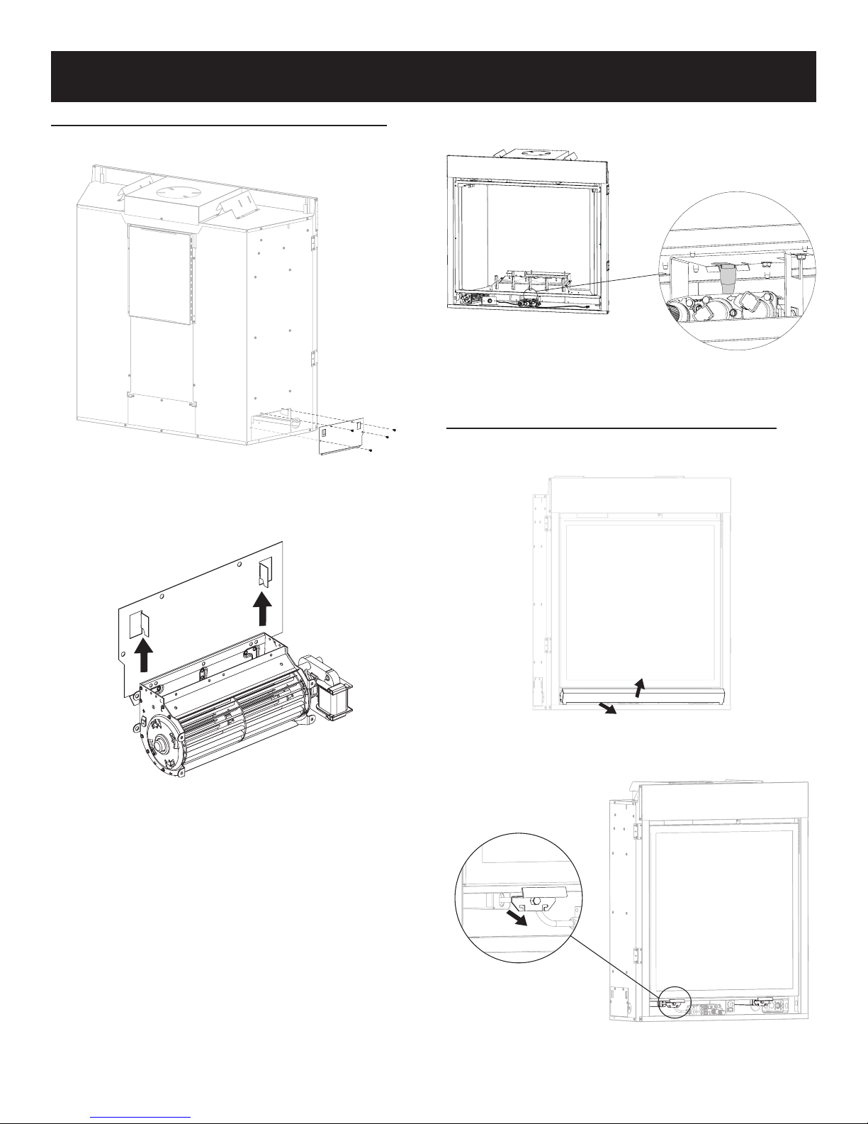
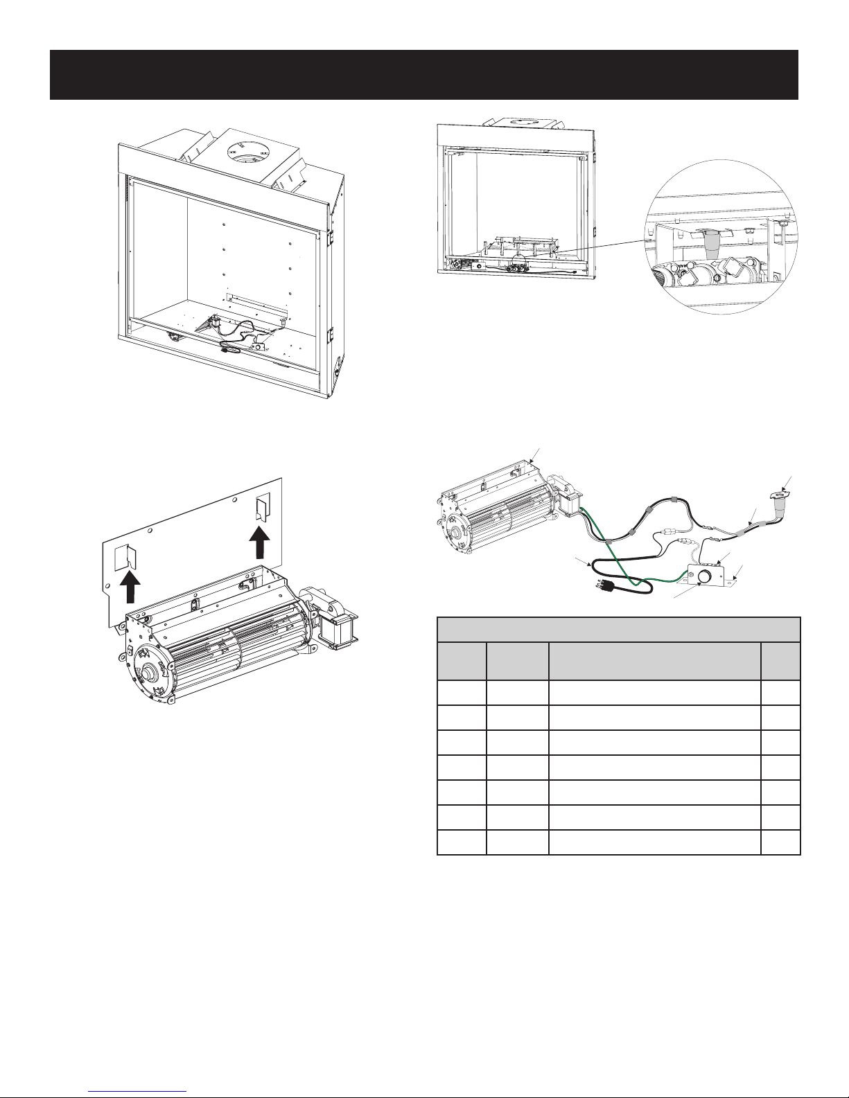
FBB10 BLOWER KIT INSTALLATION (OPTIONAL)
BENCH INSTALLATION (BEFORE INSTALLED IN WALL)
1. With Power completely turned off, Remove plate and four
screws from right panel. See Figure 1.
Figure 1
2. Install the blower onto the prebent brackets on the blower
plate. Ensure the Velcro connects to secure the blower in
place. See Figure 2.
5. Install thermo disc by snapping into valve bracket
burner assembly. See Figure 3.
Figure 3
6. Connect Power source into outlet.
BLOWER INSTALLATION (AFTER INSTALLED IN WALL)
1. Make sure power is turned off prior to any removal. Lift and
pull panel to remove from bottom assembly. See Figure 4.
Figure 2
3. Route wiring through opening.
4. Secure blower assembly into place per step 2 with velcro.
32261-5-0414 Page 9
Figure 4
2. Undo two latches at bottom of rebox assembly. See Figure
5.
Figure 5
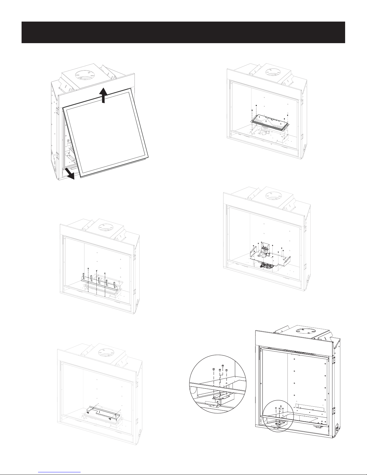
FBB10 BLOWER KIT INSTALLATION (OPTIONAL)
3. Disengage Glass Frame by pulling in upward swinging
position. See Figure 6.
Figure 6
4. Remove grate by disassembling and removing the three
screws on top panel. See Figure 7.
6. Remove the four screws securing burner and slide to right
then lift burner off. See Figure 9.
Figure 9
7. Remove seven screws and lift burner assembly. See Figure
10.
Figure 7
5. Remove log support by removing the two screws securing the
metal plate to log support. See Figure 8.
Figure 8
Figure 10
8. Remove the four #10 x 1/2 screws securing the latch assem-
bly to the underside of the rebox and set aside. See Figure
11.
Figure 11
32261-5-0414Page 10
FBB10 BLOWER KIT INSTALLATION (OPTIONAL)
2
9. Install blower through rebox cutout. See Figure 12.
Figure 12
Figure 14
17. Connect Power source into outlet.
18. Reinstall the glass frame removed in step 3. See Figure 6.
19. Reconnect the latches at the bottom of the rebox assembly.
See Figure 5.
20. Replace bottom assembly removed in step 1. See Figure 4.
10. Install the blower onto the prebent brackets on the blower
plate. Ensure the Velcro connects to secure the blower in
place. See Figure 13.
Figure 13
11. Reinstall the latch assembly removed in step 8. See Figure
11.
12. Reinstall the burner assembly and seven screws removed in
step 7. See Figure 10.
13. Reinstall the burner and four screws removed in step 6. See
Figure 9.
14. Reinstall the log support and secure it with the metal plate and
two screws removed in step 5. See Figure 8.
15. Reinstall the grate three screws removed in step 4. See Fig-
ure 7.
16. Install thermo disc by snapping into valve bracket burner assembly. See Figure 14.
1
3
4
BLOWER ASSEMBLY PARTS LIST
INDEX
NO.
1 R2804 BLOWER ASSEMBLY 1
2 R7649 FAN, CONTROL L120-20 1
3 R3529 CORD SET, 30 INCHES 1
4 R4192 RHEOSTAT, KNOB 1
5 R4186 RHEOSTAT, 3.0 AMP 115 VAC 1
6 10088 RHEOSTAT BOX BRACKET 1
7 R11768 WIRE HARNESS, FAN CONTROL 1
PART
NO
DESCRIPTION QTY
5
7
6
32261-5-0414 Page 11
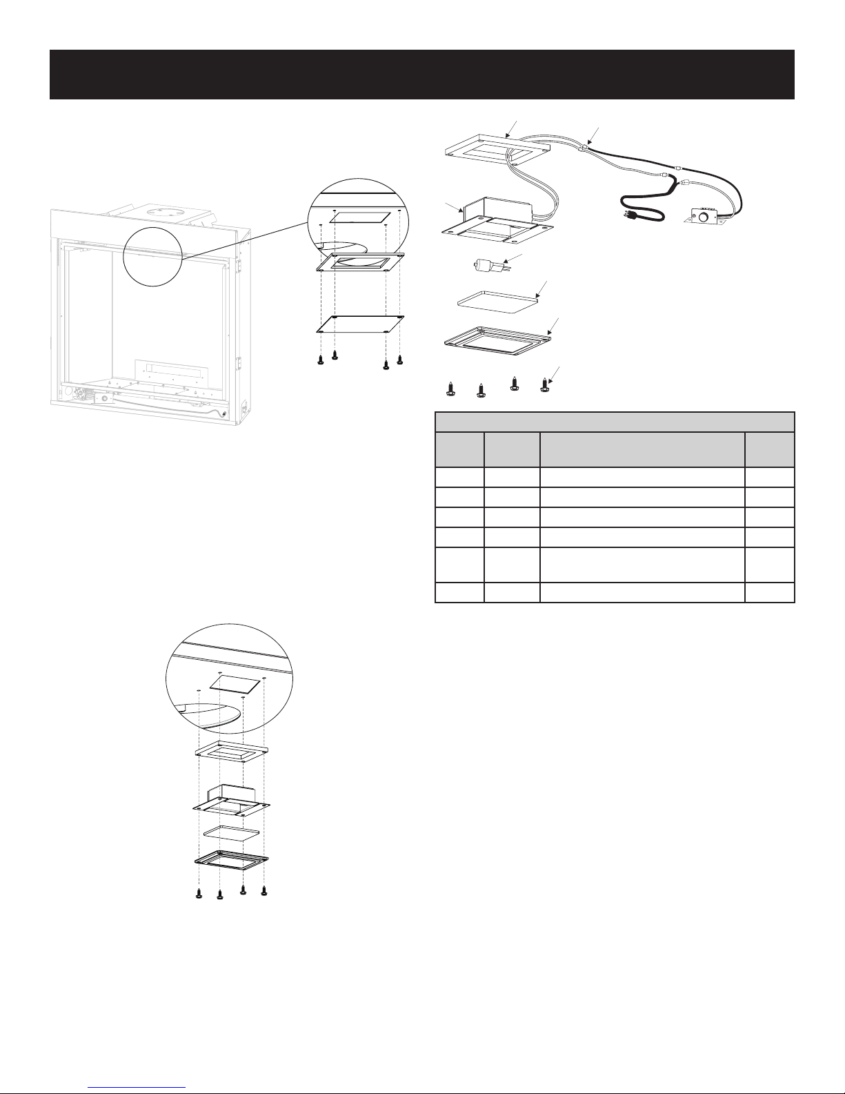
LK6 LIGHT KIT INSTALLATION (OPTIONAL)
1
ALL
1. Remove the four screws securing the metal plate and gasket
to the top of the rebox and discard. See Figure 15.
Figure 15
2. Disconnect the two leads from the light assembly to the control assembly.
3. While wearing gloves, attach the light bulb to the light socket.
4. Feed the light kit wiring through the cut-out and down the right
side of the unit.
5. Secure the bezel, glass, gasket and light assembly to the
rebox with four screws. Note: The painted side of the glass
faces up. See Figure 16.
3
5
4
LIGHT KIT PARTS LIST
INDEX
NO.
PART
NO.
1 32792 ACCENT LIGHT ASSEMBLY 1
2 R9342 BEZEL 1
3 R11751 GASKET 1
4 R11752 GLASS 1
5 R10928
6 R2737 SCREWS-#10 x 1/2 4
DISCONNECT HERE TO INST
LIGHT.
2
6
DESCRIPTION QTY
LIGHT BULB
35W, B1 PIN 6.35mm BASE
1
Figure 16
6. Reconnect the wires disconnected in step two and connect
the power source to the wall outlet.
32261-5-0414Page 12
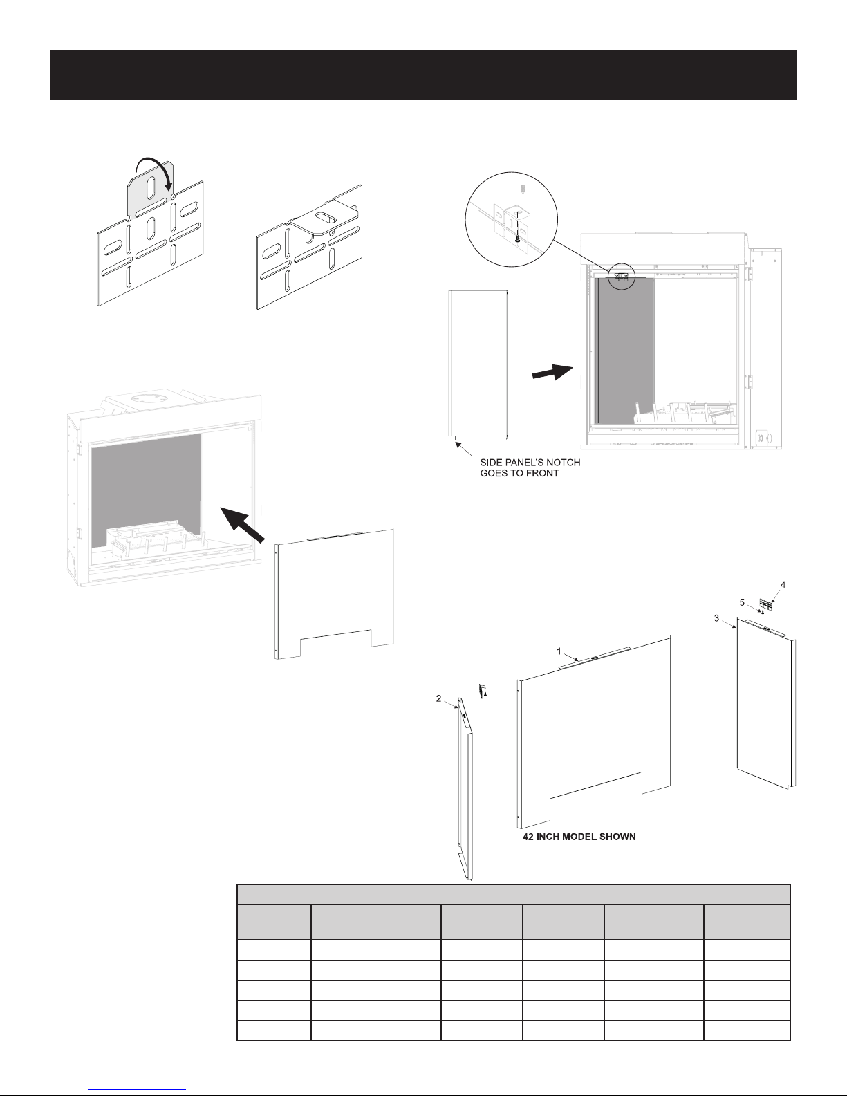
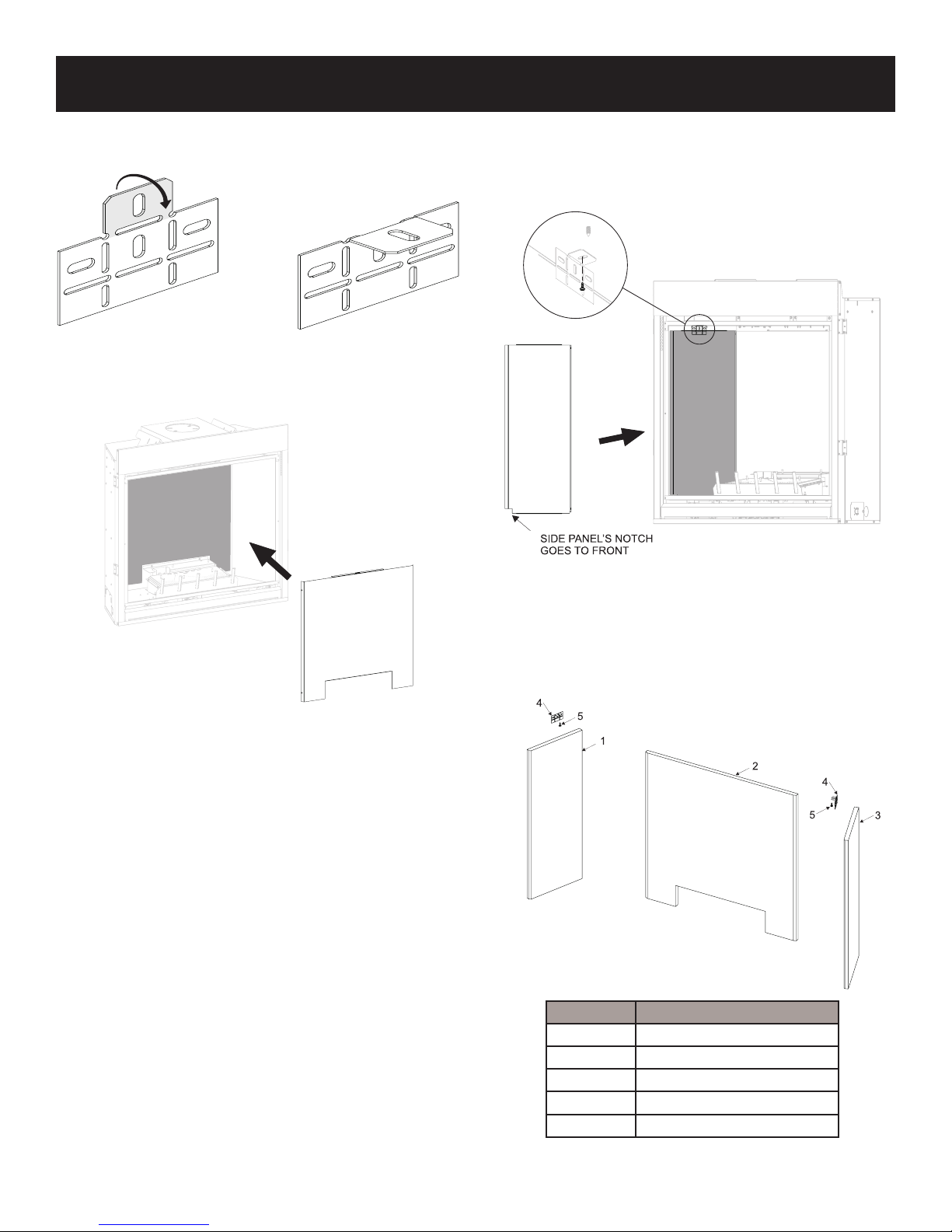
REFLECTIVE LINER KIT INSTALLATION (OPTIONAL)
Installation of Reective Liners
1. Prebend the brackets included with the kit as shown in Figure
17.
Figure 17
2. Place rear panel on log support in the back of the rebox and
hold with one hand. See Figure 18.
3. Place left panel against left rebox and rear panel and hold
side in place.
4. Secure panel in place with one of the brackets and a screw
from Step 1. See Figure 19.
Figure 19
Figure 18
4. Repeat steps three and four for the right side.
REFLECTIVE LINER PARTS LIST
INDEX
NO
1 REAR LINER 1 31927BL 31928BL 31929BL
2 LEFT LINER 1 31930BL 31930BL 31932BL
3 RIGHT LINER 1 31931BL 31931BL 31933BL
4 LINER BRACKET 2 29270 29270 29270
5 SCREWS - #10 x 1/2 2 R2737 R2737 R2737
DESCRIPTION
QTY
SUPPLIED
DVP32TKR DVP36TKR DVP42TKR
32261-5-0414 Page 13
CERAMIC FIBER LINER KIT INSTALLATION (OPTIONAL)
Installation of Ceramic Liners
1. Prebend the brackets included with the kit as shown in Figure
20.
Figure 20
2. Place rear panel on log support in the back of the rebox and
hold with one hand. See Figure 21.
3. Place left panel against left rebox and rear panel and hold
side in place.
4. Secure panel in place with one of the brackets and a screw
from Step 1. See Figure 22.
Figure 22
Figure 21
4. Repeat steps three and four for the right side.
Index No. Description
1 LEFT PANEL
2 REAR PANEL
3 RIGHT PANEL
4 BRACKET
5 SCREW
Contact your Empire Comfort Systems Dealer for ordering information. See Page 49.
32261-5-0414Page 14
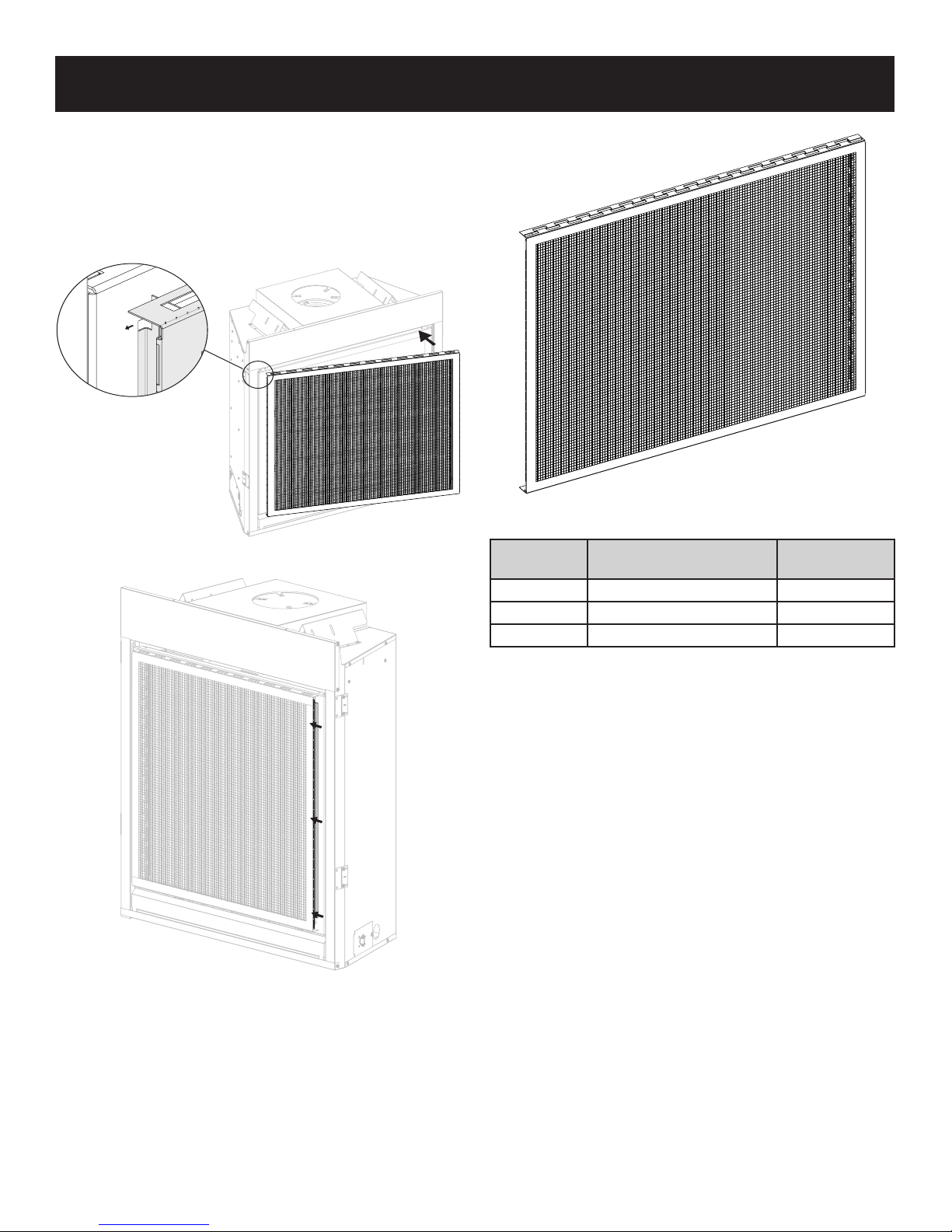
FIREPLACE SCREEN INSTALLATION (OPTIONAL)
Installation of Fireplace Screen
1. Tuck the left side of the replace screen between the glass
frame and glass on the left side of the replace. Push rmly,
bending the replace screen slightly, until you can t the right
side of the replace screen into the space between the glass
frame and glass on the right side of the replace. Carefully
let go, and the replace screen will spring into location. See
Figures 23 and 24.
Figure 23
Figure 24
PART
NUMBER
DVFS32MBL FIREPLACE SCREEN KIT DVCP32
DVFS36MBL FIREPLACE SCREEN KIT DVCP36
DVFS42MBL FIREPLACE SCREEN KIT DVCP42
DESCRIPTION
MODEL
USED ON
32261-5-0414 Page 15
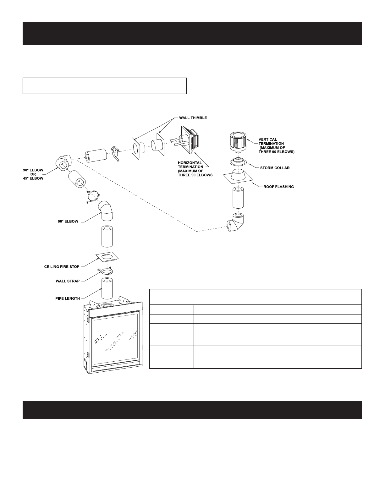
VENT SYSTEM IDENTIFICATION
Begin the vent system installation by selecting the type of venting
to be installed and the path that it will take. Verify that clearances
are met throughout the path of the venting system. Determine if the
replace is to be vented out the top.
NOTE: Unit requires 12 inches of rise before elbow, as well
as 2 inches of clearance around rst 12 inches of pipe.
Figure 25
SPECIAL VENT SYSTEMS
The following vent systems are acceptable for use:
Simpson Duravent® GS 4" - 6 ⅝"
American Metal Products 4” - 6-5/8”
Selkirk Direct-Temp® 4” - 6-5/8”
Security Secure Vent® 4” - 6-5/8”
Empire Flexvent Kit DVVK-4F, refer to page 36 - 37.
Special Venting Components (Simpson Duravent)
See Empire Comfort Systems Retail Price List for Simpson Duravent part numbers
and pricing.
Special DV Vent Kits
Available from Empire Comfort Systems, Inc. dealers
DVVK-4FV Vertical Flex Vent Kit 4" x 7"
DVVK-4VP Direct-Vent Fireplace Vent Kit - Vertical.
Direct-Vent Fireplace Vent Kit for Top Vent, Thru-the-wall, 8 to
DVVK-4TP
DVVK-4TSP
11 inch wall thickness, Includes SD-911, SD-985, SD-990 and
SD-942
Direct-Vent Fireplace Vent Kit for Top Vent, Thru-the-wall, 5 to
7 inch wall thickness, Includes SD-908, SD-985, SD-990 and
SD-942
32261-5-0414Page 16

FIREPLACE DIMENSIONS
Index Letter DVCC32 DVCC36 DVCC42
A 34” (863 mm) 37” (940 mm) 43” (1092 mm)
B 31” (787 mm) 34” (863 mm) 40” (1016 mm)
C 28-7/8” (733 mm) 28-7/8” (733 mm) 30-7/8” (784 mm)
D 38-3/8” (975 mm) 38-3/8” (975 mm) 40-3/8” (1025 mm)
E 38-1/8” (968 mm) 38-1/8” (968 mm) 40-1/8” (1019 mm)
F 16” (406 mm) 16” (406 mm) 16” (406 mm)
H 6-3/4” (171 mm) 6-3/4” (171 mm) 6-3/4” (171 mm)
I 23-1/8” (587 mm) 26-1/8” (663 mm) 32-1/8” (816 mm)
J 11-9/16” (294 mm) 13-1/16” (332 mm) 16-1/16” (408 mm)
K 9-3/16” (233 mm) 9-3/16” (233 mm) 9-3/16” (233 mm)
L 5” (127 mm) 5” (127 mm) 5” (127 mm)
M 2” (51mm) 2” (51mm) 2” (51mm)
N 2” (51 mm) 2” (51mm) 2” (51mm)
O 5-5/16” (135 mm) 5-5/16” (135 mm) 5-5/16” (135 mm)
P 34-3/8” (873mm) 34-3/8” (873mm) 34-3/8” (873mm)
Q 13/16” (21mm) 13/16” (21mm) 13/16” (21mm)
32261-5-0414 Page 17
DIMENSIONS
Figure 26
 Loading...