

Empire Comfort Systems DVC-35SPP, DVC-35IP Installation Instructions And Owner's Manual
INSTALLATION INSTRUCTIONS
AND
OWNER'S MANUAL
FAN TYPE
DIRECT VENT
WALL FURNACE
MODEL
DVC-35-1SPP
DVC-35-1IP
This appliance may be installed in an aftermarket permanently located, manufactured
(mobile) home, where not prohibited by state
or local codes.
This appliance is only for use with the type of
gas indicated on the rating plate. This appliance is not convertible for use with other
gases, unless a certified kit is used.
WARNING: If not installed, operated and
maintained in accordance with the manufacturer's instructions, this product could
expose you to substances in fuel or from fuel
combustion which can cause death or serious illness.
EFFECTIVE DATE
AUGUST, 2000
WARNING: If the information in this
manual is not followed exactly, a fire or
explosion may result causing property
damage, personal injury or loss of life.
— Do not store or use gasoline or other
flammable vapors and liquids in the vicinity of this or any other appliance.
— WHAT TO DO IF YOU SMELL GAS
• Do not try to light any appliance.
• Do not touch any electrical switch; do
not use any phone in your building.
• Immediately call your gas supplier
from a neighbor's phone. Follow the
gas supplier's instructions.
• If you cannot reach your gas supplier ,
call the fire department.
— Installation and service must be per-
formed by a qualified installer, service
agency or the gas supplier.
R-3122 Page 1
Introduction
Always consult your local Building Department regarding
regulations, codes or ordinances which apply to the installation of a direct vent wall furnace.
Instructions to Installer
1. Installer must leave instruction manual with owner after
installation.
2. Installer must have owner fill out and mail warranty card
supplied with furnace.
3. Installer should show owner how to start and operate
furnace and thermostat.
Warning:
Any change to this furnace or its control can be dangerous. This is a heating appliance and any panel, door
or guard removed for servicing an appliance must be
replaced prior to operating the appliance.
Installation on Rugs and Tile
If this appliance is installed directly on carpeting, tile or other
combustible material other than wood flooring the appliance
shall be installed on a metal or wood panel extending the full
width and depth of the appliance.
The base referred to above does not mean the fire-proof base
as used on wood stoves. The protection is for rugs that are
extremely thick and light colored tile.
Installation in Residential Garages
Gas utilization equipment in residential garages shall be installed so that all burners and burner ignition devices are
located not less than 18" (45.7cm) above the floor.
Such equipment shall be located, or protected, so it is not
subject to physical damage by a moving vehicle.
Specifications
General Information
This furnace is design certified in accordance with American
National Standard/CSA Standard Z21.86b-1998 and CSA
2.32b-M98 by the American Gas Association and Canadian
Gas Association, as a fan type direct vent wall furnace to be
installed according to these instructions.
Any alteration of the original design, installed other than
as shown in these instructions or use with a type of gas not
shown on the rating plate is the responsibility of the person
and company making the change.
Important
All correspondence should refer to complete Model No.,
Serial No. and type of gas.
Notice: During initial firing of this unit, its paint will bake out
and smoke will occur. To prevent triggering of smoke alarms,
ventilate the room in which the unit is installed.
THIS IS A HEATING APPLIANCE
DO NOT OPERATE THIS APPLIANCE WITHOUT FRONT PANELS INSTALLED.
• Due to high temperatures the appliance should be lo-
cated out of traffic and away from furniture and draperies.
• Children and adults should be alerted to the hazards of
high surface temperatures and should stay away to avoid
burns or clothing ignition.
• Young children should be carefully supervised when
they are in the same room as the appliance.
• Clothing or other flammable material should not be
placed on or near the appliance.
• Any safety screen or guard removed for servicing an
appliance must be replaced prior to operating the appliance.
• Keep burner and control compartment clean.
• Vent cap hot while furnace is in operation.
• Installation and repair should be done by a QUALIFIED SERVICE PERSON. The appliance should be
inspected before use and at least annually by a
qualified service person. More frequent cleaning
may be required due to excessive lint from carpeting,
bedding materials, etc. It is imperative that control
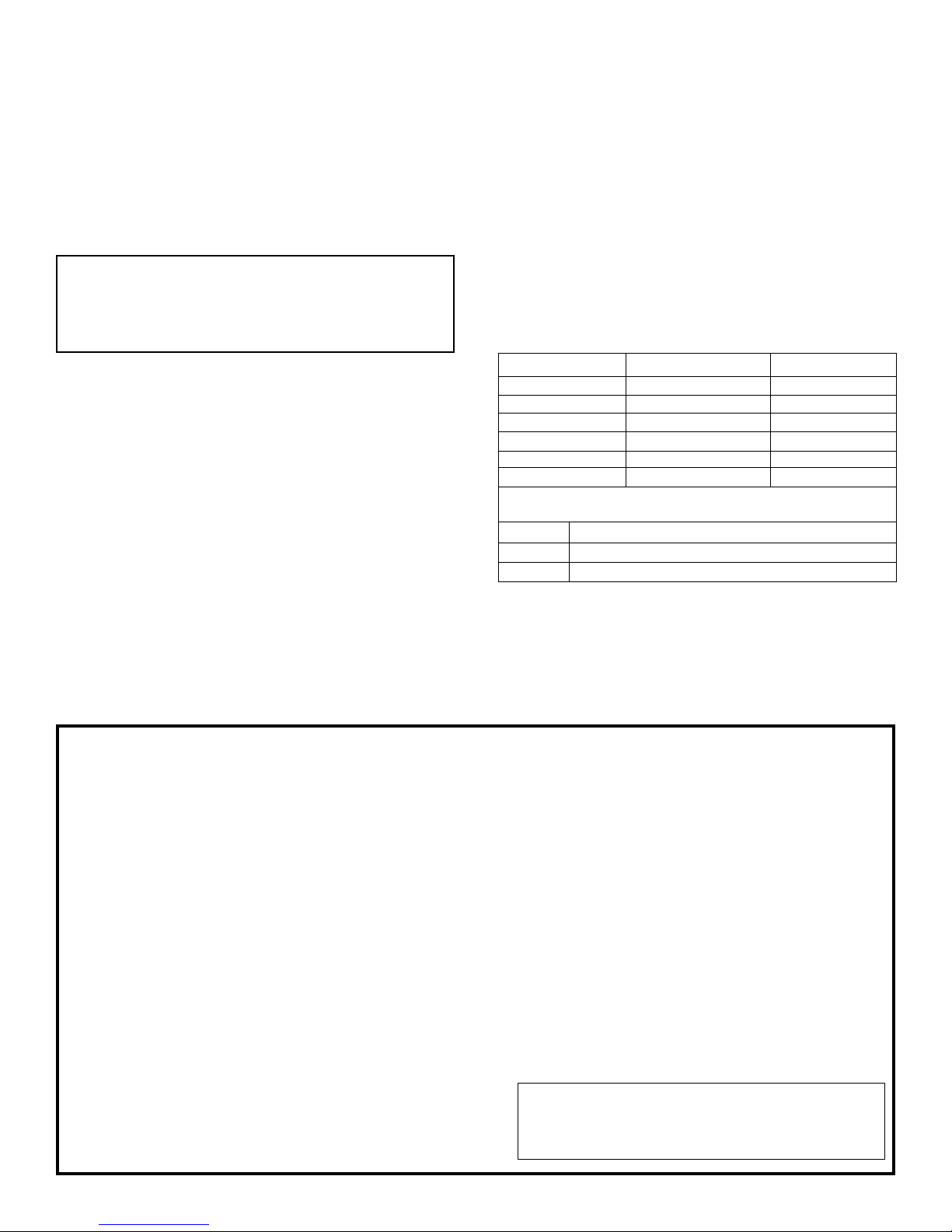
Model DVC-35SPP DVC-35IP
Input BTU/HR 35,000 (10.3) 35,000 (10.3)
Height 72 1/2" (184.2cm) 72 1/2" (184.2cm)
Width 14 1/8" (358mm) 14 1/8" (358mm)
Depth 10 3/8" (264mm) 10 3/8" (264mm)
Gas Inlet 1/2" Pipe (13mm) 1/2" Pipe (13mm)
CFM 275 275
Accessories
SOR-1 Register, Side Outlet
SOK-1 Side Outlet Kit, 10" (25.4cm) Boot Assembly with Register
DV-822 Vinyl Siding Vent Kit
compartments, burners and circulating air passageways
of the appliance be kept clean.
• DO NOT put anything around the furnace that will
obstruct the flow of combustion and ventilation air.
• DO keep the appliance area clear and free from combustible material, gasoline and other flammable vapors and
liquids.
• DO examine venting system periodically and replace
damaged parts.
• DO make a periodic visual check of pilot and burners.
Clean and replace damaged parts.
• CAUTION: Pilot hole cover must be kept tightly closed
during operation.
• DO NOT use this heater if any part has been under water.
Immediately call a qualified service technician to inspect
the heater and to replace any part of the control system
and any gas control which has been under water.
• IMPORTANT: This furnace has a washable perma-
nent type filter which should be cleaned at least once
per year before the heating season. For dirty or high
use areas more frequent cleaning is required.
Page 2 R-3122

SAFETY INFORMATION FOR USERS OF LP-GAS
Propane (LP-Gas) is a flammable gas which can cause fires
and explosions. In its natural state, propane is odorless and
colorless. You may not know all the following safety precautions which can protect both you and your family from an
accident. Read them carefully now, then review them point
LP-GAS WARNING ODOR
If a gas leak happens, you should be able to smell the gas because of the odorant put in the LP-Gas.
That's your signal to go into immediate action!
by point with the members of your household. Someday
when there may not be a minute to lose, everyone's safety will
depend on knowing exactly what to do. If, after reading the
following information, you feel you still need more information, please contact your gas supplier.
• Do not operate electric switches, light matches, use your
phone. Do not do anything that could ignite the gas.
• Get everyone out of the building, vehicle, trailer, or area. Do
that IMMEDIATELY.
• Close all gas tank or cylinder supply valves.
• LP-Gas is heavier than air and may settle in low areas such
as basements. When you have reason to suspect a gas leak,
keep out of basements and other low areas. Stay out until
NO ODOR DETECTED - ODOR FADE
Some people cannot smell well. Some people cannot smell
the odor of the chemical stench put into the gas. You must
find out if you can smell the odorant in propane. Smoking can
decrease your ability to smell. Being around an odor for a time
can affect your sensitivity or ability to detect that odor. Sometimes other odors in the area mask the gas odor. People may not
smell the gas odor or their minds are on something else. Thinking about smelling a gas odor can make it easier to smell.
The odorant in LP-gas is colorless, and it can fade under
some circumstances. For example, if there is an underground
leak, the movement of the gas through soil can filter the odorant.
Odorants in LP-Gas also are subject to oxidation. This fading
firefighters declare them to be safe.
• Use your neighbor's phone and call a trained LP-Gas service
person and the fire department. Even though you may not
continue to smell gas, do not turn on the gas again. Do not
re-enter the building, vehicle, trailer, or area.
• Finally, let the service man and firefighters check for
escaped gas. Have them air out the area before you return.
Properly trained LP-Gas service people should repair the
leak, then check and relight the gas appliance for you.
can occur if there is rust inside the storage tank or in iron gas
pipes.
The odorant in escaped gas can adsorb or absorb onto or into
walls, masonry and other materials and fabrics in a room. That
will take some of the odorant out of the gas, reducing its odor
intensity.
LP-Gas may stratify in a closed area, and the odor intensity could
vary at different levels. Since it is heavier than air, there may be
more odor at lower levels. Always be sensitive to the slightest
gas odor. If you detect any odor, treat it as a serious leak.
Immediately go into action as instructed earlier.
• Learn to recognize the odor of LP-gas. Your local LP-Gas
Dealer can give you a "Scratch and Sniff" pamphlet. Use it
to find out what the propane odor smells like. If you suspect
that your LP-Gas has a weak or abnormal odor, call your LPGas Dealer.
• If you are not qualified, do not light pilot lights, perform
service, or make adjustments to appliances on the LP-Gas
system. If you are qualified, consciously think about the odor
of LP-Gas prior to and while lighting pilot lights or performing service or making adjustments.
• Sometimes a basement or a closed-up house has a musty
smell that can cover up the LP-Gas odor. Do not try to light
pilot lights, perform service, or make adjustments in an area
where the conditions are such that you may not detect the
odor if there has been a leak of LP-Gas.
• Odor fade, due to oxidation by rust or adsorption on walls of
new cylinders and tanks, is possible. Therefore, people
should be particularly alert and careful when new tanks or
cylinders are placed in service. Odor fade can occur in new
tanks, or reinstalled old tanks, if they are filled and allowed
R-3122 Page 3
SOME POINTS TO REMEMBER
to set too long before refilling. Cylinders and tanks which
have been out of service for a time may develop internal rust
which will cause odor fade. If such conditions are suspected
to exist, a periodic sniff test of the gas is advisable. If you
have any question about the gas odor, call your LP-gas
dealer. A periodic sniff test of the LP-gas is a good safety
measure under any condition.
• If, at any time, you do not smell the LP-Gas odorant and you
think you should, assume you have a leak. Then take the
same immediate action recommended above for the occasion
when you do detect the odorized LP-Gas.
• If you experience a complete "gas out," (the container is
under no vapor pressure), turn the tank valve off immediately. If the container valve is left on, the container may draw
in some air through openings such as pilot light orifices. If
this occurs, some new internal rusting could occur. If the
valve is left open, then treat the container as a new tank.
Always be sure your container is under vapor pressure by
turning it off at the container before it goes completely empty
or having it refilled before it is completely empty.
Qualified Installing Agency
Installation and replacement of gas piping, gas utilization equipment or accessories and repair and servicing of equipment shall
be performed only by a qualified agency. The term "qualified
agency" means any individual, firm, corporation or company
which either in person or through a representative is engaged in
and is responsible for (a) the installation or replacement of gas
piping or (b) the connection, installation, repair or servicing of
equipment, who is experienced in such work, familiar with all
precautions required and has complied with all the requirements
of the authority having jurisdiction.
The installation must conform with local codes or, in the
absence of local codes, with the National Fuel Gas Code ANSI
Z223.1*/Canadian Installation Code, CAN/CGA B149.
*Available from the American National Standards Institute, Inc., 11 West 42nd
St., New York, N.Y. 10036.
Clearances
1. In selecting a location for installation, it is necessary to
provide adequate accessibility clearances for servicing and
proper installation. A front clearance of 36" (91.4cm) is
recommended. Do not block outlet or inlet air openings on
the front grill.
2. The DVC-35 minimum wall depth is 3/4" (19mm) and
maximum wall depth is 10" (254mm). The maximum wall
depth may be extended using the model DV-1190 extended
flue kit. The use of tubes not supplied by the manufacturer
results in unsatisfactory performance.
3. The DVC-35 can be attached to the wall or recessed into the
wall up to 9 1/2" (241mm) in depth but the minimum 3/4"
(19mm) vent/air intake system wall depth must be maintained. Example: If furnace is recessed into the wall at a depth
of 9 1/2" (241mm), the minimum wall depth must be 10 1/4"
(260mm).
4. The wall in which the furnace is recessed has (0) zero
clearance to the furnace sides and top.
5. When using side discharge registers, SOR-1 or SOK-1, the
furnace cannot be recessed into the wall.
6. Clearance to sidewall or combustible material is 4" (102mm).
7. Ceiling clearance is 4" (102mm).
8. Floor and rear wall clearance is (0) zero inches.
9. Clearance of 18" (457mm) is required to sidewall or combustible material when flush mounted SOR-1, side outlet register is used.
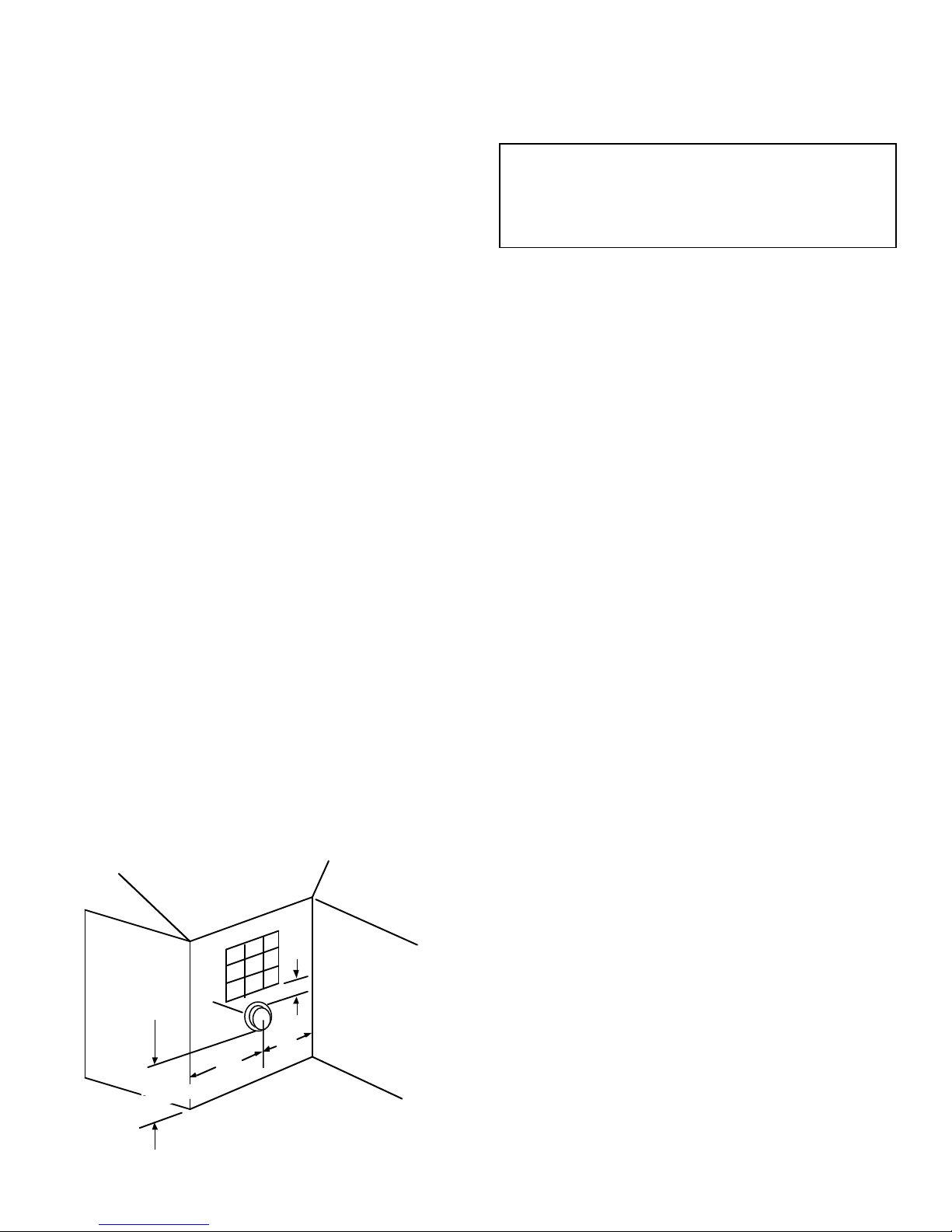
10. The minimum distance from the center of the vent cap to the
nearest outside corner or obstruction is 12" (305mm).
9" min.
12" min.
12" min.
above grade
VENT
12" min.
VENT LOCATION
Maintain spacing of vent away from
landscaping and building overhangs.
Figure 1
The vent terminal of this direct vent appliance shall be located at
least 9" (229mm) from any opening through which flue gases
could enter a building. The bottom of the vent terminal and the air
intake shall be located at least 12" (305mm) above grade. See
vent location, Figure 1.
WARNING: The nearest point of the vent cap should be
a minimum horizontal distant of six (6) feet (1.83m) from
any pressure regulator. In case of regulator malfunction,
the six (6) feet (1.83m) distance will reduce the chance of
gas entering the vent cap.
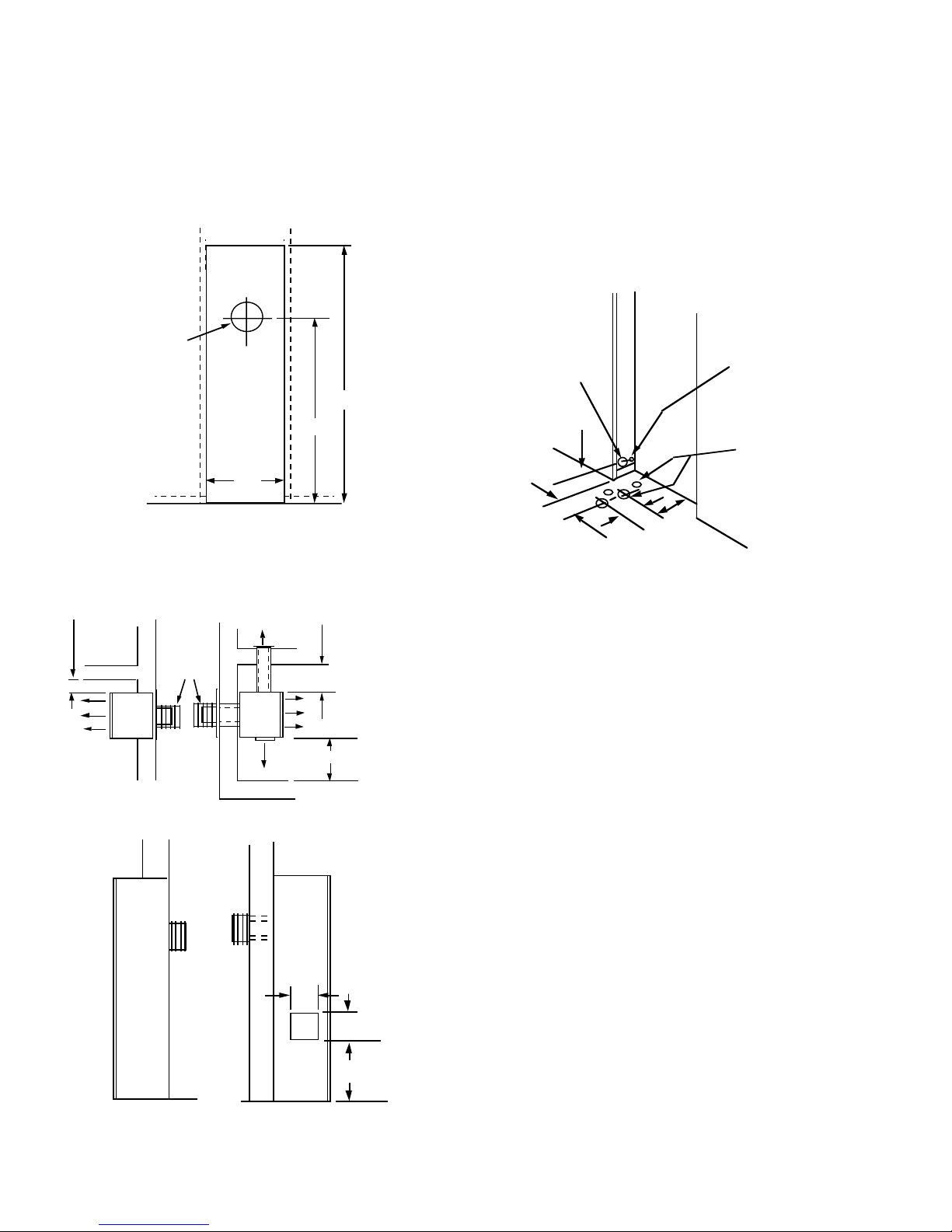
Locating Wall Opening
The furnace is to be located on an outside wall. Locate wall studs
so that wall opening will be located between wall studs. The
furnace is 14 1/8" (358mm) in width and can be recessed between
standard 16" (406mm) on center wall stud. The wall opening
required as shown in Figure 2 is a diameter of 7 1/2" (191mm).
A template is provided in furnace carton for positioning furnace
on the wall. Also, refer to Figure 2 and Figure 4 for positioning
the furnace on wall and for locating gas line connection.
Installing Optional Side Outlets
Side outlet register, SOR-1 may be installed on one or both sides
of the furnace at the required clearances of 18" (457mm) to
adjacent wall or combustible material as shown in Figure 3.
1. Turn "OFF" all electric power to the furnace.
2. Remove the front panel from the furnace.
3. Remove the (2) #8 x 3/8" (9mm) screws that attach the inner
shield cover plate to the inner shield.
4. Scribe a line between the four dimples on the outer casing side
to form a square.
5. Drill a pilot hole within the scribed square on the outer casing.
Remove the sheet metal within the scribed square with a tin
snips or comparable tool. Attention! Do not cut the electrical
wires located between the outer casing and the inner shield.
6. Insert the 5" x 5" (127mm x 127mm) inner boot through the
outer casing. Align the clearance holes on the inner boot with
the screw holes on the inner shield. Attach inner boot to inner
shield with (2) # 8 x 3/8" (9mm) screws removed in Step 3.
7. Place the register over the 5 1/2" (140mm) square opening
with the louvers set for the desired direction and mark the
mounting holes using the register as a template.
8. Drill (2) 1/8" diameter holes in cabinet side and attach the
register with (2) #10 x 1" (25mm) provided screws.
9. Installation of SOR-1 is completed.
Side outlet kit, SOK-1, 10" (254mm) boot assembly with register, for warm air discharge into an adjoining room may be
installed on either side of the furnace at the required clearance of
4" (102mm) to adjacent wall as shown in Figure 3.
To install SOK-1, please use Steps 1 through 5 in the SOR-1
instructions for DVC-35 furnaces. Now, use the following Steps to
complete installation of the SOK-1.
1. Using the inner and outer boots as hole templates, mark and
drill (4) 1/8" (3mm) diameter holes in the inner shield and (4)
1/8" (3mm) diameter holes in the cabinet side.
2. Locate and cut a 6 3/4" (171mm) square opening through wall.
3. Attach furnace to wall (see Attaching Furnace to Wall).
4. With furnace in place, after checking alignment of side outlet
opening in wall and furnace, place the 9 3/8" x 9 3/8" (238mm
x 238mm) side outlet wall plate over outer boot, pass the outer
boot through the wall and attach side wall plate to furnace side
of wall with (2) #10 x 1 1/2" (38mm) provided screws.
5. Attach outer boot to the cabinet side with (4) #8 x 1/4" (6mm)
provided screws.
Page 4 R-3122
4"
4"
ELECTRICAL WIRING HOLE
6. Position and attach inner boot to inner shield with (4) #8 x 1/4"
(6mm) provided screws.
7. Place the register over the 6 3/4" (171mm) square opening
with the louvers positioned for the desired discharge direction
and mark the mounting holes using the register as a template.
8. Drill (2) 1/8" (3mm) diameter holes in the wall and attach the
register with (2) #10 x 1 1/2" (38mm) provided screws.
9. Installation of SOK-1 is completed.
VENT HOLE
7 1/2" DIA.
72 3/4"
59 1/4"
14 3/8"
Locating Gas Supply
The gas line can enter the furnace either through the floor or
outside wall. The gas line opening should be made at this time.
Location of the opening will be determined by the position of floor
joists and the valve and union used for servicing.
Locating Electric Supply
A 7/8" (22mm) diameter knockout is provided at the bottom of the
left and right side panels. A three-prong (grounding) plug assembly is located within the control compartment (bottom) of the
furnace. Please remove 7/8" (22mm) knockout from appropriate
side panel when routing plug assembly to an electrical outlet. Unit
can be hard wired when recessed. Remove the 3 prong plug
assembly and terminate inside the unit junction box.
GAS LINE
HOLE 1 1/4"
2 1/8"
RECESSED MOUNTING
LOCATION
CUT OUT OPENING FOR RECESSED MOUNTING
Figure 2
4" MINIMUM TO COMBUSTIBLE
WALL OR SURFACE
VENT
TERMINAL
CLEARANCE FOR SIDE OUTLET KITS TO ADJACENT WALL
WHEN SIDE REGISTERS ARE
NOT USED UNIT MAY BE RECESSED
UP TO 9 1/2"
Figure 3
4" MINIMUM TO COMBUSTIBLE
WALL OR SURFACE
18" MIN. CLEARANCE TO
WALL OR COMBUSTIBLE
SURFACE USING MODEL
SOR-1 SIDE REGISTER.
UNIT CANNOT BE RECESSED
WHEN SIDE REGISTERS ARE
USED.
5 1/2"
5 1/2"
12"
8"
GAS LINE/ELECTRICAL OPENINGS FOR
RECESSED AND SURFACE MOUNT
Figure 4
Installation of Three-prong (Grounding) Plug Assembly
1. Disconnect nylon cap on 3' (92cm) plug assembly from nylon
plug on wiring harness. Remove 3' (92cm) plug assembly from
control compartment (bottom) of the furnace.
2. Remove 7/8" (22mm) knockout from appropriate side panel.
3. Insert nylon cap on 3' plug assembly into the 7/8" (22mm) hole
in the side panel.
4. Connect nylon cap on 3' (92cm) plug assembly to nylon plug on
the wiring harness.
5. Place 7/8" (22mm) strain relief bushing around the cord of the
3' (92cm) plug assembly. Insert 7/8" (22mm) strain relief
bushing into the 7/8" (22mm) hole in the side panel.
Attention! The 7/8" (22mm) strain relief bushing is located within
the same yellow envelope as the Installation Instructions and
Owner's Manual.
Attaching Furnace to Wall
Refer to Figure 2 for the location of the 7 1/2" (191mm) diameter
wall opening for the furnace. After the wall opening has been
located and cut, position flue outlet on furnace in center of wall
opening. When attaching furnace to the wall remove that portion
of baseboard and molding on the wall which is behind the furnace.
Attach furnace to wall, at the outer casing top, with (2) toggle bolts
provided and to floor, at the outer casing bottom, with (2) #10 x 1
1/2" (38mm) screws provided.
Cutting Vent Tubes
This is the most important part of the installation. With the furnace
installed on wall the 6" (152mm) diameter air inlet tube and the 4"
(102mm) diameter flue outlet tube are to be marked and cut using
the following procedure.
1. Attach 6" (152mm) diameter air inlet tube onto the collar of air
drop assembly. Be sure 6" (152mm) diameter air inlet tube is
placed as far as possible onto the collar of the air drop assembly.
R-3122 Page 5
 Loading...