

Empire Comfort Systems DVC20IN71-1, DVC26IN31-1, DVC20IN31P-1, DVC20IN31N-1, DVC20IN71P-1 Installation Instructions And Owner's Manual
...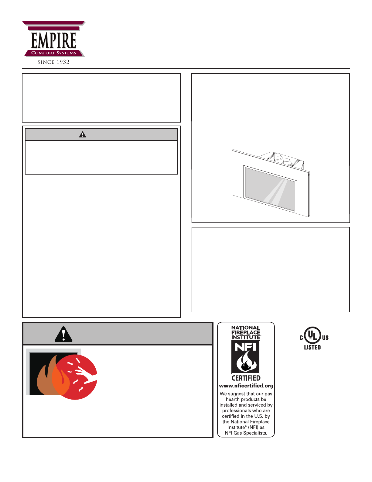
GAS-FIRED
INSTALLATION INSTRUCTIONS
AND OWNER’S MANUAL
INSTALLER:
Leave this manual with the appliance.
CONSUMER:
Retain this manual for future reference.
WARNING
FIRE OR EXPLOSION HAZARD
Failure to follow safety warnings exactly
could result in serious injury, death or
property damage.
— Do not store or use gasoline or other
ammable vapors and liquids in the
vicinity of this or any other appliance.
— WHAT TO DO IF YOU SMELL GAS
• Do not try to light any appliance.
• Do not touch any electrical switch; do
not use any phone in your building.
• Leave the building immediately.
• Immediately call your gas supplier
from a neighbor’s phone. Follow the
gas supplier’s instructions.
• If you cannot reach your gas supplier,
call the re department.
— Installation and service must be
performed by a qualied installer,
service agency or the gas supplier.
DIRECT VENT
GAS FIREPLACE HEATER
FIREPLACE
INSERT MODELS
DVC(20,26,28)IN31(N,P)-1
DVC(20,26,28)IN71(N,P)-1
This appliance may be installed into a listed
wood-burning replace in an aftermarket,
permanently located, manufactured home
(USA only) or mobile home, where not
prohibited by state or local codes.
This appliance is only for use with the type
of gas indicated on the rating plate. This
appliance is not convertible for use with
other gases, unless a certied kit is used.
DANGER
HOT GLASS
CAUSE BURNS.
DO NOT TOUCH
UNTIL COOLED.
NEVER
A barrier designed to reduce the risk of burns from the
hot viewing glass is provided with this appliance and shall
be installed for the protection of children and other at-risk
individuals.
ALLOW CHILDREN
TO TOUCH GLASS.
WILL
GLASS
UL FILE NO. MH30033
This replace is design
certied in accordance
with American National
Standard/CSA Standard
ANSI Z21.88/CSA 2.33
and by Underwriters
Laboratories as a Direct
Vent Gas Fireplace
Heater and shall be
installed according to
these instructions.
Page 1

TABLE OF CONTENTS
SECTION PAGE
Before You Start ......................................................................................................................................... 3
Carton Contents & Hardware Pack ............................................................................................................ 4
Specications ............................................................................................................................................. 5
Homeowner Reference Information ............................................................................................................ 5
Accessories ................................................................................................................................................ 6
Introduction ................................................................................................................................................. 8
Fireplace Insert Dimensions ..................................................................................................................... 10
Minimum Fireplace Opening Dimensions ..................................................................................................11
Mantel and Trim Clearances ......................................................................................................................11
Gas Supply ............................................................................................................................................... 12
Fireplace Preparation ............................................................................................................................... 14
Venting ...................................................................................................................................................... 15
Installation ................................................................................................................................................ 16
Installation Diagram .................................................................................................................................. 17
Vertical Termination .................................................................................................................................. 18
Surround Installation ................................................................................................................................. 19
Alternate ON/OFF Switch Installation ....................................................................................................... 20
Barrier Screen Installation ........................................................................................................................ 22
Blower Information .................................................................................................................................... 23
Log Identication ...................................................................................................................................... 24
Log Placement .......................................................................................................................................... 25
Placement of Glowing Embers and Optional Lava Rock .......................................................................... 32
Operating Instructions .............................................................................................................................. 33
Standing Pilot Lighting Instructions .......................................................................................................... 34
Standing Pilot Wiring ................................................................................................................................ 35
Standing Pilot Troubleshooting ................................................................................................................. 36
IPI System Operating Instructions ............................................................................................................ 37
IPI System Electronic System Wiring Diagram ......................................................................................... 38
Intermittent Pilot Lighting Instructions ....................................................................................................... 39
Intermittent Control System Troubleshooting ........................................................................................... 40
Maintenance and Service ......................................................................................................................... 43
Insert Parts View ...................................................................................................................................... 45
Insert Parts List ......................................................................................................................................... 46
Master Parts Distributor List ..................................................................................................................... 48
How To Order Repair Parts ...................................................................................................................... 48
Important Safety Information .................................................................................................................... 49
Safety Information for Users of LP-Gas .................................................................................................... 50
For the Homeowner ................................................................................................................... 51 - 61
Important Information ............................................................................................................................... 52
Standing Pilot (DVC(20,26,28)IN3 Models) Operating Instructions .......................................................... 55
Standing Pilot (DVC(20,26,28)IN3 Models) Lighting Instructions ............................................................. 56
Intermittent Pilot (DVC(20,26,28)IN7 Models) Operating Instructions ...................................................... 57
Intermittent Pilot (DVC(20,26,28)IN7 Models) Lighting Instructions ......................................................... 58
Important Safety Information .................................................................................................................... 59
Appliance Service History ......................................................................................................................... 60
Warranty ................................................................................................................................................... 61
36561-5-0817Page 2
BEFORE YOU START
WARNING
Read and follow these safety precautions prior to operating this appliance. Failure to follow these precautions may
result in death, injury, or property damage.
Samples and Denitions:
DANGER
Indicates a hazardous situation which, if not avoided, will
result in death or serious injury.
WARNING
Indicates a hazardous situation which, if not avoided, could
result in death or serious injury.
CAUTION
Indicates a hazardous situation which, if not avoided, could
result in minor or moderate injury.
NOTICE: Addresses practices not related to personal injury.
Attention! If the replace insert is installed into a modied
wood-burning, factory-built replace, the replace cannot
be returned to a wood-burning replace. See page 14 for
additional details regarding the allowed modications to a
factory-built replace.
Read all instructions before starting installation and follow them
carefully to insure safety. Failure to follow the instructions will
void the warranty and may cause a re hazard.
The warranty will be voided by, and the warranter disclaims any
responsibility for the following actions:
• Installation of any damaged replace insert or vent system
component.
• Modication of the replace insert or direct vent system.
• Installation other than as instructed by Empire Comfort
Systems Inc.
• Improper positioning of logs, glass door, barrier screen, or
decorative accessories.
• Installation and/or use of any component part not
manufactured or approved by the manufacturer.
Preparation
This replace insert and its components are safe when installed
in accordance with this Installation Manual. Report any parts
damaged in shipment to your dealer. Do not install the replace
insert with damaged, incomplete or substitute parts.
Installation Considerations
• The rebox must be in good working order and sized
according to page 11.
• Gas supply piping – right or left side entrance
• Electrical supply and connections – for blower
• 120V, 60Hz, 1 Amp
• Right side entrance
• Surround Requirements - See Fireplace Insert Dimensions,
page 10 and Accessories, page 6.
• Surround Bottom Cover - For elevated insert installations.
See Accessories, page 6.
• Shroud Requirements - See Accessories, page 6.
• Leveling the Insert - Four leveling bolts are included in
the Hardware Pack. See page 4 for size and page 16 for
installation and use.
1. Read the safety information pages 49 - 50 and 59.
2. Place the sticker located in the instruction envelope onto the
“Homeowner Reference Information” page 5.
3. Show the homeowner where the rating plate and lighting
instruction plate are located.
6. Install and connect the gas lines. See pages 12 and 13.
7. Install the wiring. See pages 35 and 38.
8. Install the venting. See pages 15 - 17.
9. Install the replace insert. See page 16.
10. Light the replace insert. See pages 34 and 39.
11. Troubleshoot issues. See pages 36, and 40 - 42.
12. Show the homeowner how to operate the replace insert.
13. Show the homeowner how do the basic maintenance.
All correspondence should refer to complete Model Number,
Serial Number and type of gas. Fill out the Homeowner
Reference Section on page 5.
Unpacking the replace insert
1. Cut binding straps.
2. Remove the top carton.
3. Carefully remove the carton contents.
4. Use the Carton Contents and Hardware Pack lists on page 4
to verify all components are present.
5. Verify that the replace insert and components have not
been damaged during shipping.
6. Set replace insert in a location near its nal installation
location.
36561-5-0817 Page 3
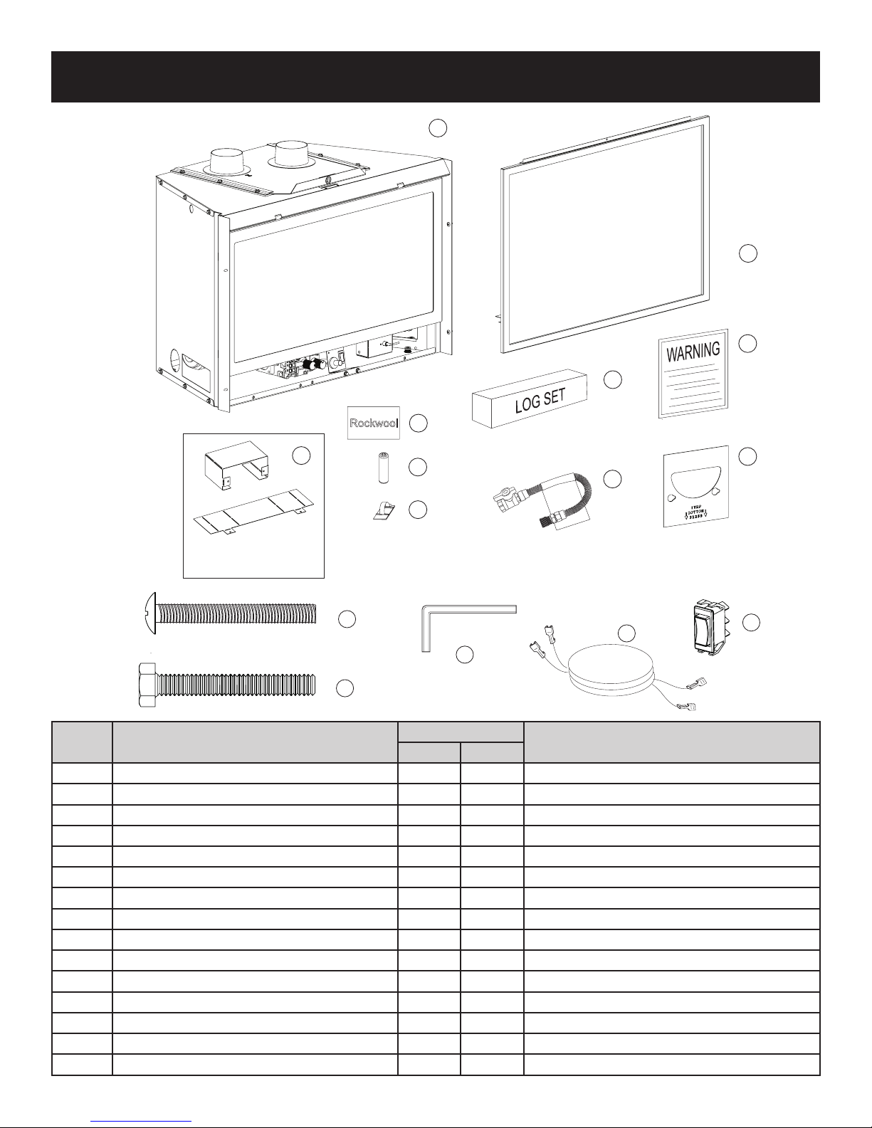
CARTON CONTENTS & HARDWARE PACK
12
13
14
11
1
5
2
3
NOTE: Ships as flat part
REQUIRED when using
a remote receiver
Index
Number
Description
1 Fireplace Insert 1 1 In carton
2 Barrier Screen Assembly 1 1 Front of Insert
3 Warning Label Plate 1 1 In envelope
4 Restrictor Plate 1 1 In envelope
5 Log Set 1 1 Inside Insert rebox
6 Flex Line with Shutoff 1 1 Attached to the gas valve
7 Rockwool Embers 1 1 In envelope
8 AA Batteries 0 4 In envelope
9 Wire Retainer Clips 3 3 In envelope
10 ON/OFF Switch 1 1 In envelope
11 Extension Wire Harness 1 1 In envelope
12 3/16 Allen Wrench 1 1 In envelope
13 5/16-18 Allen Head bolt, 2-1/2 inches long 1 1 In envelope
14 5/16-18 Hex Head bolt, 2-1/2 inches long 4 4 In envelope
15 Shield, Remote Receiver 1 1 In envelope
15
Rockwool
7
8
9
Quantity Supplied
MV IP
4
6
10
Location
36561-5-0817Page 4

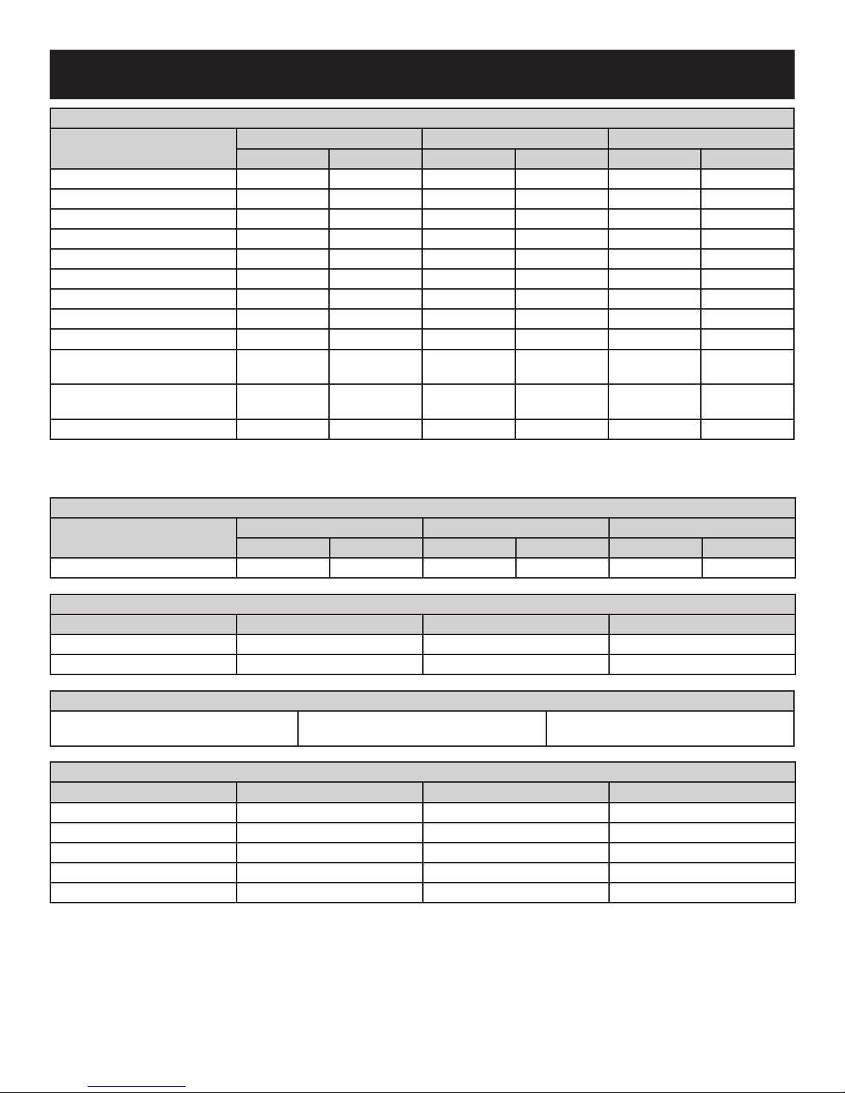
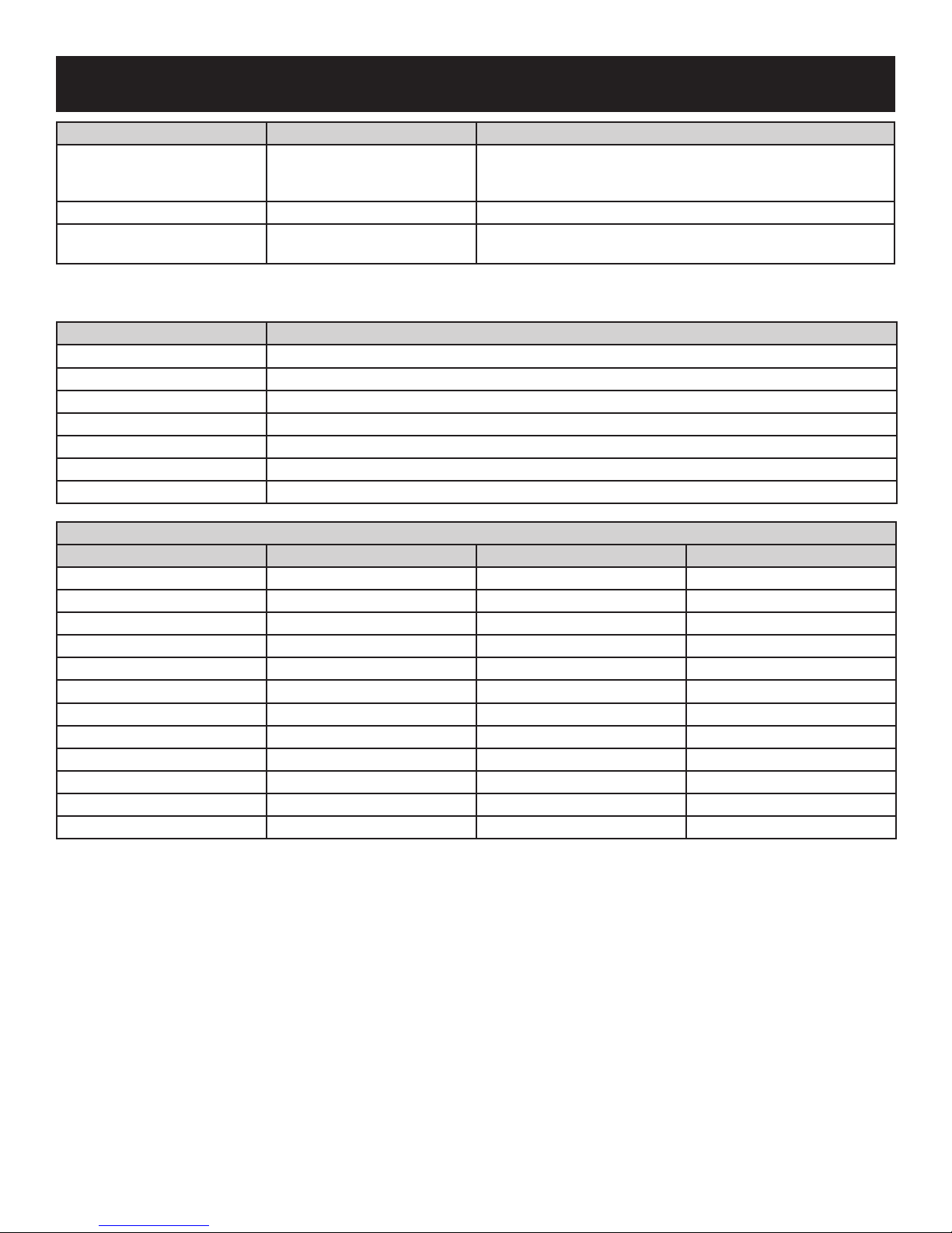
SPECIFICATIONS
DVC20IN(3,7) DVC26IN(3,7) DVC28IN(3,7)
LP N AT LP N AT LP N AT
Input BTU/Hr Maximum 19,500 20,500 26,000 26,000 27,500 28,500
Input BTU/Hr Minimum 15,000 14,500 20,000 17,000 21,000 18,500
KWH (Maximum) 5.37 5.95 7.54 7.54 7.98 8.27
KWH (Minimum) 4.2 4.2 5.8 5.36 6.38 5.36
Orice 1.30mm #44 #53 #40 1.55mm 2.60mm
Air Shutter Opening 1/2 inch open 1/8 inch open 1/2 inch open 3/16 inch open 1/2 inch open 3/16 inch open
Gas Inlet Shutoff Valve (pipe) 1/2 NPT 1/2 NPT 1/2 NPT 1/2 NPT 1/2 NPT 1/2 NPT
NOTICE: Air shutter settings are factory minimum settings. Some venting congurations may require minor air shutter adjustments for
optimum performance.
GAS SUPPLY PRESSURES
GAS TYPE MAXIMUM MINIMUM MANIFOLD
NAT 14 4.5 3.5
LP 14 11 10
HOMEOWNER REFERENCE INFORMATION
We recommend that you record the following information about your replace.
Model Number: _____________________________ Date purchased: ________________________
Serial Number: _____________________________ Location of replace: _____________________
Dealer Name: ______________________________ Dealer Phone: _________________________
Notes: ______________________________________________________________________________
36561-5-0817 Page 5
ACCESSORIES
SURROUNDS (REQUIRED)
DVC20IN DVC26IN DVC28IN
Black Bronze Black Bronze Black Bronze
3 x 6 x 1 DS2063BL DS2063BZ DS2663BL DS2663BZ DS2863BL DS2863BZ
3 x 6 x 1 Bottom Cover C203BL C203BZ C263BL C263BZ C283BL C283BZ
3 x 6 x 2-1/4* DS2063DBL DS2063DBZ - - - -
3 x 6 x 2-1/4 Bottom Cover C203DBL C203DBZ - - - -
6 x 6 x 1 DS2066BL DS2066BZ DS2666BL DS2666BZ DS2866BL DS2866BZ
9 x 6 x 1 DS2096BL DS2096 BZ DS2696BL DS2696BZ DS2896BL DS2896BZ
6 x 6 x 1 Bottom Cover C206BL C206BZ C266BL C266BZ C286BL C286BZ
6 x 6 x 2-1/4* DS2066DBL DS2066DBZ - - - -
9 x 6 x 2-1/4 DS2066DBL DS2066DBZ - - - -
6 x 6 x 2-1/4 or 6 x 9 x 2-1/4
Bottom Cover
6-Inch Cast Iron (Requires
Adator Kit)
Cast Iron Surround Adaptor Kit SAK20 - SAK26 - SAK28
*NOTICE: DVC20IN replace inserts can be installed with either surround. The 6 x 6 x 2-1/4 or 9 x 6 x 2-1/4 inch surround allows the
replace insert to be installed in a 13-5/8 inch deep replace. This option is not available for DVC(26,28)IN replace insert models.
C206DBL C206DBZ - - - -
SC256BL - SC336BL - SC356BL -
-
DECORATIVE FRONT (REQUIRES SURROUND)
DVC20IN DVC26IN DVC28IN
Black Bronze Black Bronze Black Bronze
Lancaster DVF20HBL DVF20HBZ DVF26HBL DVF26HBZ DVF28HBL DVF28HBZ
DOOR FRONTS (REQUIRES SURROUND)
DVC20IN DVC26IN DVC28IN
Transom DFD20DBL DFD26DBL DFD28DBL
Horizon DFD20HBL DFD26DHBL DFD28HBL
SHROUD (REQUIRES SURROUND)
SH1BL Black
LINERS
DVC20IN DVC26IN DVC28IN
Porcelain Black DVP20KR DVP26KR DVP28KR
Banded Brick* DVP20AE DVP26AE DVP28AE
Traditional Aged Brick DVP20DF DVP26DF DVP28DF
Traditional Washed DVP20BW DVP26BW DVP28BW
Herringbone* DVP20SH DVP26SH DVP28SH
* Herringbone Liners available only for American Hearth models; Banded Brick Liners available only for White Mountain Hearth models.
For replace openings up to (in inches)
48H x 36W
36561-5-0817Page 6
ACCESSORIES
Venting Kits Description Contents
High Wind Round Cap, Flashing, connectors, and clamps.
DVKI2P Vertical Vent Kit 17-1/2’
DVK35 Vent Extension Kit
SD46DVACL33 High Wind Vertical Vent Kit
NOTICE: When installing vent caps, special locally made ashings may be required to properly seal the vent system to the existing
chimney termination.
Remote Controls Description
FRBC Millivolt Battery Remote ON/OFF
FRBTC Millivolt Battery Remote Thermostat
TRW Millivolt Wireless Wall Thermostat
TMV Millivolt Reed Switch Wall Thermostat
FWS-1 Millivolt Wall Switch
RVKN Remote Control Variable Flame Height Kit (Nat) (DVC(20,26,28)IN71N only)
RVKP Remote Control Variable Flame Height Kit (LP) (DVC(20,26,28)IN71P only)
GAS CONVERSION KITS
Kit Number Conversion Type Used On Valve Type
36395 LP to NAT DVC20IN3 MV
36396 NAT to LP DVC20IN3 MV
36722 LP to NAT DVC20IN7 IP
36723 NAT to LP DVC20IN7 IP
36397 LP to NAT DVC26IN3 MV
36398 NAT to LP DVC26IN3 MV
36724 LP to NAT DVC26IN7 IP
36725 NAT to LP DVC26IN7 IP
36399 LP to NAT DVC28IN3 MV
36400 NAT to LP DVC28IN3 MV
36726 LP to NAT DVC28IN7 IP
36727 NAT to LP DVC28IN7 IP
Recommended when installing to an existing round replace
chimney pipe.
35 foot ex vent extension section with 2 connectors and 4 clamps
Two 3-inch diameter X 35-feet long lengths of Flex venting, High
Wind Round Termination, ashing, and clamp connectors
36561-5-0817 Page 7
INTRODUCTION
Instructions to Installer
1. Leave this manual with the homeowner.
2. Have the homeowner ll out and mail the Product
Registration Card supplied with the replace insert or online
at www.empirecomfort.com.
3.
Show the homeowner how to start and operate the
replace insert.
4. Manually attach the warning label plate supplied with the gas
replace insert to the inside of the rebox of the replace into
which the gas replace insert is installed.
5. Run replace insert for a minimum 30 to 35 minutes to
burn off oils from manufacturing. Failure to perform this
initial burn-off can cause pilot problems. After burn-off,
clean ame sensor on IP pilot assembly. See page 39 for
sensor location.
Important
All correspondence should refer to complete Model Number,
Serial Number and type of gas.
Qualied Installing Agency
Installation and replacement of gas piping, gas utilization
equipment or accessories and repair and servicing of equipment
shall be performed only by a qualied agency. The term “qualied
agency” means any individual, rm, corporation or company
which either in person or through a representative is engaged
in and is responsible for (a) the installation or replacement of
gas piping or (b) the connection, installation, repair or servicing
of equipment, who is experienced in such work, familiar with all
precautions required and has complied with all the requirements
of the authority having jurisdiction.
Commonwealth of Massachusetts: The installation must be
made by a licensed plumber or gas tter in the Commonwealth
of Massachusetts.
Installation and repair should be done by a qualied service
person. The appliance should be inspected before use and at least
annually by a qualied service person. More frequent cleaning
may be required due to excessive lint from carpeting, bedding
material, etc. It is imperative that control compartments, burners
and circulating air passageways of the appliance be kept clean.
High Altitude
When installing this unit at an elevation above 2000 feet (in
the United States) it may be necessary to decrease the input
rating by changing the existing burner orice to a smaller size.
Generally, input should be reduced 4 percent for each 1000 feet
above sea level. However, if the heating value of the gas has
been reduced, this general rule may not apply. Conrm orice
size with Empire Comfort Systems.
Canadian High Altitude
Altitude: 0-4500 feet (0-1370 m)
When installing this unit at an elevation above 4500 feet (in
Canada), check with local authorities.
Consult your local gas utility for assistance in determining the
proper orice for location.
Well Head Gas Installations
Some natural gas utilities use “well head” gas. This may affect
the Btu output of the unit and promote sooting. Units shall not be
converted to use well head gas.
Building Codes
Consult your local building code agency, prior to installation,
to ensure compliance with local codes-including permits and
inspections.
• The installation must conform with local codes or, in the
absence of local codes, with the National Fuel Gas Code
ANSI Z223.1/NFPA 54* Natural Gas and Propane Installation
Code, or CSA B149.1 in Canada. *Available from the
American National Standards Institute, Inc. 11 West 42nd
St., New York, N.Y. 10036.
• The replace insert, when installed, must be electrically
grounded in accordance with local codes or, in absence of
local codes, with the National Electric Code ANSI/NFPA
70 or Canadian Electric code, CSA C22.1, if an external
electrical source is utilized.
Preparation
This direct vent gas replace insert and its components
are tested and safe when installed in accordance with this
Installation Manual. The replace insert must be installed into
a wood-burning replace. Report to your dealer any parts
damaged in shipment, specically check glass condition. Do
not install unit with damaged, incomplete, or substitute parts.
Read all instructions before starting installation and follow these
instructions carefully during installation to ensure maximum
benet and safety. Failure to follow them will void the warranty
and may present a re hazard.
This direct vent gas replace insert is designed to operate with
combustion air siphoned from and all exhaust gases expelled
to the outside of the building. The information contained in this
manual pertains to all models and gas control systems listed on
the front page unless otherwise noted.
These models may be installed in a bedroom or bed-sitting room
in the U.S.A. and Canada.
WARNING
Any change to this replace insert or its controls can be
dangerous. Improper installation or use of the replace
insert can cause serious injury or death from re, burns,
explosions, or carbon monoxide poisoning.
Before enclosing the vent pipe assembly, operate the
appliance to ensure it is venting properly.
Do not operate this appliance without the glass door installed.
• Due to high temperatures, the appliance should be located
out of trafc and away from furniture and draperies.
• Only trim kit(s) supplied by the manufacturer shall be used in
the installation of this appliance.
• Any safety screen, guard, or barrier removed to service an
appliance must be replaced prior to operating the appliance.
• If the barrier becomes damaged, the barrier shall be
replaced with the manufacturer’s barrier for this appliance.
• A barrier designed to reduce the risk of burns from the
hot viewing glass is provided with this appliance and shall
be installed for the protection of children and other at-risk
individuals.
• Only doors certied with the appliance shall be used.
• The glass front or any part removed for servicing the
appliance must be replaced prior to operating the appliance.
36561-5-0817Page 8

INTRODUCTION
Warranty Information
Any alteration of the original design, installed other than as
shown in these instructions or use with a type of gas not shown
on the rating plate is the responsibility of the person and
company making the change.
The warranty will be voided by, and the warranter disclaims any
responsibility for the following actions:
• Installation of any damaged replace insert or vent system
component.
• Modication of the replace insert or direct vent system.
• Installation other than as instructed by Empire Comfort
Systems, Inc.
• Improper positioning of the logs or glass door assembly.
• Installation and/or use of any component part not
manufactured or approved by manufacturer.
• This appliance comes standard with a 120 V/AC cord
assembly to accommodate the blower accessory. An outlet
box may be installed in a bottom back corner of the existing
solid fuel masonry or factory built replace to plug in the cord
assembly, or the supplied power cord may be routed out
onto the hearth to a nearby outlet.
• A 120 V/AC circuit for this product must be protected with
ground-fault circuit-interrupter protection, in compliance
with the applicable electrical codes, when it is installed in
locations such as in bathrooms or near sinks.
• Low voltage and 120 V/AC cannot be shared within the
same wall box.
• Once the appliance installation is completed, the installer
should check that control compartment wiring is secured in
a manner as to not interfere with blower, door latches, valve
controls, or the barrier assembly.
36561-5-0817 Page 9
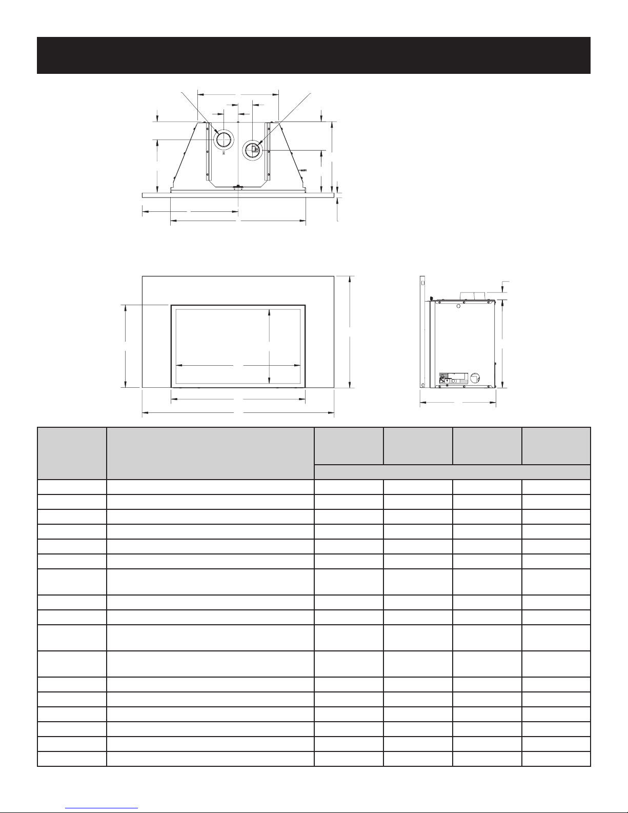
FIREPLACE INSERT DIMENSIONS
INTAKE
3” Dia.
3
4
3/”
K
I
D
G
3”
3”
L
M
N
FLUE
3” Dia.
6”
J
F
O
1
1/”
2
A
H
E
B
DVC20IN
INDEX
LETTER
A Surround Height 23-1/4 23-1/4 26-1/4 28-1/4
DIMENSION DESCRIPTION
with 1-inch
Surround
DVC20IN
with Deep
Surround
Dimensions in Inches
C
DVC26IN DVC28IN
B Surround width with 3-inch wide Surround Legs 34 34 37 40
B Surround width with 6-inch wide Surround Legs 40 40 43 46
C Overall Depth of Insert including Surround 15-7/8 15-7/8 17-5/8 17-5/8
D Barrier Screen Height 17-1/4 17-1/4 20-1/4 22-1/4
E Barrier Screen Width 27-7/8 27-7/8 30-7/8 33-7/8
F
Insert depth - from back of Surround to rear of
insert
14-7/8 13-5/8 16-5/8 16-5/8
G Rear width of Insert 17 17 18-3/4 21-3/4
H Height of Insert 18-1/2 18-1/2 21-1/2 23-1/2
I
I
Centerline of Insert to outside of 3-inch wide
Surround Leg
Centerline of Insert to outside of 6-inch wide
Surround Leg
17 17 18-1/2 20
20 20 21-1/2 23
J Back of Surround to Centerline of Flue Outlet 8-7/8 7-5/8 10-9/16 10-9/16
K Back of Surround to Centerline of Air Inlet 11-3/16 9-15/16 12-7/8 12-7/8
L Front width of Insert cabinet 28-3/16 28-3/16 31-3/16 34-3/16
M Barrier Screen opening height 15-1/2 15-1/2 18-1/2 20-1/2
N Barrier Screen opening width 25-15/16 25-15/16 28-15/16 31-15/16
O Surround depth 1 2-1/4 1 1
36561-5-0817Page 10
8” MIN. DIA. FLUE
REQUIRED
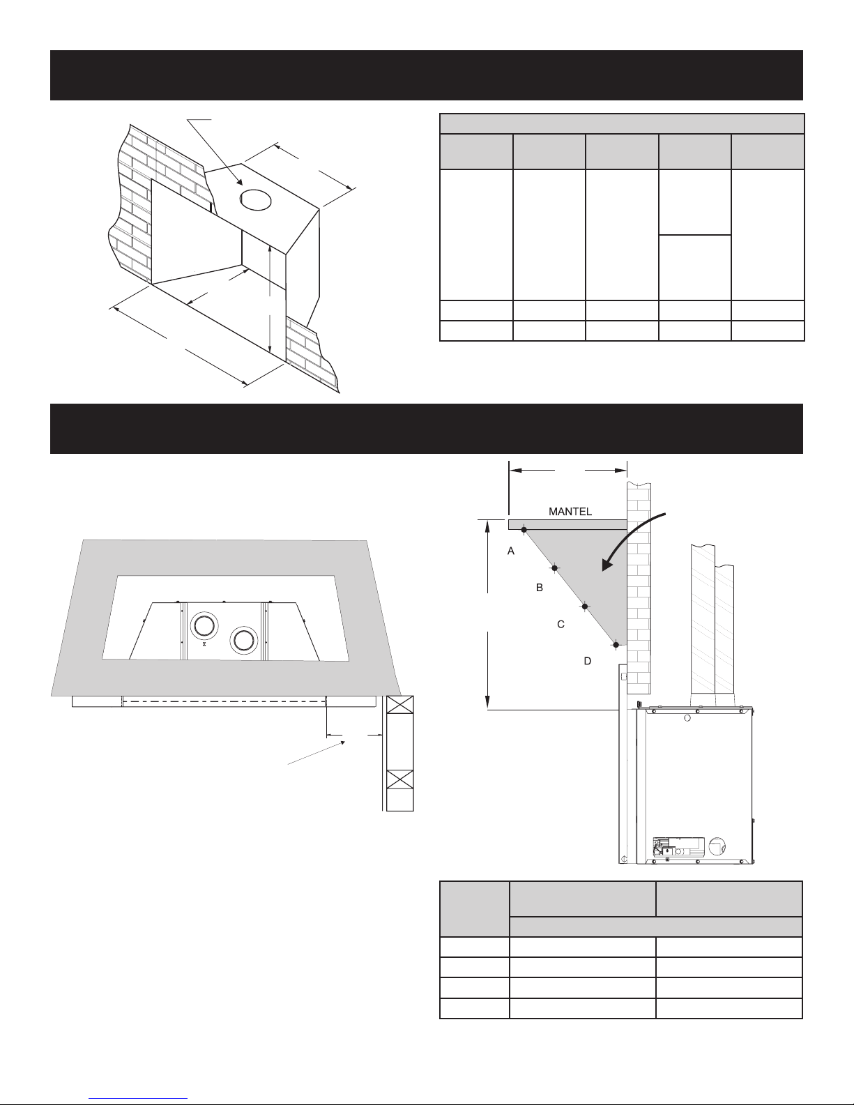
MINIMUM FIREPLACE OPENING DIMENSIONS
TOP OF INSERT
12”
MAX
17”
MIN
COMBUSTIBLE TRIM
AND MANTELS
ALLOWED IN
SHADED AREA
D
C
A
B
MANTEL AND TRIM CLEARANCES
Combustible Material
No greeting cards, stockings or ornamentation of any type should
be placed on or attached to the replace. The ow of heat can
ignite combustibles.
Dimensions (in inches)
Model
No.
DVC20IN 18-1/2 28-1/4
DVC26IN 21-1/2 31-1/4 16-5/8 19
DVC28IN 23-1/2 34-1/4 16-5/8 22
Height
A
Front
Width B
Depth
C
14-7/8
with 1-inch
deep
surround
13-5/8
with 2-1/4
inch deep
surround
Rear
Width D
17-1/4
MINIMUM CLEARANCE TO PERPENDICULAR
(FROM EDGE OF THE BARRIER SCREEN FRAME)
Television Considerations
Installing a television above a replace has become increasingly
popular; however, the area above any replace gets hot and most
TV manufacturers recommend against placing their products
near a heat source.
If you install a television above this replace insert, Empire
Comfort Systems accepts no responsibility for damage or
injuries. Follow the television manufacturer’s installation
instructions, including any recommendations regarding proximity
to heat sources.
If you have a TV above your replace, turn off the replace and
let it cool completely before servicing or touching any buttons on
the TV.
36561-5-0817 Page 11
COMBUSTIBLE SIDE-WALL
Figure 1
8”
Index
Letter
A 9-1/4 16
B 7-1/4 13
C 4-1/2 12
D 1-3/4 8
Mantel Depth From
Fireplace Face
Dimensions in Inches
Figure 2
Distance From
Top of Insert
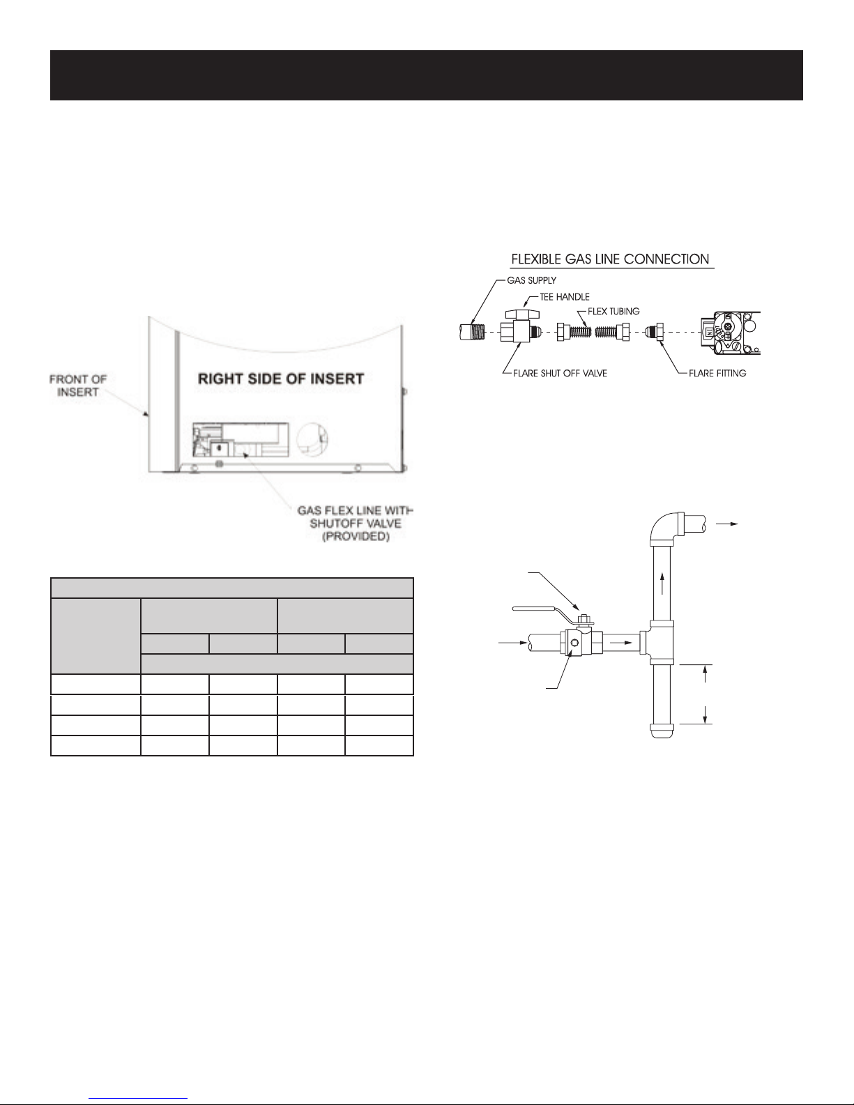
GAS SUPPLY
GAS SUPPL
CONTROL
If the factory-built replace has no gas access hole(s) provided,
an access hole of 1.5 inch (37.5 mm) or less may be drilled
through the lower sides or bottom of the rebox in a proper
workmanship-like manner. This access hole must be plugged
with non-combustible insulation after the gas supply line has
been installed.
The gas pipeline can be brought in through the right or left side of
the appliance. The insert has a Flexline with shutoff valve located
on the right side when facing the unit. See Figures 3 and 4.
Consult the current National Fuel Gas Code, ANSI Z223.1 CAN/
CGA-B149 (.1 or .2) installation code.
NOTICE: Once the gas access hole is drilled through the bottom
of the rebox and through the replace, the replace cannot be
converted back to a solid-fuel burning replace.
Use the following gas connectors:
— ANSI Z21.24 Appliance Connectors of Corrugated Metal
Tubing and Fittings.
— ANSI Z21.45 Assembled Flexible Appliance Connectors of
Other Than All-Metal Construction
The above connectors may be used if acceptable by the authority
having jurisdiction. The Commonwealth of Massachusetts
requires that a exible appliance connector cannot exceed three
feet in length.
Figure 4
Install a gas valve and ground joint union in the gas line upstream
of the gas control to aid in servicing. The National Fuel Gas
Code requires installing a drip leg near the gas inlet. The drip
leg consists of a vertical length of capped pipe installed before
the gas inlet to collect condensation and foreign particles. See
Figure 5.
GAS SUPPLY PLUMBING
TO
VALV E
Figure 3
RECOMMENDED GAS PIPE DIAMETER
Pipe Length
Schedule 40 Pipe
Inside Diameter
NAT Propane NAT Propane
Tubing, Type L
Outside Diameter
(Dimensions in Inches)
0-10ft 1/2 3/8 1/2 3/8
11-40ft 1/2 1/2 5/8 1/2
41-100ft 1/2 1/2 3/4 1/2
101-150ft 3/4 1/2 7/8 3/4
NOTICE: Never use plastic pipe. Check local codes before using
copper tubing or galvanized.
NOTICE: Some municipalities have additional codes. Consult
your local authority and installation code.
MANUAL
SHUT-OFF VALVE
Y
INLET
1/8 NPT PLUGGED
HOLE FOR
TEST GAGE
Figure 5
3”
MINIMUM
36561-5-0817Page 12
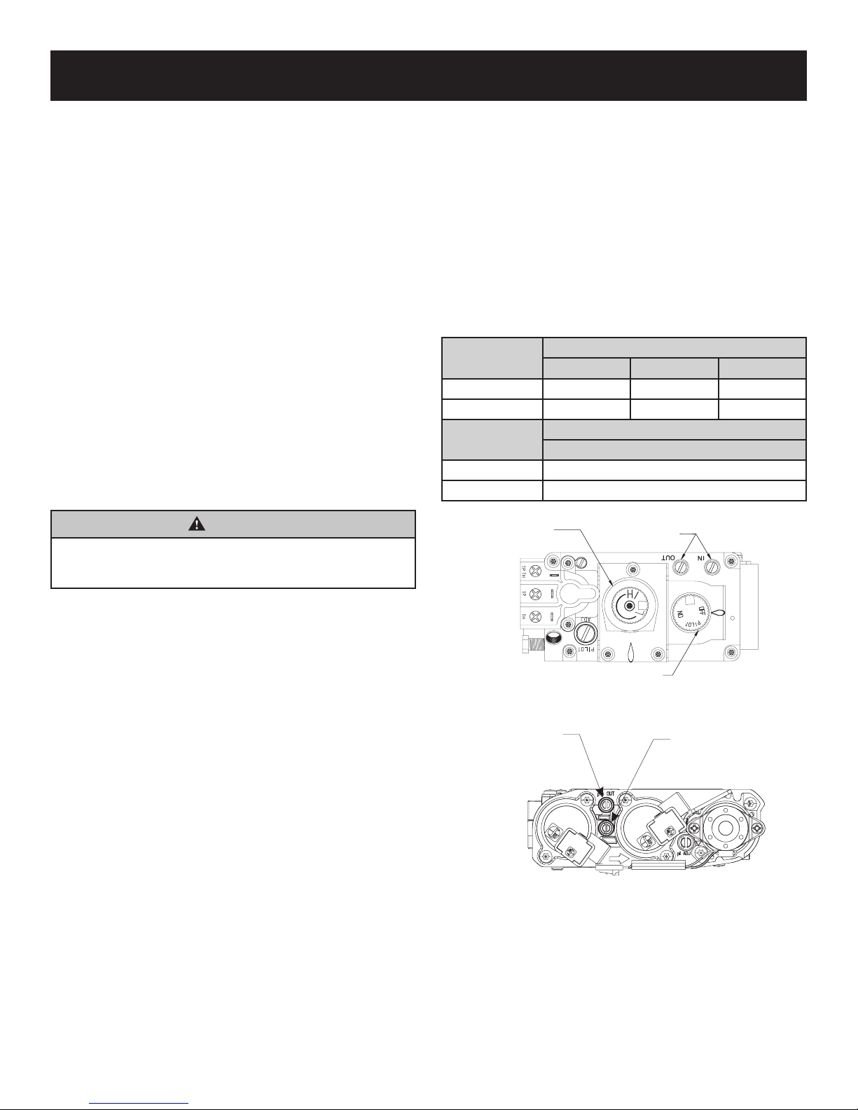
CONTROL KNOB
OUTLET
GAS SUPPLY
Installing a New Main Gas Shut-Off Valve
Each appliance must have its own manual gas shut-off valve
located in the vicinity of the replace. Where none exists, or
where its size or location is not adequate, contact your local
authorized installer for replacement or relocation.
Test for leaks. Turn replace off. Compounds used on threaded
joints of gas piping must be resistant to the action of liqueed
petroleum gases. The installer must check all gas connections
for leaks. Perform all leak tests with a leak test solution or soap
solution. Rinse off all solution once testing is complete. Perform a
pressure test on all unexposed connections.
Never use an exposed ame to check for leaks. Never pressure
test with replace connected; control valve will sustain damage.
Disconnect the replace from piping at the control valve inlet and
cap the pipe before pressure testing.
NOTICE: The millivolt gas controls are equipped with a captured
screw type pressure test point, therefore it is not necessary to
provide a 1/8-inch test point upstream of the control.
When using copper or ex connector use only approved ttings.
Disconnect the appliance and its individual shut-off valve from
the gas supply piping system during any pressure testing of that
system at test pressures in excess of 1/2 psig (3.5kPa).
Isolate the appliance from the gas supply piping system by
closing its manual shut off valve during any pressure testing of
the gas supply piping system at test pressures equal to or less
than 1/2 psig (3.5kPa).
WARNING
If one of the procedures results in pressures in excess of
1/2 psig (14-inch w.c.) (3.5 kPa) on the replace gas valve, it
will result in a hazardous condition.
Checking Manifold Pressures
Both Propane and Natural gas valves have a built-in pressure
regulator in the gas valve.
Natural gas models will have a manifold pressure of
approximately 3.5-inch w.c. (.871kPa) at the valve outlet with
the inlet pressure to the valve from a minimum of 4.5-inch w.c.
(1.120kPa) for the purpose of input adjustment to a maximum of
14.0-inch w.c. (3.484kPa).
Propane models will have a manifold pressure of approximately
10.0-inch w.c. (2.49kPa) at the valve outlet with the inlet pressure
to the valve from a minimum of 10.8-inch w.c. (2.68kPa) for the
purpose of input adjustment to a maximum of 14.0-inch w.c.
(3.484kPa).
Gas Supply Pressure (inches w.c.)
Minimum Normal Maximum
Natural Gas 4.5 7.0 14.0
LP (Propane) 10.8 11.0 14.0
Manifold Pressure (inches w.c.)
Normal (HI)
Natural Gas 3.5
LP (Propane) 10.0
HI/LO
REGULATOR
PRESSURE
TAPS
36561-5-0817 Page 13
PRESSURE
TAP
Figure 6 - Millivolt Valve
INLET
PRESSURE
TAP
Figure 7 - IP Valve
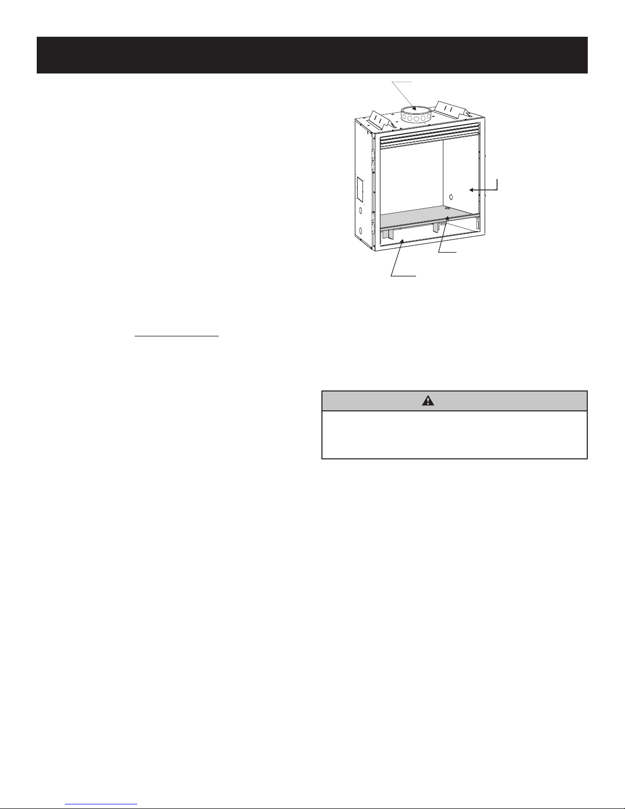
FIREPLACE PREPARATION
ACHED
8” DIAMETER FLUE (MIN.)
GENERIC FACTORY-BUILT WOODBURNING FIREPLACE SHOWN
Before You Start
Before installing, read these instructions and the Vent Kit
Instructions to ensure proper installation. Consult local Building
Codes before beginning the Installation.
NOTICE: Cutting the sheet metal parts of an existing
replace in order to install the replace insert is prohibited.
1. The replace and replace chimney must be cleaned, in
good working order. The approved chimney for the factorybuilt replace or masonry chimney must be used to run
venting through.
NOTICE: Do not handle barrier screen or door assembly with
your bare hands! (Always Wear Gloves)
2. Remove the barrier screen, glass door and log package from
replace insert. Check to make sure there is no damage to
the replace insert or its components.
3. Plan out the gas, venting and electrical route. Start with the
gas line, followed by the chimney preparation and electrical
supply requirements.
4. The minimum replace opening requirements are shown in
Page 11 of this installation manual. The rebrick (refractory),
glass doors, screen rails, screen mesh and log grates can
be removed from a factory built replace to gain minimum
gas insert opening requirements prior to installing the gas
replace insert. See Figure 8.
5. Remove or lock the replace ue damper in the fully open
position prior to installing the gas replace insert.
6. Make sure that all chimney cleanouts t properly so air
cannot leak into the chimney.
7. The replace insert does not require any additional hearth
extension. However, the original hearth materials installed
with the replace must be retained. If the original materials
have been damaged or removed, a new one must be
installed. Hearth materials must consist of a non-combustible
material such as brick, tile, slate, marble, or other noncombustible surface extending the width of the replace and
out a minimum of 16 inches in front. Wood ooring, vinyl, or
carpet are not allowed directly in front of the replace insert.
NOTICE: The original replace cannot be returned to
solid fuel use without returning the hearth extension to the
specication required for a solid fuel replace.
8. The metal oor of the solid fuel rebox may be removed to
install the insert. If the rebox oor is removed, the insert
must be raised off the oor of the replace at least 1/4 inch
to protect the combustible surface under the original
replace. Clearance to combustible material under the insert
is 1/4-inch. Combustible material must not be placed inside
the original area. The side walls and top structure of the
rebox may not be altered with the exception of removable
bafes and dampers. Fire screens, refractory liners (sides
and oor), smoke shields, shelves and bafes may be
removed if attached with mechanical fasteners. The original
replace cannot be returned to solid fuel in this condition.
See Figure 8.
INTERIOR BAFFLES,
SMOKE SHIELDS, AND
SHELVES MAYBE
REMOVED IF ATT
WITH MECHANICAL
FASTENERS
FIREBOX FLOOR
FIREBOX FLOOR
CAN BE REMOVED
CAN BE REMOVED
FIREPLACE FLOOR
CAN NOT BE REMOVED
Figure 8
NOTICE: The following statement is also provided on a
separate warning label plate in the instruction packet. Prior
to installation of the replace insert, the installer must
mechanically secure this warning label plate to the inside of
the replace for future reference as required.
WARNING
This solid fuel replace has been converted for use with gas
only and cannot be used for burning wood or solid fuels
unless all original parts have been replaced and the replace
has been reapproved by the authority having jurisdiction.
Clearances
• Maintain the original specied exterior clearances of the
factory-built replace and vent system.
• Maintain mantel and trim clearances on a masonry replace
at 12 inches above the opening for combustible projections
over 1-1/2 inch.
• Clearances for combustible projections under 1-1/2 inch
must be maintained at 6 inches above the opening per
NFPA211. Plan the surround size accordingly. A surround
must be used with the insert. Under no circumstance can
combustible material be placed behind the surround or
behind the insert!
36561-5-0817Page 14
VENTING
Vent System Installation Precautions
Before installing vent kits, read these instructions and the Vent Kit
Instructions to ensure installation. Consult local Building Codes
before beginning the Installation.
To ensure top performance, safety and efciency, inserts must be
installed with an approved ue liner as per CAN/CGA B-149 or
National Fuel Code ANSI Z223 and these instructions.
WARNING
This gas insert and vent assembly must be vented directly to
the outside and must never be attached to a chimney serving
a separate solid-fuel burning or gas-venting appliance.
Vent System Approvals
Figure 10 shows the vent termination cap and system approved
for use with these models. Approved vent system terminations
are labeled for identication. Use 3-inch diameter, exible
aluminum or stainless steel gas venting for both the incoming
combustion air and exhaust vent pipes. No other venting
systems or components may be used. Detailed installation
instructions are included with each vent termination kit and
should be used in conjunction with this manual.
Horizontal Venting
The vent system on this model CANNOT be terminated
horizontally.
NOTICE: The minimum vertical vent rise is 10 feet and the
maximum vertical vent rise is 35 feet. These dimensions are
measured from the starting collars of the unit to the end of the
last section of vent pipe. See Figure 10.
NOTICE: The damper of the masonry chimney may need to be
removed to install the exible-vent pipe.
When installing into a zero clearance, factory built wood-burning
replace, the DVKI2P Round Vertical Termination Kit should allow
you to mount the vent adaptor and cap to the exposed round
chimney pipe.
NOTICE: The vent cap must be in open, free air. It cannot be
installed under an existing cap shared by other ues.
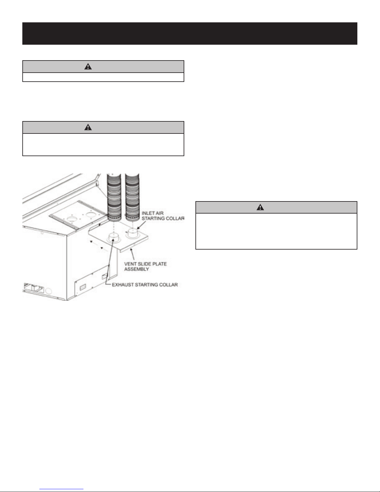
Vertical Venting
The inlet and exhaust vent pipes MUST be connected to the
proper collars on the unit AND to the termination cap or the unit
will not operate. The intake vent collar is identied by a stamped
“I” on the top collar sliding vent plate assembly.
WARNING
Major U.S. building codes specify minimum chimney and/or
vent height above the roof top. These minimum heights are
necessary in the interest of safety. See Figures 11 and 12 for
minimum heights, provided the termination cap is at least 2
feet from a vertical wall and 2 feet below a horizontal overhang.
NOTICE: The above warning also pertains to vertical vent
systems installed on the outside of the building.
WARNING
The exhaust pipe must only be connected to the exhaust
starting collar of the unit and to the exhaust collar of the
termination cap.
The inlet air pipe must only be connected to the inlet air
starting collar of the unit and to the inlet air collar of the
termination cap. Both the inlet vent and the ue vent must
be connected from the insert to the vent termination cap.
36561-5-0817 Page 15
INSTALLATION
Connect the Vent Pipe & Install the Fireplace Insert
CAUTION
Sharp edges. Wear gloves when installing.
1. Install the 3-inch exible vent pipes down through the
chimney.
2. Attach the pipe-to-cap adaptor to the termination cap and the
top of the exible vent pipe, then install the cap to the top of
the chimney.
CAUTION
Seal off the area between the termination cap and the top
of the solid-fuel chimney opening into which the vent cap
is installed to avoid downdrafts and/or cold air problems.
3. Remove the vent slide plate assembly from the top of the
insert. See Figure 9.
9. Level the insert from side to side and front to back.
10. If necessary, use the leveling bolts included in the instruction
pack. Screw the legs into the nuts installed in the bottom of
the insert. Turn legs in until insert is level.
NOTICE: If desired, attach metal strapping or brackets
(not provided) from the replace cavity to the insert outer
jacket to secure the replace insert to the replace hearth or
opening.
11. Once the replace insert is level and the vent slide plate is
close to seating, install the black button head 5/16-18 x 2
1/2 inch long bolt through the center hole of the insert top
bracket, and into the vent slide plate nut.
12. Use the provided allen wrench to tighten the bolt until the
vent slide plate is seated forward completely.
13. Install surround assembly. Refer to instructions included with
the surround kit.
NOTICE: All manufacturer supplied surrounds, shrouds, and
decorative front options have been tested and are approved for
use with the replace insert and may cover existing air circulation
vents or grills on the solid fuel replace it is installed into.
Do not seal the ventilation openings on the insert with trim panels
or surrounds.
WARNING
Only surrounds, shrouds, and decorative front components
supplied by the manufacturer may be used to cover
integral grills on the solid-fuel burning replace. No other
components such as sheet metal plates may be used to
seal off vents.
Figure 9
4. Trim off excess venting then attach and secure the bottom
ends of the ex pipes to the starting collars with the
adjustable band clamps provided.
5. Slide the gas insert into place without the surround panels
attached, and position any excess ex vent pipe back up
into the chimney. Do not leave an excess of pipe that could
cause a restriction in the intake or exhaust system.
6. Make all gas and electrical connections.
7. Align the vent slide plate assembly with the guides located
on top of the insert.
8. Work the insert inch by inch into the replace cavity as you
pull forward on the vent slide plate assembly. Do not use
excessive force on the vent slide plate.
NOTICE: The front anges of the insert (without the surround)
should be set at approximately 1-inch) in front of the face of the
replace.
36561-5-0817Page 16
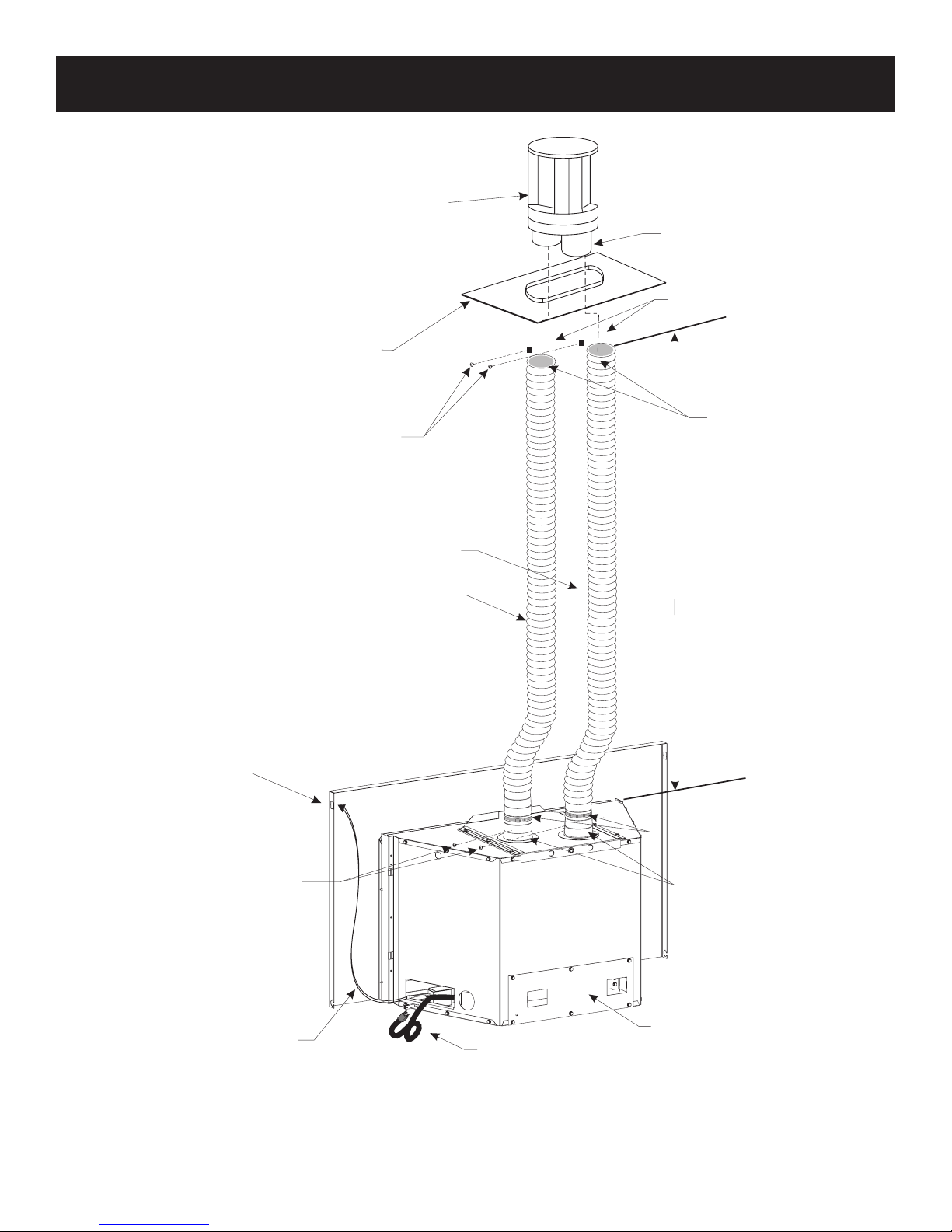
INSTALLATION DIAGRAM
ROUND
TERMINATION CAP
DVKI2P KIT
(INCLUDES CO-AXIAL
ADAPTER AND FLASHING)
DVKI2P FLASHING SHOWN. IF A
LARGER OR DIFFERENT CONFIGURATION
IS REQUIRED, A FIELD-BUILT VERSION
(BUILT TO LOCAL CODES) IS ACCEPTABLE.
INSTALL RETAINER SCREWS
THROUGH THE VENT CLAMPS
TO SECURE VENTING
NOTE: LONG EXTENSION
TUBE FOR INLET
CONNECTION
VENT CLAMPS
USE HIGH-TEMP
SEALANT ON VENT
CONNECTIONS
OPTIONAL ON/OFF
SWITCH LOCATION
INSTALL SCREWS THROUGH
VENT CLAMPS TO SECURE
THE VENTING TO THE COLLARS
INTAKE VENT
10’ MINIMUM
35’ MAXIMUM
FLUE EXHAUST VENT
VENT CLAMPS
USE HIGH-TEMP
SEALANT ON VENT
CONNECTIONS
OPTIONAL
LOW-VOLTAGE
WIRES
36561-5-0817 Page 17
BLOWER
POWER CORD
Figure 10
BLOWER ACCESS
PLATE
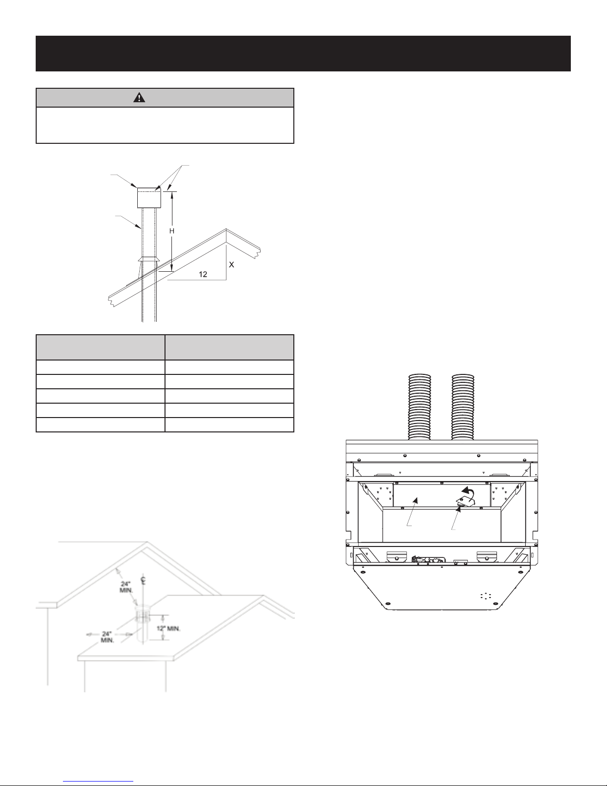
VERTICAL TERMINATION
Determining Minimum Vent Height Above the Roof.
WARNING
Major U.S. building codes specify minimum chimney height
above the roof top. These specications are summarized in
Figure 11.
LOWEST
VENTCAP
WOOD BURNING
CHIMNEY
ROOF PITCH X/12
H (Min.) Minimum height from
roof to lowest discharge opening
ROOF PITCH
Flat to 6/12 12
6/12 to 7/12 15
Over 7/12 to 8/12 18
Over 8/12 to 16/12 24
Over 16/12 to 21/12 36
Figure 11
DISCHARGE
OPENING
H (Min.)
(in inches)
Vertical Applications
The Gas Fireplace Insert has been approved for vertical
installations up to 35 feet in height (top of insert to cap).
General Maintenance
Conduct an inspection of the venting system semi-annually.
Recommended areas to inspect are as follows:
1. Check areas of the venting system which are exposed to
the elements for corrosion. These will appear as rust spots
or streaks and, in extreme cases, holes. These components
should immediately be replaced.
2. Remove the cap and shine a ashlight down the vent.
Remove any bird nests or other foreign material.
3. Check for evidence of excessive condensate, such as water
droplets forming in the ex venting and subsequently dripping
out at joints or seams. Condensate can cause corrosion of
caps, pipe and ttings. It may be caused by having excessive
runs, or having exterior portions of the system exposed to
cold weather.
4. Inspect joints to verify that no pipe sections or ttings
have been disturbed and, consequently, loosened. Check
mechanical supports.
Tall Vent Heights
Poor combustion may occur during initial and cold start-ups.
Open the ue bafe vent to improve performance. To adjust,
rotate the ue bafe vent enough to encourage better draft for
improved combustion.
NOTICE: For steep roof pitches, the vent height must be
increased. In high wind conditions, nearby trees, adjoining roof
lines, steep pitched roofs, and other similar factors can result in
poor draft, or down-drafting. In these cases, increasing the vent
height may solve this problem.
When terminating the vent cap near an exterior wall or overhang,
maintain minimum clearances as shown in Figure 12.
Figure 12
FIREBOX
BAFFLE
Figure 13
FLUE
BAFFLE
VENT
36561-5-0817Page 18
VERTICAL TERMINATION
ON/OFF SWITCH
Optional Inlet Air Restrictor Plate Installation
An optional air restrictor plate is included in the instruction
packet. Install the optional air restrictor if the replace insert
installation requires 20 to 35 feet vertical venting, or is in highwind area.
1. Remove the barrier screen, glass door, log set and liner
panels (if applicable) and set aside.
2. Remove the back log support bracket by removing the two
screws securing it to the log support and set aside.
3. Remove the log support by removing the three screws
securing it to the rebox back and set aside.
4. Loosen the two bottom screws that secure the inlet air duct
collar at the rear of the rebox. See Figure 14.
5. Place the inlet air restrictor plate over the air intake opening.
Align the plate with the loosened screws, shift the plate on
the keyhole slots, then retighten the two screws. See Figure
14 for locating the inlet air duct opening.
6. Reinstall the back log support and three screws removed in
step 3.
7. Reinstall the rear log support bracket and two screws
removed in step 2.
8. If applicable, reinstall liner panels, log set, glass door, and
barrier screen.
Figure 14
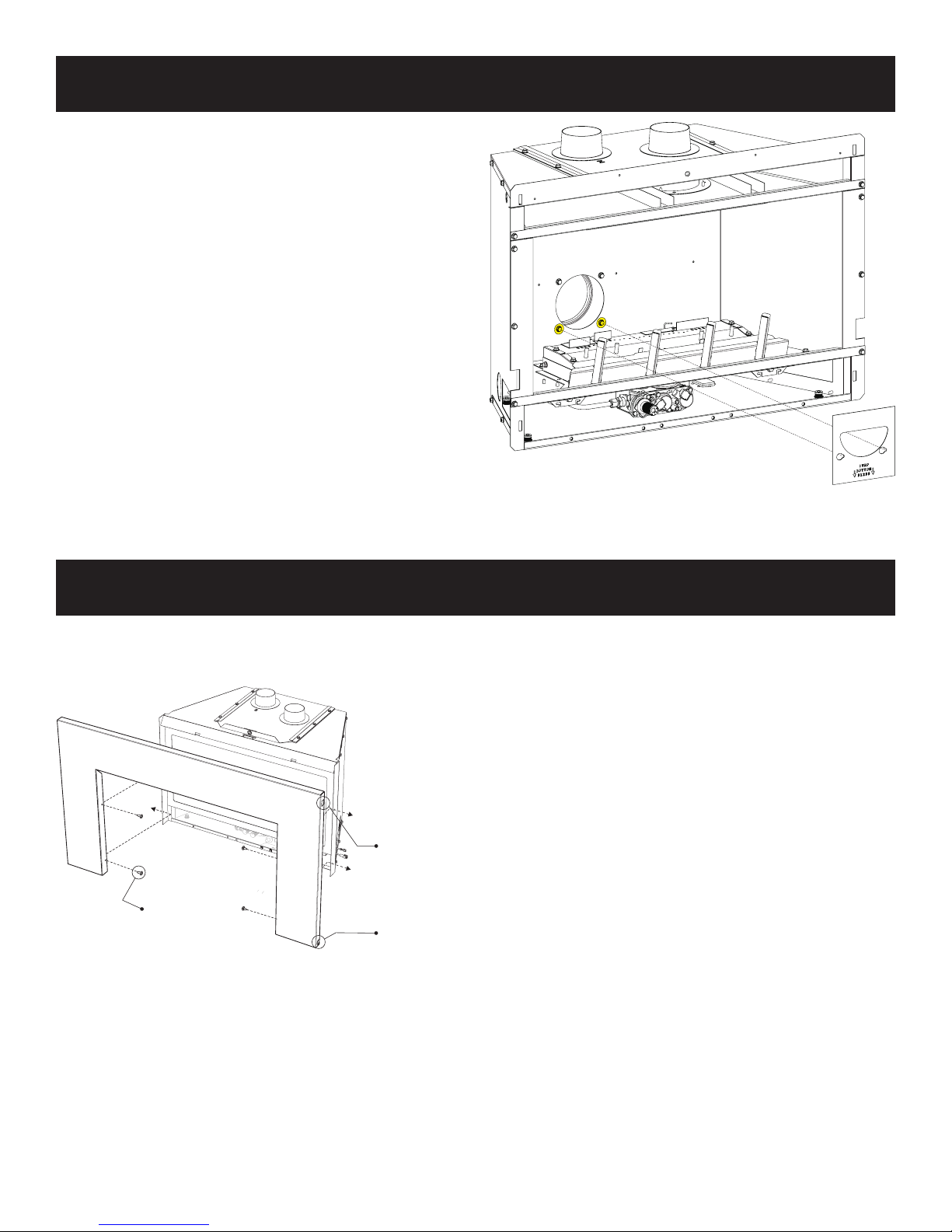
SURROUND INSTALLATION
1. Secure the surround to the replace insert anges with four #8
x 1/2-inch truss head screws (two each side). See Figure 15.
KNOCKOUT
#
1
8/TRUSS HD
x
2
SCREWS (4)
Figure 15
POWER CORD
KNOCKOUT
36561-5-0817 Page 19
 Loading...