

Empire Comfort Systems DV-55E-3 Installation Instructions And Owner's Manual
INSTALLATION INSTRUCTIONS
AND
OWNER'S MANUAL
FAN TYPE
DIRECT VENT
WALL FURNACE
For Installation in
Manufactured (Mobile Home),
Modular or Residential Homes
Patent #5.664.555
WARNING: If the information in
this manual is not followed exactly , a
fire or explosion may result causing
property damage, personal injury or
loss of life.
— Do not store or use gasoline or other
flammable vapors and liquids in the
vicinity of this or any other appliance.
— WHA T T O DO IF YOU SMELL GAS
• Do not try to light any appliance.
• Do not touch any electrical switch;
do not use any phone in your
building.
• Immediately call your gas supplier
from a neighbor's phone. Follow
the gas supplier's instructions.
• If you cannot reach your gas
supplier, call the fire department.
— Installation and service must be
performed by a qualified installer,
service agency or the gas supplier.
MODEL
DV-55E-3
EFFECTIVE DATE
APRIL, 2001
WARNING: If not installed, operated
and maintained in accordance with the
manufacturer's instructions, this
product could expose you to substances
in fuel or from fuel combustion which
can cause death or serious illness.
R-3119 Page 1

TABLE OF CONTENTS
Lighting Instructions ...................................................................................................................... 3
Gas Conversion Instructions........................................................................................................... 4
Liquefied Petroleum (Propane) Safety Information ....................................................................... 5
Specifications and Requirements.................................................................................................... 6
Installation
Location ........................................................................................................................... 6,7
Venting ............................................................................................................................ 7,8
Gas Supply.......................................................................................................................... 8
Appliance Maintenance Information for Qualified Service Person ............................................... 9
Maintenance Operation and Troubleshooting Guide.................................................................... 10
Control Board — Diagnostics ...................................................................................................... 10
Wiring Diagrams .......................................................................................................................... 11
Parts List ....................................................................................................................................... 12
Parts View of Furnace .................................................................................................................. 13
THIS IS A HEATING APPLIANCE
DO NOT OPERATE THIS APPLIANCE WITHOUT FRONT PANEL INSTALLED.
• Due to high temperatures the appliance should be
located out of traffic and away from furniture and
draperies.
• Children and adults should be alerted to the hazards
of high surface temperatures and should stay away to
avoid burns or clothing ignition.
• Young children should be carefully supervised when
they are in the same room as the appliance.
• Clothing or other flammable material should not be
placed on or near the appliance.
• Any safety screen or guard removed for servicing an
appliance must be replaced prior to operating the
appliance.
• Keep burner and control compartment clean.
• Vent cap hot while furnace is in operation.
• Installation and repair should be done by a
QUALIFIED SERVICE PERSON. The appliance
should be inspected before use and at least annually
by a qualified service person. More frequent cleaning
may be required due to excessive lint from carpeting,
bedding materials, etc. It is imperative that control
compartments, burners and circulating air
passageways of the appliance be kept clean.
• DO NOT put anything around the furnace that will
obstruct the flow of combustion and ventilation air.
• DO keep the appliance area clear and free from
combustible material, gasoline and other flammable
vapors and liquids.
• DO examine venting system periodically and replace
damaged parts.
• DO make a periodic visual check of burner. Clean
and replace damaged parts.
• DO NOT use this heater if any part has been under
water. Immediately call a qualified service technician
to inspect the heater and to replace any part of the
control system and any gas control which has been
under water.
Page 2
R-3119
FOR YOUR SAFETY READ BEFORE OPERATING
WARNING: If you do not follow these instructions exactly, a fire or explosion may result
causing property damage, personal injury or loss of life.
A. This appliance does not have a pilot. It is equipped with
an ignition device which automatically lights the burner.
Do not try to light the burner by hand.
B. BEFORE OPERATING smell all around the appliance
area for gas. Be sure to smell next to the floor because
some gas is heavier than air and will settle on the floor.
WHAT TO DO IF YOU SMELL GAS
• Do not try to light any appliance.
• Do not touch any electrical switch;
do not use any phone in your building.
• Immediately call your gas supplier from a neighbor's phone. Follow the gas supplier's instructions.
OPERATING INSTRUCTIONS
1. STOP! Read the safety information above.
2. Set the thermostat to lowest setting.
3. Turn off all electric power to the appliance.
4. This appliance is equipped with an ignition device
which automatically lights the burner. Do not try to
light the burner by hand.
VINYL CAP
CONVERTIBLE
REGULATOR
GAS CONTROL LEVER SHOWN
IN "OFF" POSITION
OFF
• If you cannot reach your gas supplier, call the fire
department.
C. Use only your hand to push in or turn the gas control
knob. Never use tools. If the knob will not push in
or turn by hand, don't try to repair it; call a
qualified service technician. Force or attempted
repair may result in a fire or explosion.
D. Do not use this appliance if any part has been under
water. Immediately call a qualified service technician to inspect the appliance and to replace any part
of the control system and any gas control which has
been under water.
5. Remove control access panel (front panel).
6. Turn gas control knob clockwise to "OFF."
7. Wait ten (10) minutes to clear out any gas. Then
smell for gas, including near the floor. If you smell
gas, STOP! Follow "B" in the safety information
above. If you don't smell gas, go to the next step.
8. Turn gas control knob counterclockwise to
"ON".
9. Replace control access panel (front panel).
10. Turn on all electric power to the appliance.
11. Set thermostat to desired setting.
TOP VIEW
TO TURN OFF GAS TO APPLIANCE
1. Set the thermostat to lowest setting.
2. Turn off all electric power to the appliance if service
is to be performed .
3. Remove control access panel (front panel).
R-3119 Page 3
12. If the appliance will not operate, follow the instructions "TO TURN OFF GAS TO APPLIANCE" and
call your service technician or gas supplier.
BACK END VIEW
4. Turn gas control knob clockwise to "OFF."
Do not force.
5. Replace control access panel (front panel).

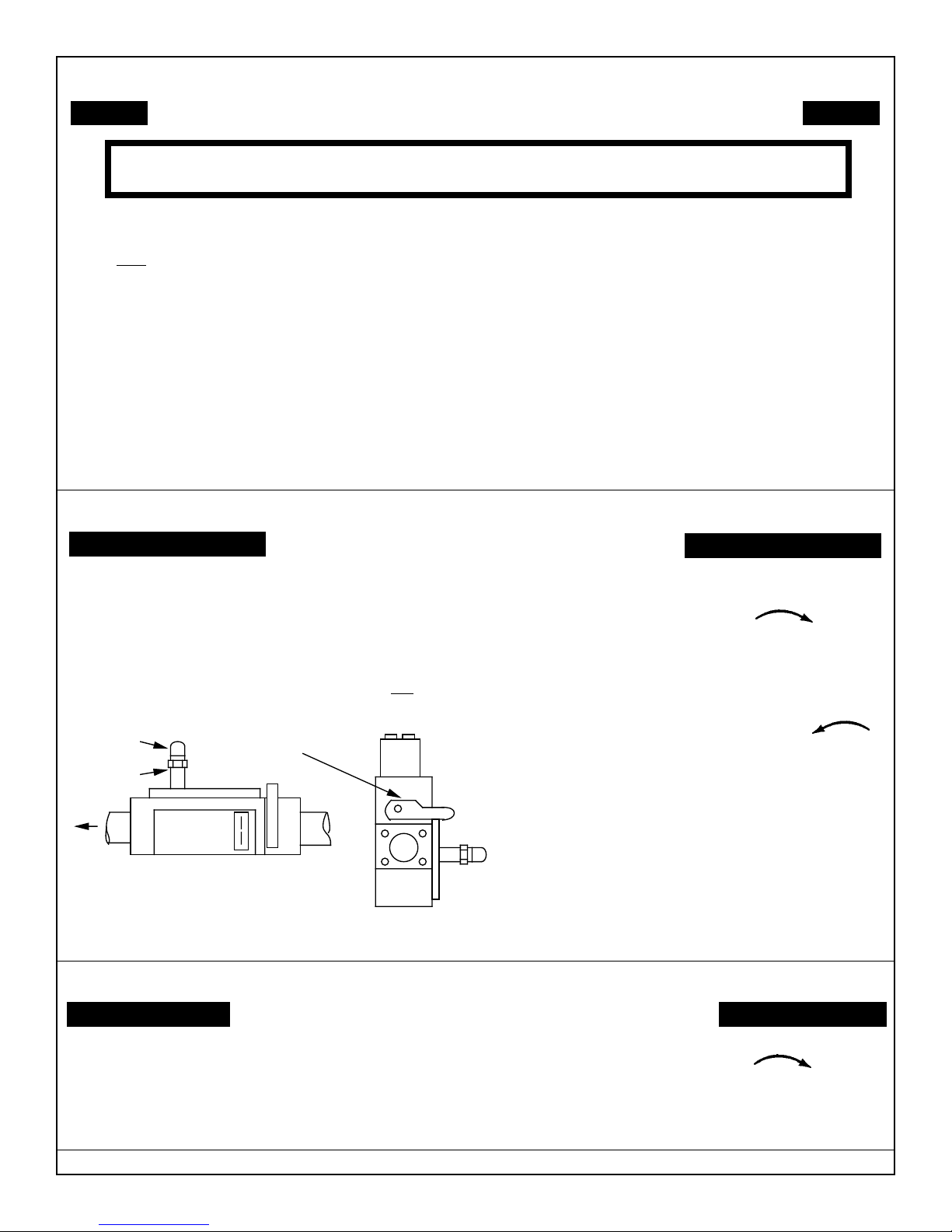
GAS CONVERSION INSTRUCTIONS
BACK END VIEW
GAS CONTROL LEVER SHOWN
IN "OFF" POSITION
OFF
TOP VIEW
CONVERTIBLE
REGULATOR
VINYL CAP
GAS VALVE-LP
RED LP RING
Warning: Conversion must be done by a qualified service technician. Main burner orifice(s) and new
gas conversion label are provided in conversion kit attached to manifold pipe.
CONVERSION INSTRUCTIONS FROM (LP) PROPANE GAS TO NATURAL GAS
1. Make sure gas supply to furnace is off prior to conversion and disconnect electrical power to unit.
2. Open brass union located between the gas valve and burner box.
Remove the 4 mounting screws securing manifold plate to the
burner box. Remove the top 2 screws holding the burner box top in
place and then remove the 1 screw holding the end of the manifold
pipe in place. Grasp union and remove manifold pipe.
3. Remove (1) LP gas main burner orifice marked 55 for DV-20E, (2)
VINYL CAP
CONVERTIBLE
REGULATOR
LP gas main burner orifices marked 55 for DV-40E or (3) LP gas
main burner orifices marked 1.20mm for DV-55E located in the
manifold pipe and replace with (1) Natural gas main burner orifice
marked 44 for DV-20E, (2) Natural gas main burner orifices
marked 44 for DV-40E or (3) Natural gas main burner orifices
marked 47 for DV-55E supplied in conversion kit.
4. Replace manifold pipe being sure to locate orifice(s) in the end of the burner. Secure the manifold and top burner box cover
in place using the screws earlier removed. Reconnect the brass union.
5. Remove the vinyl cap and unscrew the gas control convertible regulator and reverse to Natural gas side and screw back
into place. The red LP ring will be up just under the vinyl cap. Reattach vinyl cap. Refer to figure illustrating the gas
valve.
6. Place LP gas main burner orifice(s) in conversion kit. Attach conversion kit to manifold pipe. Attach new label to unit
nameplate indicating that the unit was converted to Natural gas.
7. Turn on gas supply to furnace and check all gas connections for leaks with soap solution, watching for bubbles on all gas
connections.
8. Turn on electrical power to unit and turn on furnace to verify proper operation. It may take several tries for ignition to
completely purge all the air from the gas line.
GAS CONTROL LEVER SHOWN
IN "OFF" POSITION
RED LP RING
TOP VIEW
GAS VALVE-NATURAL
OFF
BACK END VIEW
Warning: Conversion must be done by a qualified service technician. Main burner orifice(s) and new
gas conversion label are provided in conversion kit attached to manifold pipe.
CONVERSION INSTRUCTIONS FROM NATURAL GAS TO (LP) PROPANE GAS
1. Make sure gas supply to furnace is off prior to conversion and disconnect electrical power to unit.
2. Open brass union located between the gas valve and burner box.
Remove the 4 mounting screws securing manifold plate to the
burner box. Remove the top 2 screws holding the burner box top in
place and then remove the 1 screw holding the end of the manifold
pipe in place. Grasp union and remove manifold pipe.
3. Remove (1) Natural gas main burner orifice marked 44 for DV-20E,
(2) Natural gas main burner orifices marked 44 for DV-40E or (3)
Natural gas main burner orifices marked 47 for DV-55E located in
the manifold pipe and replace with (1) LP gas main burner orifice
marked 55 for DV-20E, (2) LP gas main burner orifices marked 55
for DV-40E or (3) LP gas main burner orifices marked 1.20mm for
DV-55E supplied in conversion kit.
4. Replace manifold pipe being sure to locate orifice(s) in the end of the burner. Secure the manifold and top burner box cover
in place using the screws earlier removed. Reconnect the brass union.
5. Remove the vinyl cap and unscrew the gas control convertible regulator and reverse to LP gas side (red ring on regulator)
and screw back into place. Reattach vinyl cap. Refer to figure illustrating the gas valve.
6. Place Natural gas main burner orifice(s) in conversion kit. Attach conversion kit to manifold pipe. Attach new label to
unit nameplate indicating that the unit was converted to LP gas.
7. Turn on gas supply to furnace and check all gas connections for leaks with soap solution, watching for bubbles on all gas
connections.
8. Turn on electrical power to unit and turn on furnace to verify proper operation. It may take several tries for ignition to
completely purge all the air from the gas line.
Page 4
R-3119
 Loading...