

Empire Comfort Systems DV25IN33LN-3, DV25IN73LN-1, DV25IN73LP-1, DV33IN33LN-4, DV35IN33LP-4 Installation Instructions And Owner's Manual
...
INSTALLATION INSTRUCTIONS
AND OWNER’S MANUAL
INSTALLER: Leave this manual with the appliance.
CONSUMER: Retain this manual for future reference.
WARNING: If not installed, operated and maintained
in accordance with the manufacturer’s instructions,
this product could expose you to substances in fuel
or from fuel combustion which can cause death or
serious illness.
WARNING
FIRE OR EXPLOSION HAZARD
Failure to follow safety warnings exactly
could result in serious injury, death or
property damage.
— Do not store or use gasoline or other am-
mable vapors and liquids in the vicinity of
this or any other appliance.
— WHAT TO DO IF YOU SMELL GAS
• Do not try to light any appliance.
• Do not touch any electrical switch; do
not use any phone in your building.
• Leave the building immediately.
• Immediately call your gas supplier
from a neighbor’s phone. Follow the
gas supplier’s instructions.
• If you cannot reach your gas supplier,
call the re department.
— Installation and service must be per-
formed by a qualied installer, service
agency or the gas supplier.
DIRECT VENT
GAS FIREPLACE HEATER
FIREPLACE INSERT MODELS
DV25IN33L(N,P)-3
GAS-FIRED
DV25IN73L(N,P)-1
DV(33,35)IN33L(N,P)-4
DV(33,35)IN73L(N,P)-2
UL FILE NO. MH30033
This appliance may be installed in
an aftermarket, permanently located,
manufactured home (USA only) or mobile
home, where not prohibited by state or local
codes.
This appliance is only for use with the type
of gas indicated on the rating plate. This
appliance is not convertible for use with other
gases, unless a certied kit is used.
WARNING
HOT GLASS
CAUSE BURNS.
DO NOT TOUCH
UNTIL COOLED.
NEVER
A barrier designed to reduce the risk of burns from the
hot viewing glass is provided with this appliance and shall
be installed for the protection of children and other at-risk
individuals.
Note: Barrier required, may be sold separately.
ALLOW CHILDREN
TO TOUCH GLASS.
WILL
GLASS
Page 1

TABLE OF CONTENTS
SECTION PAGE
Specications ..................................................................................................................... 3
Accessories ........................................................................................................................ 4
Important Safety Information ........................................................................................... 5-6
Safety Information for Users of LP-Gas ............................................................................. 7
Introduction ........................................................................................................................ 8
Fireplace Insert Dimensions .............................................................................................. 9
Mantel and Trim Clearances ............................................................................................ 10
Gas Supply ................................................................................................................. 11-12
Venting and Installation ............................................................................................... 13-15
Vertical Termination .....................................................................................................16-17
Alternate On/Off Switch Installation .................................................................................18
Blower Accessory Information .......................................................................................... 19
Log Identication...............................................................................................................20
Log Placement ............................................................................................................21-29
Operating Instructions ...................................................................................................... 30
Standing Pilot Lighting Instructions .................................................................................. 31
Standing Pilot Wiring ........................................................................................................ 32
Standing Pilot Troubleshooting ........................................................................................ 33
IPI Electronic System Operating Instructions ................................................................... 34
IPI Electronic System Wiring Diagram ............................................................................. 35
Intermittent Pilot Lighting Instructions .............................................................................. 36
Intermittent Control System Troubleshooting .............................................................. 37-39
Insert Maintenance and Service ...................................................................................... 40
Insert Parts View .............................................................................................................. 41
Insert Parts List ...........................................................................................................42-43
Master Parts Distributor List ............................................................................................. 44
How To Order Repair Parts .............................................................................................. 44
Warranty ...........................................................................................................................45
Appliance Service History............................................................................................46-47
35657-4-1015Page 2
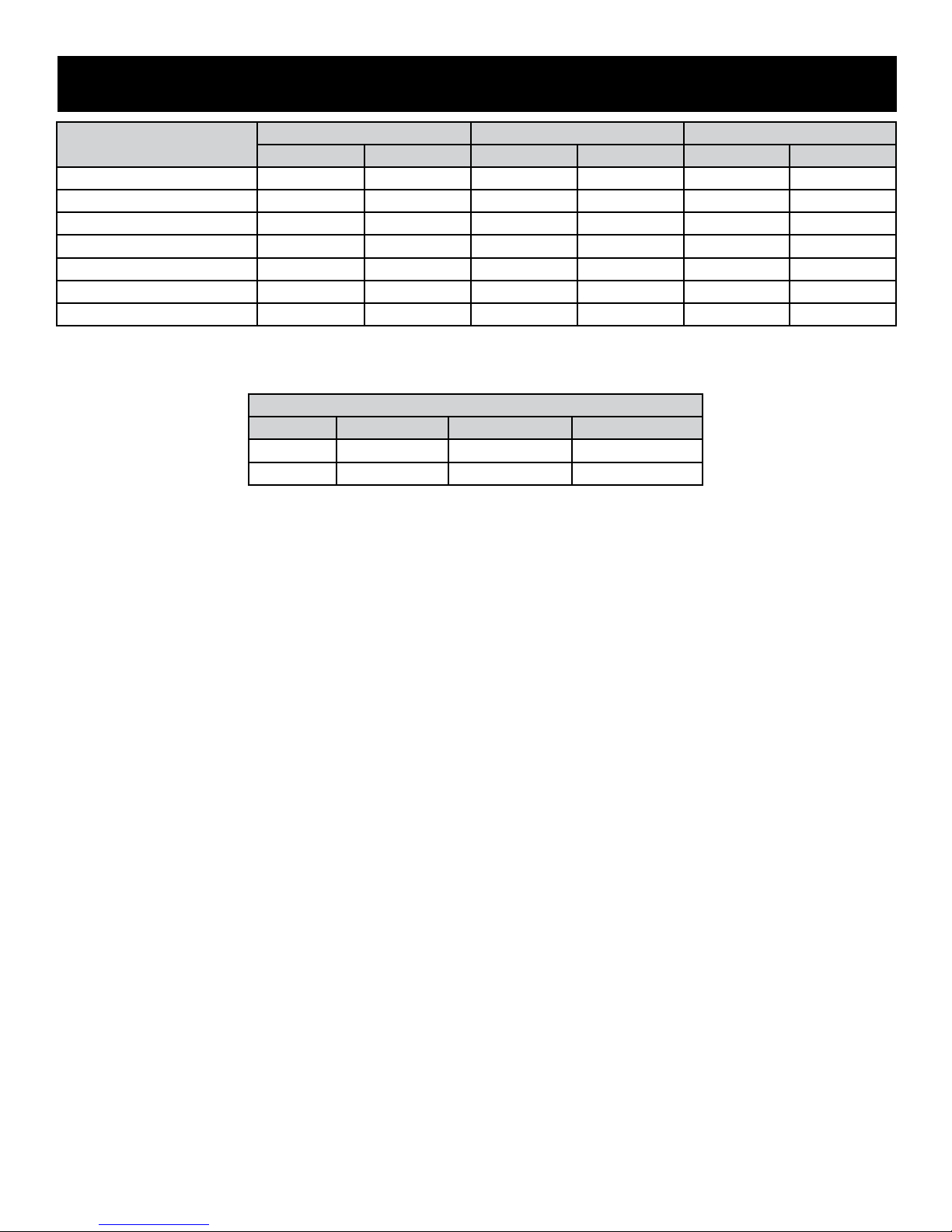
SPECIFICATIONS
DV25IN(3,7)3L DV33IN(3,7)3L DV35IN(3,7)3L
LP NAT LP NAT LP NAT
Input BTU/Hr Maximum 25,000 25,000 33,000 33,000 35,000 35,000
Input BTU/Hr Minimum 17,000 17,000 25,000 23,000 27,000 25,000
KWH (Maximum) 7.3 7.3 9.57 9.57 10.15 10.15
KWH (Minimum) 5 5 7.30 6.67 7.83 7.30
Orice #53 (0.0596) #42 (0.0935) 1.55mm #36 (0.1065) 1.65mm (0.65) #35 (.110)
Air Shutter Opening Full Open 1/8” Full Open 1/4” Full Open 1/4”
Gas Inlet Shutoff Valve (pipe) 1/2 NPT 1/2 NPT 1/2 NPT 1/2 NPT 1/2 NPT 1/2 NPT
NOTE: Air shutter settings are factory minimum settings. Some venting congurations may require minor air shutter adjustments for
optimum performance.
GAS SUPPLY PRESSURES
GAS TYPE MAXIMUM MINIMUM MANIFOLD
NAT 14 4.5 3.5
LP 14 11 10
35657-4-1015 Page 3
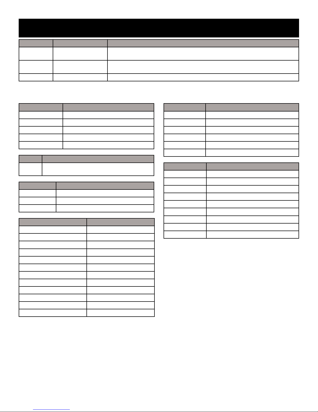
ACCESSORIES
Venting Kits Description Contents
DVKI Vertical Vent Kit 17 1/2’
DVVK3FV Vertical Vent Kit 25’
DVK35 Vent Extension Kit 35’ ex vent extension section with 2 connectors and 4 clamps
NOTICE: When installing vent caps, special locally made ashings may be required to properly seal the vent system to the existing
chimney termination.
One piece of 35’ FlexVent (split for 17 1/2’ vent run), Round Cap, Flashing, connectors,
and clamps. Recommended when installing to an existing round replace chimney pipe.
Two pieces of 25’ FlexVent, Rectangle Cap, Flashing, connectors, and clamps Recommended when installing to a square or rectangular clay ue.
Remote Controls Description
FRBC Millivolt Battery Remote ON/OFF
FRBTC Millivolt Battery Remote Thermostat
TRW Millivolt WIRELESS Wall Thermostat
TMV Millivolt Reed Switch Wall Thermostat
FWS-1 Millivolt Wall Switch
Shroud Description
SH1BL Shroud, Black (For replace openings up to 48”x
36” - Requires a surround)
Barrier Screen Description
DVFQ25TBL Barrier screen for DV25IN series
DVFQ33TBL Barrier screen for DV33IN series
DVFQ35TBL Barrier screen for DV35IN series
Surround Kit Description
DS2563DBL Steel Surround, 6 x 3 in.
DS3363DBL Steel Surround, 6 x 3 in.
DS3563DBL Steel Surround, 6 x 3 in.
DS2566DBL Steel Surround, 6 x 6 in.
DS3366DBL Steel Surround, 6 x 6 in.
DS3566DBL Steel Surround, 6 x 6 in.
S256VBL Surround 3-sided, 1-piece
S336VBL Surround 3-sided, 1-piece
S356VBL Surround 3-sided, 1-piece
SC256BL Cast Iron Surround, 6 inch
SC336BL Cast Iron Surround, 6 inch
SC356BL Cast Iron Surround, 6 inch
Surround Cover Description
C253DBL Surround Bottom Cover (3” Side Panels)
C333DBL Surround Bottom Cover (3” Side Panels)
C353DBL Surround Bottom Cover (3” Side Panels)
C256DBL Surround Bottom Cover (6” Side Panels)
C336DBL Surround Bottom Cover (6” Side Panels)
C356DBL Surround Bottom Cover (6” Side Panels)
Decorative Front Description
DVFQ25HBL Lancaster Front - Black
DVFQ25HHP Lancaster Front - Hammered Pewter
DVFQ25HSS Lancaster Front - Stainless Steel
DVFQ33HBL Lancaster Front - Black
DVFQ33HHP Lancaster Front - Hammered Pewter
DVFQ33HSS Lancaster Front - Stainless Steel
DVFQ35HBL Lancaster Front - Black
DVFQ35HHP Lancaster Front - Hammered Pewter
DVFQ35HSS Lancaster Front - Stainless Steel
A barrier designed to reduce the risk of burns from the hot viewing
glass is required for use with this appliance and must be installed
for the protection of children and other at-risk individuals.
35657-4-1015Page 4
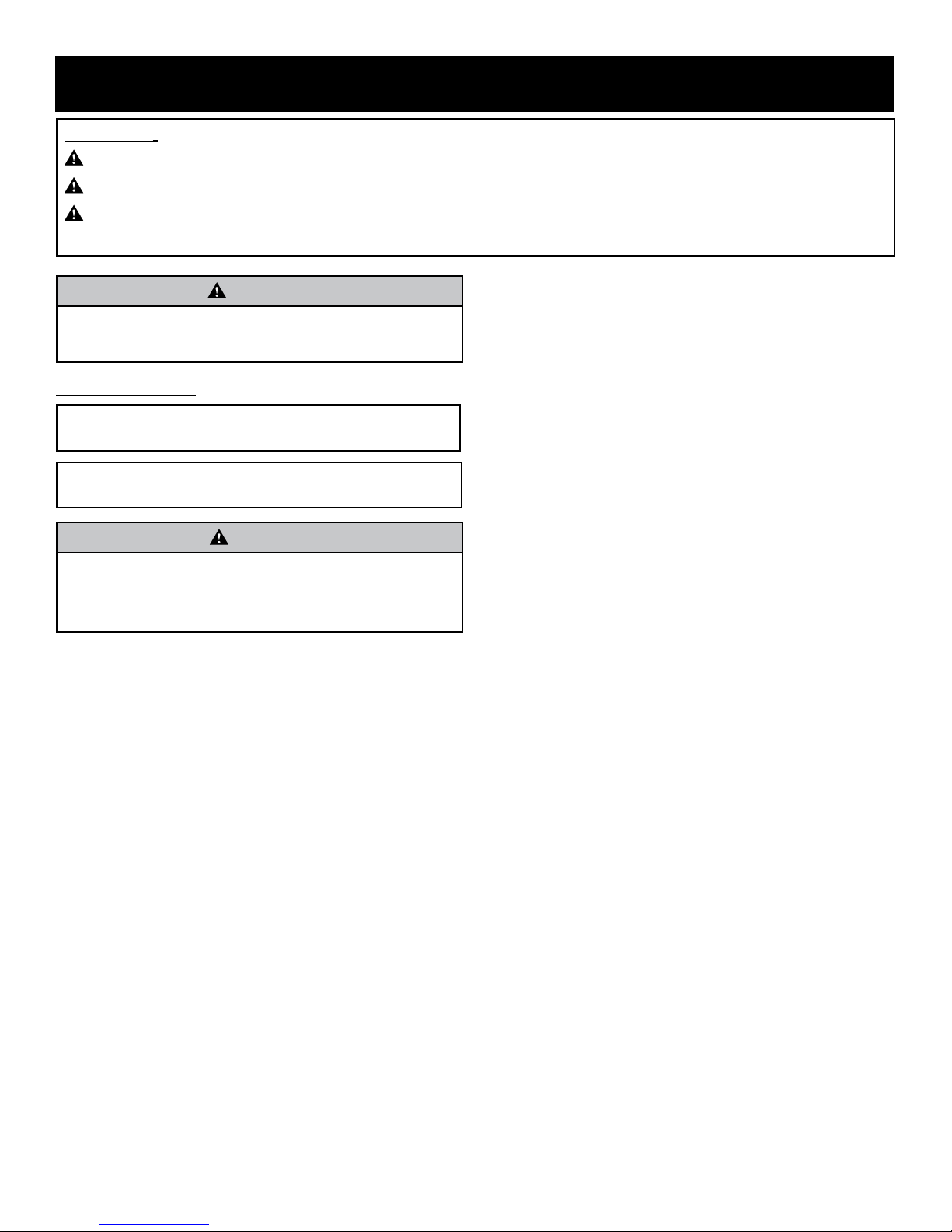
IMPORTANT SAFETY INFORMATION
Denitions:
DANGER: Indicates a hazardous situation which, if not avoided, will result in death or serious injury.
WARNING: Indicates a hazardous situation which, if not avoided, could result in death or serious injury.
CAUTION: Indicates a hazardous situation which, if not avoided, could result in minor or moderate injury.
NOTICE: Addresses practices not related to personal injury.
WARNING
Read and follow these safety precautions prior to operating
this appliance. Failure to follow these precautions may result in
death, injury, or property damage.
Safety Precautions
Before enclosing the vent pipe assembly, operate
the appliance to ensure it is venting properly.
DO NOT OPERATE THIS APPLIANCE WITH-
OUT GLASS FRONT PANEL INSTALLED.
CAUTION
If the glass used in your replace is cracked or damaged in
any way, it should be replaced only with a complete glass
frame assembly from Empire. See parts list on Pages 30
to 31 for ordering.
• Due to high temperatures, the appliance should be located out of trafc and away from furniture and draperies.
• If this appliance is installed directly on carpeting, tile or
other combustible material other than wood ooring the
appliance must be installed on a metal or wood panel
extending the full width and depth of the appliance.
The base referred to above does not mean the reproof
base as used on wood stoves. The protection is for rugs
that are extremely thick and light colored tile.
• Children and adults should be alerted to the hazrds of
high surface temperature and should stay away to avoid
burns or clothing ignition. Alert people – and especially
children – to the hazards of high surface temperatures.
This heater may become hot enough to burn skin and
ignite clothing after prolonged contact. To prevent injury,
caution people to stay clear and avoid touching the heater.
• Young children should be carefully supervised when they
are in the same room as the appliance. Toddlers, young
children, and others may be susceptible to accidental
contract burns. A physical barrier is recommended if there
are at-risk individuals in the house. To restrictr access to
a replace or stove, install an adjustable safety gate to
keep toddlers, young children, and other at-risk individuals
out of the room and away from hot surfaces.
• Always keep the appliance area clear and free from
combustible material, gasoline and other ammable
vapors and liquids.
• This appliance must not share or be connected to a ue
serving a separate solid-fuel burning appliance.
• The vent cap, located on the outside of your home, will
become very hot. Alert everyone, adults and children,
to stay clear and avoid touching the vent cap. Keep the
area around the vent cap clear of combustibles, including shrubs and trees.
• Under no circumstances should any solid fuels (wood,
coal, paper or cardboard etc.) be used in this appliance.
• This appliance requires an unimpeded ow of air to circulate warm air. Do not place objects on or around the
appliance that may restrict air ow to or from the appliance.
• Due to high temperatures, the appliance should be located out of trafc and away from furniture and draper-
ies.
• Keep the area around the heater free of combustible
materials – including drapery, upholstered furniture, paper, boxes, and clothing.
• The glass front or any part removed for servicing the
appliance must be replaced prior to operating the appliance. Work should be done by a qualied service
person.
• Any safety screen, guard, or barrier removed to service
an appliance must be replaced prior to operating the
appliance.
• If the barrier becomes damaged, the barrier shall be
replaced with the manufacturer’s barrier for this appliance.
• Only trim kit(s) supplied by the manufacturer shall be
used in the installation of this appliance.
35657-4-1015 Page 5
IMPORTANT SAFETY INFORMATION
Maintenance Precautions
• Installation and repair should be done by a qualied
service person. The appliance should be inspected
before use and at least annually by a qualied service
person. More frequent cleaning may be required due
to excessive lint from carpeting, bedding material, etc.
It is imperative that control compartments, burners and
circulating air passageways of the appliance be kept
clean.
• Keep burner and control compartment clean.
• Examine venting system periodically and replace damaged parts.
• Make a periodic visual check of pilot and burners. Clean
and replace damaged parts.
Damaged Heater
• Do not use this appliance if any part has been under
water. Immediately call a qualied service technician
to inspect the appliance and to replace any part of the
control system and any gas control which has been under water.
• In the event of a natural disaster (tornado, earthquake,
re, etc.) have a qualied technician inspect the heater
for damage or potential gas leaks. Repair or replace
any damaged components before operating this heater.
• A yearly examination and cleaning of the venting system
of the solid-fuel burning replace must be performed by
a qualied agency.
• Do make a periodic visual check of pilot and burners.
Clean and replace damaged parts.
• Do not use this appliance if any part has been under
water. Immediately call a qualied service technician
to inspect the appliance and to replace any part of the
control system and any gas control which has been under water.
WARNING
Do not operate this gas log set with glass doors closed.
• Clothing or other ammable material should not be
placed on or near the appliance.
• Do not place trash or other articles on the log set during
operation.
• During manufacturing, fabricating and shipping, various
components of this appliance are treated with certain
oils, lms or bonding agents. These bonding agents
are not harmful but may produce annoying smoke and
smells as they are burned off during initial operation of
the appliance. This is a normal temporary occurrence.
A window should be opened during the initial bake out
period.
• Keep burner and control compartment clean.
• Installation and repair should be done by a qualied
service person. The appliance should be inspected
before use and at least annually by a qualied service
person. More frequent cleaning may be required due
to excessive lint from carpeting, bedding materials, hair
from pets, etc. It is imperative that control compartments, burners and circulating air passageways of the
appliance be kept clean.
• Do not put anything around the replace that will obstruct the ow of ventilation air.
• Do keep the appliance area clear and free from combustible material, gasoline and other ammable vapors
and liquids.
35657-4-1015Page 6
SAFETY INFORMATION FOR USERS OF LP-GAS
Propane (LP-Gas) is a ammable gas which can cause res
and explosions. In its natural state, propane is odorless and
colorless. You may not know all the following safety precautions
which can protect both you and your family from an accident.
Read them carefully now, then review them point by point with
the members of your household. Someday when there may not
be a minute to lose, everyone’s safety will depend on knowing
exactly what to do. If, after reading the following information,
you feel you still need more information, please contact your
gas supplier.
LP-GAS WARNING ODOR
If a gas leak happens, you should be able to smell the gas
because of the odorant put in the LP-Gas.
That's your signal to go into immediate action!
• Do not operate electric switches, light matches, use your phone.
Do not do anything that could ignite the gas.
• Get everyone out of the building, vehicle, trailer, or area. Do
that IMMEDIATELY.
• Close all gas tank or cylinder supply valves.
• LP-Gas is heavier than air and may settle in low areas such as
basements. When you have reason to suspect a gas leak, keep
out of basements and other low areas. Stay out until reghters
declare them to be safe.
• Use your neighbor’s phone and call a trained LP-Gas service
person and the re department. Even though you may not
continue to smell gas, do not turn on the gas again. Do not
re-enter the building, vehicle, trailer, or area.
• Finally, let the service man and reghters check for escaped
gas. Have them air out the area before you return. Properly
trained LP-Gas service people should repair the leak, then
check and relight the gas appliance for you.
NO ODOR DETECTED - ODOR FADE
Some people cannot smell well. Some people cannot smell
the odor of the chemical put into the gas. You must nd out if
you can smell the odorant in propane. Smoking can decrease
your ability to smell. Being around an odor for a time can affect your
sensitivity or ability to detect that odor. Sometimes other odors in
the area mask the gas odor. People may not smell the gas odor or
their minds are on something else. Thinking about smelling a gas
odor can make it easier to smell.
The odorant in LP-gas is colorless, and it can fade under some
circumstances. For example, if there is an underground leak, the
movement of the gas through soil can lter the odorant. Odorants in
LP-Gas also are subject to oxidation. This fading can occur if there
is rust inside the storage tank or in iron gas pipes.
The odorant in escaped gas can adsorb or absorb onto or into
walls, masonry and other materials and fabrics in a room. That will
take some of the odorant out of the gas, reducing its odor intensity.
LP-Gas may stratify in a closed area, and the odor intensity could
vary at different levels. Since it is heavier than air, there may be
more odor at lower levels. Always be sensitive to the slightest gas
odor. If you detect any odor, treat it as a serious leak. Immediately
go into action as instructed earlier.
SOME POINTS TO REMEMBER
• Learn to recognize the odor of LP-gas. Your local LP-Gas
Dealer can give you a “Scratch and Sniff” pamphlet. Use it to
nd out what the propane odor smells like. If you suspect that
your LP-Gas has a weak or abnormal odor, call your LP-Gas
Dealer.
• If you are not qualied, do not light pilot lights, perform service,
or make adjustments to appliances on the LP-Gas system. If
you are qualied, consciously think about the odor of LP-Gas
prior to and while lighting pilot lights or performing service or
making adjustments.
• Sometimes a basement or a closed-up house has a musty
smell that can cover up the LP-Gas odor. Do not try to light
pilot lights, perform service, or make adjustments in an area
where the conditions are such that you may not detect the odor
if there has been a leak of LP-Gas.
• Odor fade, due to oxidation by rust or adsorption on walls of
new cylinders and tanks, is possible. Therefore, people should
be particularly alert and careful when new tanks or cylinders
are placed in service. Odor fade can occur in new tanks, or
reinstalled old tanks, if they are lled and allowed to set too
long before relling. Cylinders and tanks which have been out
of service for a time may develop internal rust which will cause
odor fade. If such conditions are suspected to exist, a periodic
sniff test of the gas is advisable. If you have any question
about the gas odor, call your LP-gas dealer. A periodic
sniff test of the LP-gas is a good safety measure under
any condition.
• If, at any time, you do not smell the LP-Gas odorant and you
think you should, assume you have a leak. Then take the same
immediate action recommended above for the occasion when
you do detect the odorized LP-Gas.
• If you experience a complete “gas out,” (the container is under
no vapor pressure), turn the tank valve off immediately. If the
container valve is left on, the container may draw in some air
through openings such as pilot light orices. If this occurs, some
new internal rusting could occur. If the valve is left open, then
treat the container as a new tank. Always be sure your container is under vapor pressure by turning it off at the container
before it goes completely empty or having it relled before it is
completely empty.
35657-4-1015 Page 7
INTRODUCTION
Instructions to Installer
1. Installer must leave instruction manual with owner after
installation.
2. Installer must have owner ll out and mail warranty card supplied
with the replace.
3. Installer should show owner how to start and operate the
replace.
4. Installer must mechanically attach the marking supplied with the
gas replace insert to the inside of the rebox of the replace
into which the gas replace insert is installed.
This direct vent gas replace heater is designed to operate with
all combustion air being siphoned from the outside of the building
and all exhaust gases expelled to the outside of the building. The
information contained in this manual pertains to all models and gas
control systems unless otherwise noted.
WARNING
This unit is not for use with solid fuels
Appliance Certication
This replace is design certied in accordance with American
National Standard/CSA Standard ANSI Z21.88/CSA 2.33 and by
Underwriters Laboratories as a Direct Vent Gas Fireplace Heater
and shall be installed according to these instructions.
Consult your local building code agency, prior to installation, to ensure
compliance with local codes-including permits and inspections.
The replace insert, when installed, must be electrically grounded in
accordance with local codes or, in absence of local codes, with the
National Electric Code ANSI/NFPA 70 or Canadian Electric code,
CSA C22.1, if an external electrical source is utilized.
These models may be installed in a bedroom or bed-sitting room
in the U.S.A. and Canada.
Qualied Installing Agency
Installation and replacement of gas piping, gas utilization equipment
or accessories and repair and servicing of equipment shall be
performed only by a qualied agency. The term “qualied agency”
means any individual, rm, corporation or company which either in
person or through a representative is engaged in and is responsible for
(a) the installation or replacement of gas piping or (b) the connection,
installation, repair or servicing of equipment, who is experienced in
such work, familiar with all precautions required and has complied
with all the requirements of the authority having jurisdiction.
State of Massachusetts: The installation must be made by
a licensed plumber or gas tter in the Commonwealth of
Massachusetts.
The installation must conform with local codes or, in the absence of
local codes, with the National Fuel Gas Code ANSI Z223.1/NFPA
54* Natural Gas and Propane Installation Code, or CSA B149.1 in
Canada. *Available from the American National Standards Institute,
Inc. 11 West 42nd St., New York, N.Y. 10036.
WARNING
ANY CHANGE TO THIS FIREPLACE OR ITS CONTROLS
CAN BE DANGEROUS.
Improper installation or use of the replace can cause
serious injury or death from re, burns, explosions, or
carbon monoxide poisoning
Any alteration of the original design, installed other than as
shown in these instructions or use with a type of gas not
shown on the rating plate is the responsibility of the person
and company making the change.
Important
All correspondence should refer to complete Model Number, Serial
Number and type of gas.
High Altitude
When installing this unit at an elevation above 2000 feet (in the
United States) it may be necessary to decrease the input rating by
changing the existing burner orice to a smaller size. Generally,
input should be reduced 4 percent for each 1000 feet above sea
level. However, if the heating value of the gas has been reduced,
this general rule may not apply. Check with local gas utility for proper
orice size identication.
Canadian High Altitude
Altitude: 0-4500 feet (0-1370 m)
When installing this unit at an elevation above 4500 feet (in Canada),
check with local authorities.
Consult your local gas utility for assistance in determining the proper
orice for location.
Preparation
This direct vent gas replace insert and its components are tested
and safe when installed in accordance with this Installation Manual.
Report to your dealer any parts damaged in shipment, specically
check glass condition. Do not install unit with damaged, incomplete,
or substitute parts. Read all instructions before starting installation
and follow these instructions carefully during installation to insure
maximum benet and safety. Failure to follow them will void your
warranty and may present a re hazard.
The warranty will be voided by, and the warranter disclaims any
responsibility for the following actions:
• Installation of any damaged replace insert or vent system
component.
• Modication of the replace insert or direct vent system.
• Installation other than as instructed by Empire Comfort Systems,
Inc.
• Improper positioning of the logs or glass door assembly.
• Installation and/or use of any component part not manufactured
or approved by manufacturer.
• This appliance comes standard with a 120 VAC cord assembly
to accommodate control options and the blower accessory.
An outlet box may be installed in a bottom back corner of the
existing solid fuel masonry or factory built replace to plug in
the cord assembly, or the supplied power cord may be routed
out onto the hearth to a nearby outlet.
• A 120 VAC circuit fort this product must be protected with
ground-fault circuit-interrupter protection, in compliance with
the applicable electrical codes, when it is installed in locations
such as in bathrooms or near sinks.
• Low voltage and 120 VAC voltage cannot be shared within the
same wall box.
• Once the appliance installation is completed, the installer
should check that control compartment wiring is secured in a
manner as to not interfere with door latches, valve controls, or
the louver assembly.
35657-4-1015Page 8
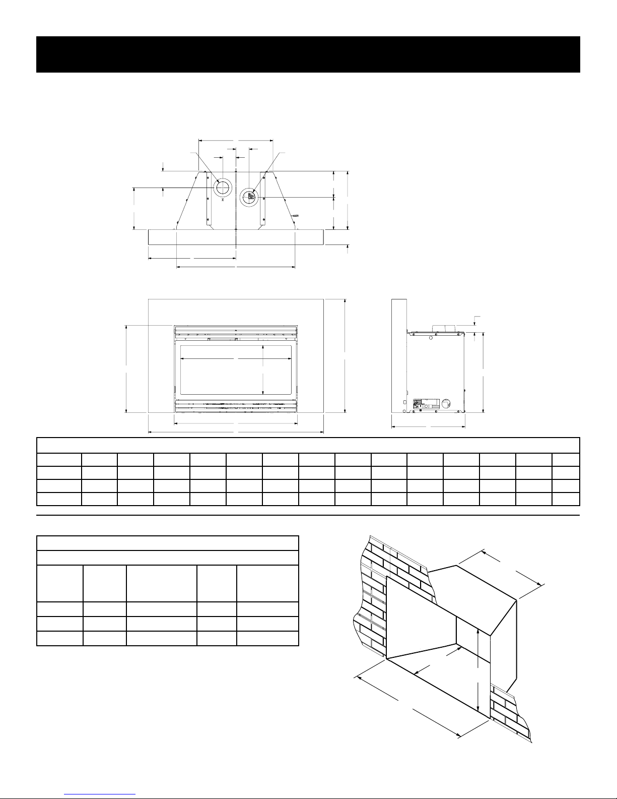
FIREPLACE INSERT DIMENSIONS
N
When planning a replace insert installation, it’s necessary to
determine:
• The vent system conguration to be used.
• Gas supply piping.
G
INTAKE
3" Dia.
3 13/16"
K
L
A
3"
3"
I
E
D
FLUE
3" Dia.
• Whether optional accessories - devices such as a wall switch
or remote control - are desired.
• Electrical supply requirements for blower.
• Proper opening size of replace required for installation of
the replace insert.
6 1/16"
F
J
3 7/16"
1 5/8"
M
H
B
C
Note: 6”, 1-piece
surround shown
DV FIREPLACE INSERT DIMENSIONS
MODEL A B C D E F G H I J K L M N
DV25IN 19-3/4” 28 14-1/2” 11-1/8” 25-1/4” 12-3/4” 17” 18-5/16” 27” 6-3/4” 9” 20” 25-5/8” 40”
DV33IN 22-3/4” 31 16 14-1/8” 28-1/4” 14-1/4” 18-3/4” 21-5/16” 30” 8-1/4” 10-1/2” 21-1/2” 28-5/8” 43”
DV35IN 24-3/4” 34 16 16-1/8” 31-1/4” 14-1/4” 21-3/4” 23-5/16” 33” 8-1/4” 10-1/2” 23” 30-5/8” 46”
Fireplace Opening Dimensional Information/Sizing
MINIMUM FIREPLACE OPENING DIMENSIONS
MODEL
NO.
HEIGHT
A*
FRONT
WIDTH
B
DEPTH
C
REAR
WIDTH
D
D
DV25IN 18-3/8” 27-1/2” 12-3/4” 17-1/4”
DV33IN 21-3/8” 30-1/2” 14-1/4” 19”
DV35IN 23-3/8” 33-1/2” 14-1/4” 22”
*NOTICE: If the replace lintel is wider than 8” (203mm), the
height of the replace opening must be increased a few inches to
allow for a gradual offset in the exhaust and/or intake vent pipes.
C
A
B
35657-4-1015 Page 9
Figure 1
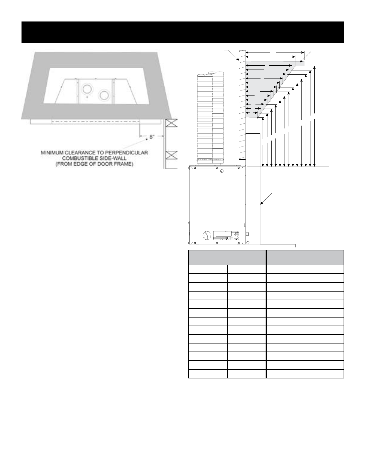
MANTEL AND TRIM CLEARANCES
AREA
FINISHED WALL
Figure 2
O
P
Q
TOP OF INSERT
COMBUSTIBLE
MANTEL/TRIM
N
12”
A
B
C
D
E
F
G
H
I
J
K
L
M
R
S
T
U
V
W
X
Y
Z
SURROUND PANELS
Distance from
Height Above Top of Insert
Face of Fireplace
A 10” N 23”
B 9-1/4” O 22”
C 8-3/4” P 21”
D 8” Q 20”
E 7-1/4” R 19”
F 6-1/2” S 18”
G 6” T 17”
H 5-1/4” U 16”
I 4-1/2” V 15”
J 3-3/4” W 14”
K 3” X 13”
L 2-1/2” Y 12”
M 1-3/4” Z 11”
Figure 3
Combustible Material
No greeting cards, stockings or ornamentation of any type should
be placed on or attached to the replace. The ow of heat can
ignite combustibles.
35657-4-1015Page 10
GAS SUPPLY
GAS SUPPL
CONTROL
If the factory factory built replace has no gas access hole(s) provided,
an access hole of 1.5 in (37.5 mm) or less may be drilled through
the lower sides or bottom of the rebox in a proper workmanship-like
manner. This access hole must be plugged with non-combustible
insulation after the gas supply line has been installed.
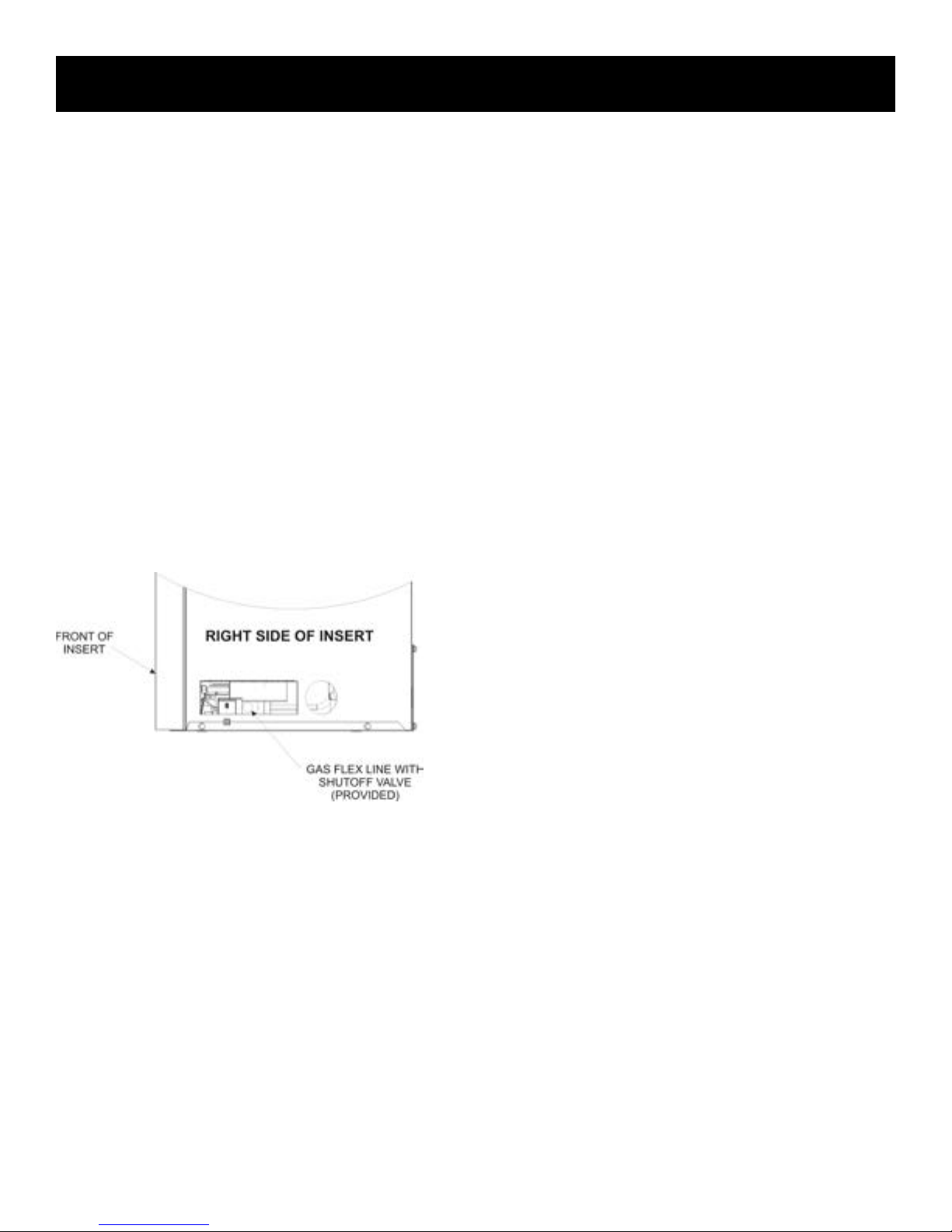
The gas pipeline can be brought in through the right or left side of
the appliance. The insert has a Flexline with shutoff valve located
on the right side when facing the unit. See Figures 4 and 6. Consult
the current National Fuel Gas Code, ANSI Z223.1 CAN/CGA-B149
(.1 or .2) installation code.
Recommended Gas Pipe Diameter
Pipe Length Schedule 40 Pipe
Inside Diameter
Tubing, Type L
Outside Diameter
Nat. L.P. Nat. L.P.
0-10ft
0-3m
11-40ft
4-12m
41-100ft
13-30m
101-150ft
31-46m
1/2"
12.7mm
1/2"
12.7mm
1/2"
12.7mm
3/4"
19mm
3/8"
9.5mm
1/2"
12.7mm
1/2"
12.7mm
1/2"
12.7mm
1/2"
12.7mm
5/8"
15.9mm
3/4"
19mm
7/8"
22.2mm
3/8"
9.5mm
1/2"
12.7mm
1/2"
12.7mm
3/4"
1.9 mm
NOTICE: Never use plastic pipe. Check to conrm whether your
local codes allow copper tubing or galvanized.
NOTICE: Since some municipalities have additional local codes, it
is always best to consult your local authority and installation code.
The use of the following gas connectors is recommended:
— ANS Z21.24 Appliance Connectors of Corrugated Metal Tubing
and Fittings.
— ANS Z21.45 Assembled Flexible Appliance Connectors of Other
Than All-Metal Construction
The above connectors may be used if acceptable by the authority
having jurisdiction. The state of Massachusetts requires that a
exible appliance connector cannot exceed three feet in length.
Gas Supply Pressure (inches w.c.)
Minimum Normal Maximum
Natural Gas 4.5" 7.0" 14.0"
LP (Propane) 10.8" 11.0" 14.0"
Manifold Pressure (inches w.c.)
Normal (HI)
Natural Gas 3.5"
LP (Propane) 10.0"
Installing a New Main Gas Cock
Each appliance should have its own manual gas cock.
A manual main gas cock should be located in the vicinity of the unit.
Where none exists, or where its size or location is not adequate,
contact your local authorized installer for installation or relocation.
Compounds used on threaded joints of gas piping shall be resistant
to the action of liqueed petroleum gases. The gas lines must be
checked for leaks by the installer. This should be done with a soap
solution watching for bubbles on all exposed connections, and if
unexposed, a pressure test should be made.
Never use an exposed ame to check for leaks. Appliance must
be disconnected from piping at inlet of control valve and pipe
capped or plugged for pressure test. Never pressure test with
appliance connected; control valve will sustain damage!
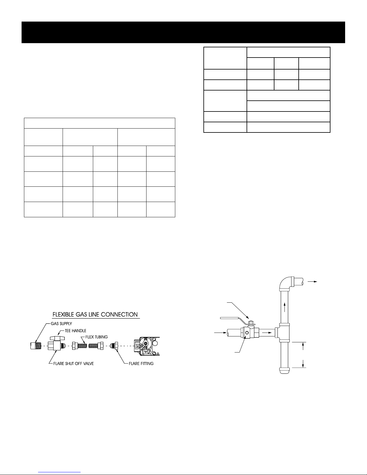
A gas valve and ground joint union should be installed in the gas
line upstream of the gas control to aid in servicing. It is required by
the National Fuel Gas Code that a drip line be installed near the gas
inlet. This should consist of a vertical length of pipe tee connected
into the gas line that is capped on the bottom in which condensation
and foreign particles may collect.
GAS SUPPLY PLUMBING
MANUAL
SHUT-OFF VALVE
TO
VALV E
Figure 4
35657-4-1015 Page 11
Y
INLET
1/8 NPT PLUGGED
HOLE FOR
TEST GAGE
Figure 5
3”
MINIMUM
GAS SUPPLY
NOTICE: The millivolt gas controls are equipped with a captured
screw type pressure test point, therefore it is not necessary to
provide a 1/8” test point up stream of the control.
When using copper or ex connector use only approved ttings.
The appliance and it’s individual shut off valve must be disconnected
from supply piping system during any pressure testing of that system
at test pressures in excess of 1/2 psig (3.5kPa).
The appliance must be isolated from the gas supply piping system
by closing its individual manual shut off valve during any pressure
testing of the gas supply piping system at test pressures equal to
or less than 1/2 psig (3.5kPa).
Attention! If one of the procedures results in pressures in excess of
1/2 psig (14” w.c.) (3.5 kPa) on the replace gas valve, it will result
in a hazardous condition.
Checking Manifold Pressures
Both Propane and Natural gas valves have a built-in pressure
regulator in the gas valve. Natural gas models will have a manifold
pressure of approximately 3.5” w.c. (.871kPa) at the valve outlet
with the inlet pressure to the valve from a minimum of 4.5” w.c.
(1.120kPa) for the purpose of input adjustment to a maximum of
14.0” w.c. (3.484kPa). Propane gas models will have a manifold
pressure approximately 10.0” w.c. (2.49kPa) at the valve outlet
with the inlet pressure to the valve from a minimum of 10.8” w.c.
(2.68kPa) for the purpose of input adjustment to a maximum of
14.0” w.c. (3.484kPa).
Figure 6
35657-4-1015Page 12
VENTING AND INSTALLATION
1. Before beginning, remove glass door and log package from
unit. Also check to make sure there is no hidden damage to
the unit. Take a minute and plan out the gas, venting and elec-
trical route. It is best to start with the gas line rst, followed by
the chimney liner and electrical supply requirements.
2. Minimum replace opening requirements are shown in
Figure 1 of this installation manual. The rebrick (refractory),
glass doors, screen rails, screen mesh and log grates can be
removed from a factory built replace in order to gain mini-
mum gas insert opening requirements prior to installing the
gas replace insert.
3. This insert requires no hearth extensions. Combustible ma-
terial on the oor may be installed up to the insert. Do not
obstruct the lower louver of the insert. The original replace
cannot be returned to solid fuel in this condition.
4. The metal oor of the solid fuel rebox may be removed to
facilitate the installation of the insert. CLEARANCE TO COM-
BUSTIBLE MATERIAL UNDER THE INSERT IS 1/4”. YOU
MUST USE THE LEVELING LEGS TO RAISE THE INSERT
A MINIMUM OF 1/4” IF THE INSERT IS TO SIT ON COM-
BUSTIBLE MATERIAL. The side walls and top structure of the
rebox may not be altered with the exception of removable
bafes and dampers. Smoke shields, shelves and bafes may
be removed if attached with mechanical fasteners. The origi-
nal replace cannot be returned to solid fuel in this condition.
5. The original specied clearances of a factory-built re-
place must be maintained, with the exception of the hearth.
Clearances on a masonry replace must be maintained
at 12” from the opening for combustible projections over
1-1/2”. Clearances for combustible projections under
1-1/2” must be maintained at 6” from the opening per
NFPA211. Plan the surround size accordingly. A surround
must be used with the insert. UNDER NO CIRCUMSTANCE
CAN COMBUSTIBLE MATERIAL BE PLACED BEHIND THE
SURROUND!
6. All manufacturer supplied surrounds, shrouds, and decora-
tive front options have been tested and are approved for use
with the replace insert and may cover existing air circulation
vents or grills on the solid fuel replace it is installed into.
NOTICE: Cutting of sheet metal parts of a replace in order to
install the replace insert is prohibited.
7. To assure top performance, safety and efciency, inserts
must be installed with an approved ue liner as per CAN/CGA
B-149 or National Fuel Code ANSI Z223 and these instructions.
NOTICE: The following statement is also provided on a separate label plate in the instruction packet. Prior to installation
of the replace insert, the installer must mechanically secure
this warning plate to the inside of the replace for future ref-
erence as required.
WARNING
The solid fuel replace has been converted for use with gas
only and cannot be used for burning wood or solid fuels un-
less all original parts have been replaced and the replace
has been reapproved by the authority having jurisdiction.
8. The solid fuel replaces’ ue damper must be fully locked in
the open position or removed for installation of the gas replace insert.
9. The replace and replace chimney must be cleaned and in
good working order and constructed of noncombustible mate-
rials.
10. Make sure that all chimney cleanouts t properly so air cannot
leak into the chimney.
11. Install the insert without the surround panels attached and
make all gas, venting, and electrical connections.
12. To complete the installation, install surround panel assembly.
Please refer to instructions included with the surround panel
kit.
CAUTION
Ensure there are no obstructions to side air passages of
decorative trim once installed on insert.
INSTALLING THE VENT SYSTEM
Vent System Installation Precautions
Before starting installation of vent kits, the installer should read
these instructions and the Vent Kit Instructions to ensure that a
proper vent installation is completed. Consult your local Building
Codes before beginning the Installation.
WARNING
Only surrounds, shrouds, and decorative front components
supplied by the manufacturer may be used to cover integral
grills on the solid-fuel burning replace. No other components such as sheet metal plates may be used to seal off
vents.
35657-4-1015 Page 13
WARNING
THIS GAS INSERT AND VENT ASSEMBLY MUST BE
VENTED DIRECTLY TO THE OUTSIDE AND MUST NEVER BE
ATTACHED TO A CHIMNEY SERVING A SEPARATE SOLID
FUEL BURNING APPLIANCE. EACH GAS APPLIANCE
MUST USE A SEPARATE VENT SYSTEM. COMMON VENT
SYSTEMS ARE PROHIBITED.
VENTING AND INSTALLATION
Vent System Approvals
Figure 8 shows the vent termination caps and systems approved
for use with these models. Approved vent system terminations are
labeled for identication. 3-inch diameter listed exible aluminum
or stainless steel gas vent is used for both the incoming combustion
air and exhaust vent pipes. NO OTHER VENTING SYSTEMS OR
COMPONENTS MAY BE USED. Detailed installation instructions
are included with each vent termination kit and should be used in
conjunction with this manual.
Horizontal Venting
The vent system on this model CANNOT be terminated horizontally.
Vertical Venting
The inlet and exhaust vent pipes MUST be connected to the proper
collars on the unit AND to the termination cap or the unit will not
operate. The intake vent collar is identied by a stamped “I” on the
top collar sliding vent plate assembly.
WARNING
MAJOR U.S. BUILDING CODES SPECIFY MINIMUM
CHIMNEY AND/OR VENT HEIGHT ABOVE THE ROOF TOP.
THESE MINIMUM HEIGHTS ARE NECESSARY IN THE
INTEREST OF SAFETY. SEE FIGURES 8 THROUGH 10 FOR
MINIMUM HEIGHTS, PROVIDED THE TERMINATION CAP IS
AT LEAST 2-FEET FROM A VERTICAL WALL AND 2-FEET
BELOW A HORIZONTAL OVERHANG.
Note: This also pertains to vertical vent systems installed on the
outside of the building.
WARNING
THE EXHAUST PIPE MUST ONLY BE CONNECTED TO THE
EXHAUST STARTING COLLAR OF THE UNIT AND TO THE
EXHAUST COLLAR OF THE TERMINATION CAP.
THE INLET AIR PIPE MUST ONLY BE CONNECTED TO THE
INLET AIR STARTING COLLAR OF THE UNIT AND TO THE
INLET AIR COLLAR OF THE TERMINATION CAP. BOTH THE
INLET VENT AND THE FLUE VENT MUST BE CONNECTED
FROM THE INSERT TO THE VENT TERMINATION CAP.
NOTICE: The minimum vertical vent rise is 10 feet and the
maximum vertical vent rise is 35 feet. These dimensions are
measured from the starting collars of the unit to the end of the last
section of vent pipe. See Figure 8.
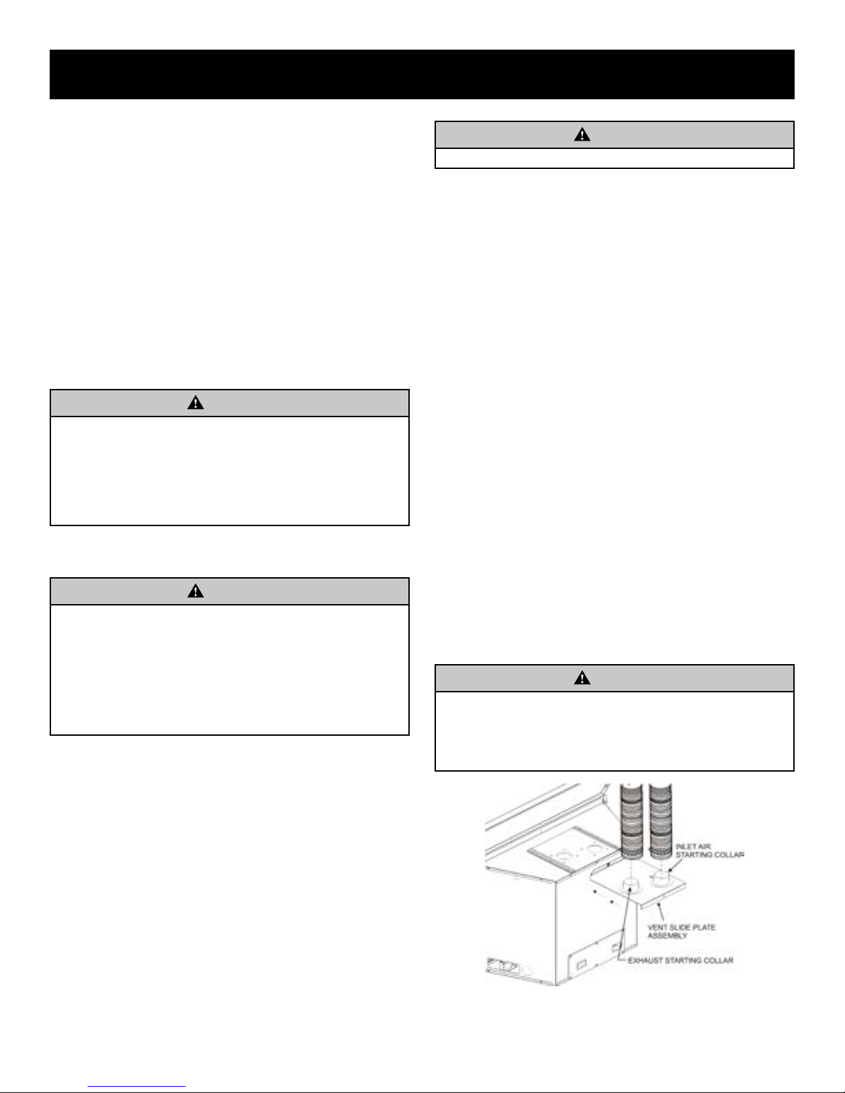
Connecting the Vent Pipe
CAUTION
Sharp edges. Always use gloves when installing.
Install the 3-inch exible vent pipes down through the chimney.
Attach the pipe-to-cap adaptor to the termination cap and the top of
the exible vent pipe, then install the cap to the top of the chimney.
Remove the vent slide plate assembly from the top of the insert.
See Figure 7. Trim off excess venting then attach and secure
the bottom ends of the ex pipes to the starting collars with the
adjustable band clamps provided. Slide the gas insert into place,
and position any excess ex vent pipe back up into the chimney.
Begin installation of the insert into the replace opening. Align
the vent slide plate assembly with the guides located on top of
the insert. Work the insert inch by inch into the replace cavity
as you pull forward on the vent slide plate assembly. Do not use
excessive force on the vent slide plate. Once the vent slide plate is
close to seating, install the black button head 5/16-18 x 2 1/2” long
bolt through the center hole of the insert top ange, and into the
vent slide plate nut. Using the hex key wrench provided, tighten
the bolt until the vent slide plate is seated forward completely.
Positioning, Leveling, and Securing Insert
1. Place the insert into position.
NOTICE: The front anges of the insert (without surround panels)
should be set at approximately 1”(inch) in front of the face of the
replace.
2. Level the insert from side to side and front to back.
3. If necessary, use the leveling bolts included in the instruction
pack. Screw the legs into the nuts installed in the bottom of
the insert. Turn legs in until insert is level.
Note: If desired, it is acceptable to attach metal strapping or
brackets (not provided) from the replace cavity to the insert
outer jacket to secure the Fireplace Insert to the replace
hearth or opening.
CAUTION
TO AVOID DOWNDRAFTS AND/OR COLD AIR PROBLEMS,
IT IS RECOMMENDED TO SEAL OFF THE AREA BETWEEN
THE TERMINATION CAP AND THE TOP OF THE SOLIDFUEL CHIMNEY OPENING INTO WHICH THE VENT CAP
HAS BEEN INSTALLED.
NOTICE: The damper of the masonry chimney may need to be
removed to allow installation of the exible-vent pipe.
When installing into a zero clearance, factory built wood-burning
replace, the use of the DVKI Round Vertical Termination Kit should
allow you to mount the vent adaptor and cap to the exposed round
chimney pipe easily.
Figure 7
35657-4-1015Page 14
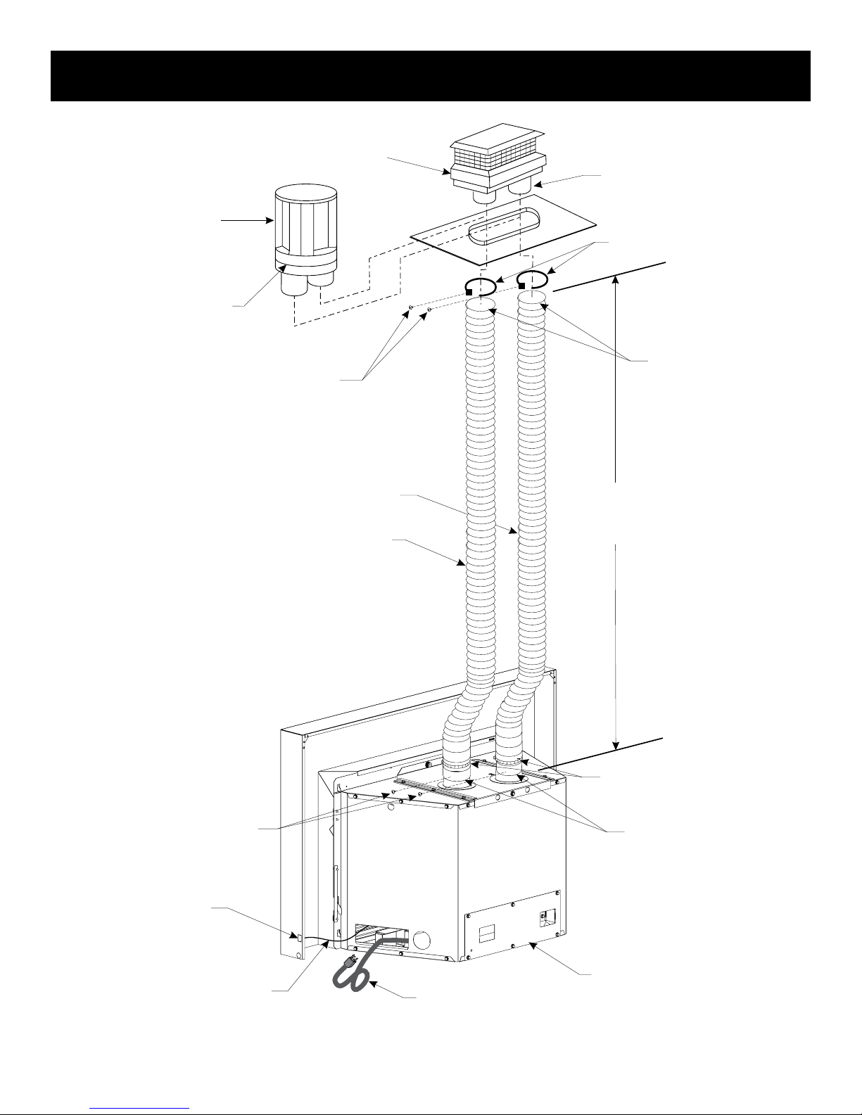
ROUND
TERMINATION CAP
(DVKI KIT)
ROUND CO-LINEAR TO
CO-AXIAL ADAPTOR
VENTING AND INSTALLATION
RECTANGULAR
TERMINATION CAP
(DVVK3FV KIT)
NOTE: LONG EXTENSION
TUBE FOR INLET VENT
CONNECTION
VENT CLAMPS
RETAINER SCREWS MAY
BE INSTALLED THROUGH
THE VENT CLAMPS TO
ENSURE POSITIVE
SECUREMENT OF VENTING
INTAKE VENT
FLUE EXHAUST VENT
USE HIGH TEMP
SEALANT ON VENT
CONNECTIONS
10’ MINIMUM
35’ MAXIMUM
SCREWS ADDED THROUGH
VENT CLAMPS TO RETAIN
VENTING TO COLLARS
RECOMMENDED
OPTIONAL ON/OFF
SWITCH LOCATION
OPTIONAL
LOW VOLTAGE
WIRES
35657-4-1015 Page 15
VENT CLAMPS
USE HIGH TEMP
SEALANT ON VENT
CONNECTIONS
BLOWER ACCESS
COVER PLATE
BLOWER
POWER CORD
Figure 8
 Loading...