

Empire Comfort Systems BVD36FP30LN-2, BVP42FP30FN-2, BVP42FP30LN-2, BVD34FP70FN-1, BVD34FP70LN-1 Installation Instructions And Owner's Manual
...Page 1
INSTALLATION INSTRUCTIONS
AND OWNER'S MANUAL
INSTALLER:
Leave this manual with the appliance.
CONSUMER:
Retain this manual for future reference.
WARNING
FIRE OR EXPLOSION HAZARD
Failure to follow safety warnings exactly
could result in serious injury, death or
property damage.
— Do not store or use gasoline or other
ammable vapors and liquids in the vicinity of this or any other appliance.
— WHAT TO DO IF YOU SMELL GAS
• Do not try to light any appliance.
f i r e - p a r t s . c o m
Do not touch any electrical switch; do
•
not use any phone in your building.
• Leave the building immediately.
• Immediately call your gas supplier
from a neighbor’s phone. Follow the
gas supplier’s instructions.
• If you cannot reach your gas supplier, call the re department.
— Installation and service must be per-
formed by a qualied installer, service
agency or the gas supplier.
B-VENT ZERO CLEARANCE
GAS FIREPLACE
MILLIVOLT MODELS:
BVD34FP30(F,L)N-3
BVD36FP30(F,L)N-2
BVP42FP30(F,L)N-2
IPI ELECTRONIC MODELS:
BVD34FP70(F,L)N-1
BVD36FP70(F,L)N-1
BVP42FP70(F,L)N-1
WARNING
If not installed, operated and maintained in
accordance with the manufacturer’s instructions, this product could expose you to substances in fuel or from fuel combustion which
can cause death or serious illness.
NOT INTENDED FOR USE AS A PRIMARY HEAT
SOURCE. This appliance is tested and approved as
either supplemental room heat or as a decorative
appliance. It should not be factored as primary heat
in residential heating calculations.
This appliance is only for use with the type of gas
indicated on the rating plate. This appliance is not
convertible for use with other gases, unless a certied
kit is used.
UL FILE NO.
MH45034
WARNING
HOT GLASS
CAUSE BURNS.
DO NOT TOUCH
UNTIL COOLED.
NEVER
A barrier designed to reduce the risk of burns from the
hot viewing glass is provided with this appliance and shall
be installed for the protection of children and other at-risk
individuals.
ALLOW CHILDREN
TO TOUCH GLASS.
WILL
GLASS
Page 1
Page 2

TABLE OF CONTENTS
SECTION PAGE
Important Safety Information ...................................................................................................................................... 3
Safety Information for Users of Propane Gas ............................................................................................................. 4
Introduction ................................................................................................................................................................ 5
Specications .............................................................................................................................................................. 6
Fireplace Dimensions ................................................................................................................................................. 6
Clearances .................................................................................................................................................................. 7
Locating Fireplace ...................................................................................................................................................... 7
Gas Supply .............................................................................................................................................................. 8-9
Installation ............................................................................................................................................................10-11
Venting ................................................................................................................................................................. 12-13
Log Placement (BVD34 and BVD36) (5 Log Set) ..................................................................................................... 14
Log Placement (BVP42) (4 Log Set) ........................................................................................................................ 15
Operating Instructions .......................................................................................................................................... 16-17
Standing Pilot Wiring Diagram .................................................................................................................................. 18
Standing Pilot Lighting Instructions ........................................................................................................................... 19
Standing Pilot Troubleshooting ................................................................................................................................. 20
Standing Pilot Propane Gas Conversion ............................................................................................................. 21-22
f i r e - p a r t s . c o m
IPI Electronic System Operating Instructions ........................................................................................................... 23
IPI Electronic System Wiring Diagram ...................................................................................................................... 24
Intermittent Pilot Lighting Instructions ...................................................................................................................... 25
Intermittent Control System Troubleshooting ....................................................................................................... 26-28
Intermittent Pilot Propane Gas Conversion ......................................................................................................... 29-30
Maintenance and Service ......................................................................................................................................... 31
BVD34 Parts List ...................................................................................................................................................... 32
BVD34 Parts View .................................................................................................................................................... 33
BVD36 Parts List ...................................................................................................................................................... 34
BVD36 Parts View .................................................................................................................................................... 35
BVP42 Parts List ....................................................................................................................................................... 36
BVP42 Parts View .................................................................................................................................................... 37
FBB4 Optional Variable Speed Blower Installation .............................................................................................. 38-39
Junction Box Wiring Installation Instructions ............................................................................................................ 40
Barrier Screens ......................................................................................................................................................... 41
Optional Accessories ................................................................................................................................................ 41
Decorative Accessories ............................................................................................................................................ 42
Appliance Service History .................................................................................................................................... 43-44
Master Parts Distributor List ..................................................................................................................................... 45
How To Order Repair Parts ....................................................................................................................................... 45
Quick Reference Guide ....................................................................................................................................... 46-47
Warranty ................................................................................................................................................................... 48
38142-2-0719Page 2
Page 3
IMPORTANT SAFETY INFORMATION
Before enclosing the vent pipe assembly, operate the appliance to ensure it is venting properly.
DO NOT OPERATE THIS APPLIANCE WITHOUT GLASS FRONT PANEL INSTALLED
WARNING
1. “Due to high temperatures, the appliance should be
located out of trafc and away from furniture and
draperies.”
2. “Children and adults should be alerted to the hazards
of high surface temperature and should stay away to
avoid burns or clothing ignition.”
3. “Young children should be carefully supervised when they
are in the same room as the appliance. Toddlers, young
children, and others may be susceptible to accidental
contact burns. A physical barrier is recommended if there
are at-risk individuals in the house. To restrict access to a
replace or stove, install an adjustable safety gate to keep
toddlers, young children, and other at-risk individuals out
of the room and away from hot surfaces.”
4. For appliances requiring a barrier, as determined under
Clause 5.15.4: “A barrier designed to reduce the risk of
burns from the hot viewing glass is provided with this
appliance and shall be installed for the protection of
f i r e - p a r t s . c o m
children and other at-risk individuals.”
5. “If the barrier becomes damaged, the barrier shall
be replaced with the manufacturer’s barrier for this
appliance.
”
6. “Clothing or other ammable material should not be
placed on or near the appliance.”
7. “Any safety screen, guard, or barrier removed for
servicing an appliance must be replaced prior to
operating the appliance” (see Clause 4.1.6).
8. “Installation and repair should be done by a qualied
service person. The appliance should be inspected
before use and at least annually by a professional service
person. More frequent cleaning might be required due to
excessive lint from carpeting, bedding material, et cetera.
It is imperative that control compartments, burners, and
circulating air passageways of the appliance be kept
clean.”
9. The instructions for an appliance optionally for use
with glass doors (or equivalent) shall state that, “Only
doors certied with the appliance shall be used.”
10. The instructions for an appliance not intended for use
with glass doors (or equivalent) shall emphasize that
the appliance is not for use with glass doors.
11. Where applicable, provide a means by which the
consumer can identify the barrier, (such as graphic
representation, clear description, or reference marking).
WARNING
CARBON MONOXIDE POISONING HAZARD
Failure to follow the steps outlined below for each appliance
connected to the venting system being placed into operation
could result in carbon monoxide poisoning or death.
The following steps shall be followed for each appliance
connected to the venting system being placed into operation,
while all other appliances connected to the venting system
are not in operation:
1. Seal any unused openings in the venting system.
2. Inspect the venting system for proper size and horizontal
pitch, as required in the National Fuel Gas Code ANSI
Z223.1/NFPA 54 or the National Gas and Propane
Installation Code CSA B149.1 and these instructions.
Determine that there is no blockage or restriction,
leakage, corrosion and other deciencies which could
cause an unsafe condition.
3. As far as practical, close all building doors and
windows and all doors between the space in which
the appliance(s) connected to the venting system are
located and other spaces of the building.
4. Close replace dampers.
5. Turn on clothes dryers and any appliance not connected
to the venting system. Turn on any exhaust fans, such
as range hoods and bathroom exhausts, so they are
operating at maximum speed. Do not operate a summer
exhaust fan.
6. Follow the lighting instructions. Place the appliance
being inspected into operation. Adjust the thermostat
so appliance is operating continuously.
7. Test for spillage from draft hood equipped appliances
at the draft hood relief opening after 5 minutes of main
burner operation. Use the ame of a match or candle.
8. If improper venting is observed during any of the
above tests, the venting system must be corrected
in accordance with National Fuel Gas Code, ANSI
Z223.1/NFPA and/or National Gas and Propane
Installation Code, CSA B149.1.
9. After it has been determined that each appliance
connected to the venting system properly vents when
tested as outlined above, return doors, windows,
exhaust fans, replace dampers and any other gas-red
burning appliance to their previous conditions of use.
38142-2-0719 Page 3
Page 4

SAFETY INFORMATION FOR USERS OF PROPANE GAS
Propane is a ammable gas which can cause res and explosions.
In its natural state, propane is odorless and colorless. You may
not know all the following safety precautions which can protect
both you and your family from an accident. Read them carefully
now, then review them point by point with the members of your
household. Someday when there may not be a minute to lose,
everyone’s safety will depend on knowing exactly what to do.
If, after reading the following information, you feel you still need
more information, please contact your gas supplier.
PROPANE GAS WARNING ODOR
If a gas leak happens, you should be able to smell the gas
because of the odorant put in the Propane Gas. That's your
signal to go into immediate action!
• Do not operate electric switches, light matches, use your phone.
Do not do anything that could ignite the gas.
• Get everyone out of the building, vehicle, trailer, or area. Do
that IMMEDIATELY.
• Close all gas tank or cylinder supply valves.
• Propane Gas is heavier than air and may settle in low areas
such as basements. When you have reason to suspect a gas
leak, keep out of basements and other low areas. Stay out until
reghters declare them to be safe.
f i r e - p a r t s . c o m
• Use your neighbor’s phone and call a trained Propane Gas
service person and the re department. Even though you may
not continue to smell gas, do not turn on the gas again. Do not
re-enter the building, vehicle, trailer, or area.
• Finally, let the service man and reghters check for escaped
gas. Have them air out the area before you return. Properly
trained Propane Gas service people should repair the leak,
then check and relight the gas appliance for you.
NO ODOR DETECTED - ODOR FADE
Some people cannot smell well. Some people cannot smell
the odor of the chemical put into the gas. You must nd out if
you can smell the odorant in propane. Smoking can decrease
your ability to smell. Being around an odor for a time can affect your
sensitivity or ability to detect that odor. Sometimes other odors in
the area mask the gas odor. People may not smell the gas odor or
their minds are on something else. Thinking about smelling a gas
odor can make it easier to smell.
The odorant in Propane Gas is colorless, and it can fade under
some circumstances. For example, if there is an underground
leak, the movement of the gas through soil can lter the odorant.
Odorants in Propane Gas also are subject to oxidation. This fading
can occur if there is rust inside the storage tank or in iron gas pipes.
The odorant in escaped gas can adsorb or absorb onto or into
walls, masonry and other materials and fabrics in a room. That will
take some of the odorant out of the gas, reducing its odor intensity.
Propane Gas may stratify in a closed area, and the odor intensity
could vary at different levels. Since it is heavier than air, there may
be more odor at lower levels. Always be sensitive to the slightest gas
odor. If you detect any odor, treat it as a serious leak. Immediately
go into action as instructed earlier.
SOME POINTS TO REMEMBER
• Learn to recognize the odor of Propane Gas. Your local Propane
Gas Dealer can give you a “Scratch and Sniff” pamphlet. Use
it to nd out what the propane odor smells like. If you suspect
that your Propane Gas has a weak or abnormal odor, call your
Propane Gas Dealer.
• If you are not qualied, do not light pilot lights, perform service,
or make adjustments to appliances on the Propane Gas system.
If you are qualied, consciously think about the odor of Propane
Gas prior to and while lighting pilot lights or performing service
or making adjustments.
• Sometimes a basement or a closed-up house has a musty
smell that can cover up the Propane Gas odor. Do not try to
light pilot lights, perform service, or make adjustments in an
area where the conditions are such that you may not detect
the odor if there has been a leak of Propane Gas.
• Odor fade, due to oxidation by rust or adsorption on walls of
new cylinders and tanks, is possible. Therefore, people should
be particularly alert and careful when new tanks or cylinders
are placed in service. Odor fade can occur in new tanks, or
reinstalled old tanks, if they are lled and allowed to set too
long before relling. Cylinders and tanks which have been out
of service for a time may develop internal rust which will cause
odor fade. If such conditions are suspected to exist, a periodic
sniff test of the gas is advisable. If you have any question
about the gas odor, call your Propane Gas Dealer. A periodic sniff test of the Propane Gas is a good safety measure
under any condition.
• If, at any time, you do not smell the Propane Gas odorant and
you think you should, assume you have a leak. Then take the
same immediate action recommended above for the occasion
when you do detect the odorized Propane Gas.
• If you experience a complete “gas out,” (the container is under
no vapor pressure), turn the tank valve off immediately. If the
container valve is left on, the container may draw in some air
through openings such as pilot light orices. If this occurs, some
new internal rusting could occur. If the valve is left open, then
treat the container as a new tank. Always be sure your container is under vapor pressure by turning it off at the container
before it goes completely empty or having it relled before it is
completely empty.
38142-2-0719Page 4
Page 5
INTRODUCTION
Instructions to Installer
1. Installer must leave instruction manual with owner after
installation.
2. Installer must have owner ll out and mail warranty card supplied
with the replace.
3. Installer should show owner how to start and operate the replace.
This is a B-Vent gas appliance and must be installed with a listed
B-Vent vent system. The information contained in this manual pertains
to all models and gas control systems unless otherwise noted.
WARNING
This unit is not for use with solid fuels.
Appliance Certication
This replace is design certied in accordance with American
National Standard/CSA Standard ANSI Z.21-50/CSA 2.22 and by
Underwriters Laboratories as a Vented Gas Appliance and shall be
installed according to these instructions.
Consult your local building code agency, prior to installation, to ensure
compliance with local codes-including permits and inspections.
The replace, when installed, must be electrically grounded in
accordance with local codes or, in absence of local codes, with
the National Electric Code ANSI/NFPA 70 if an external electrical
source is utilized.
These models may be installed in a bedroom or bed-sitting room
in the U.S.A.
f i r e - p a r t s . c o m
Qualied Installing Agency
Installation and replacement of gas piping, gas utilization equipment
or accessories and repair and servicing of equipment shall be
performed only by a qualied agency. The term “qualied agency”
means any individual, rm, corporation or company which either in
person or through a representative is engaged in and is responsible for
(a) the installation or replacement of gas piping or (b) the connection,
installation, repair or servicing of equipment, who is experienced in
such work, familiar with all precautions required and has complied
with all the requirements of the authority having jurisdiction.
The installation must conform with local codes or, in the absence of
local codes, with the National Fuel Gas Code ANSI Z223.1/NFPA
54* Natural Gas and Propane Installation Code, or CSA B149.1 in
Canada. *Available from the American National Standards Institute,
Inc. 11 West 42nd St., New York, N.Y. 10036.
Commonwealth of Massachusetts: The installation must be
made by a licensed plumber or gas tter in the Commonwealth
of Massachusetts. The Commonwealth of Massachusetts
requires that a exible appliance connector cannot exceed three
feet in length.
Any alteration of the original design, installed other than as
shown in these instructions or use with a type of gas not
shown on the rating plate is the responsibility of the person
and company making the change.
Important
All correspondence should refer to complete Model Number, Serial
Number and type of gas.
High Altitude
When installing this unit at an elevation above 2000 feet (in the
United States) it may be necessary to decrease the input rating by
changing the existing burner orice to a smaller size. Generally,
input should be reduced 4 percent for each 1000 feet above sea
level. However, if the heating value of the gas has been reduced,
this general rule may not apply. Check with local gas utility for proper
orice size identication.
Canadian High Altitude
Altitude: 0-4500 feet (0-1370 m)
When installing this unit at an elevation above 4500 feet (in Canada),
check with local authorities.
Consult your local gas utility for assistance in determining the proper
orice for location.
Preparation
This gas replace and its components are tested and safe when
installed in accordance with this Installation Manual. Report to your
dealer any parts damaged in shipment, specically check glass
condition. Do not install unit with damaged, incomplete, or substitute
parts. Read all instructions before starting installation and follow
these instructions carefully during installation to insure maximum
benet and safety. Failure to follow them will void your warranty and
may present a re hazard.
The warranty will be voided by, and the warrantor disclaims any
responsibility for the following actions:
• Installation of any damaged replace or vent system component.
• Modication of the replace or vent system.
• Installation other than as instructed by Empire Comfort Systems,
Inc.
• Improper positioning of the logs, glass door, optional accessories
or decorative rock.
• Installation and/or use of any component part not manufactured
or approved by manufacturer.
Glass Specications
Optional glass door kits manufactured with tempered glass
may be installed in hazardous locations such as bathtub
enclosures as dened by the Consumer Product Safety Commission
(CPSC). The tempered glass has been tested and certied to the
requirements of ANSI Z97.1 and CPSC 16 CFR 1202
(Safety Glazing Certication Council SGCC# 1595 and 1597.
Architectural Testing, Inc. Reports 02-31919.01 and
02-31917.01).
This statement is in compliance with CPSC 16 CFR Section
1201.5 "Certication and labeling requirements" which refers
to 15 U.S. Code (USC) 2063 stating "...Such certicate shall
accompany the product or shall otherwise be furnished to any distributor or retailer to whom the product is delivered."
WARNING
ANY CHANGE TO THIS FIREPLACE OR ITS CONTROLS
CAN BE DANGEROUS.
Improper installation or use of the replace can cause
serious injury or death from re, burns, explosions, or
carbon monoxide poisoning.
38142-2-0719 Page 5
Page 6
RIGHT SIDE VIEW
J
H
GAS CONTROLS BEHIND LOWER
LOUVER OR UNDER SLIDING
HEARTH ACCESS DOOR
K
K
L
M
M
G
O
N
P
G
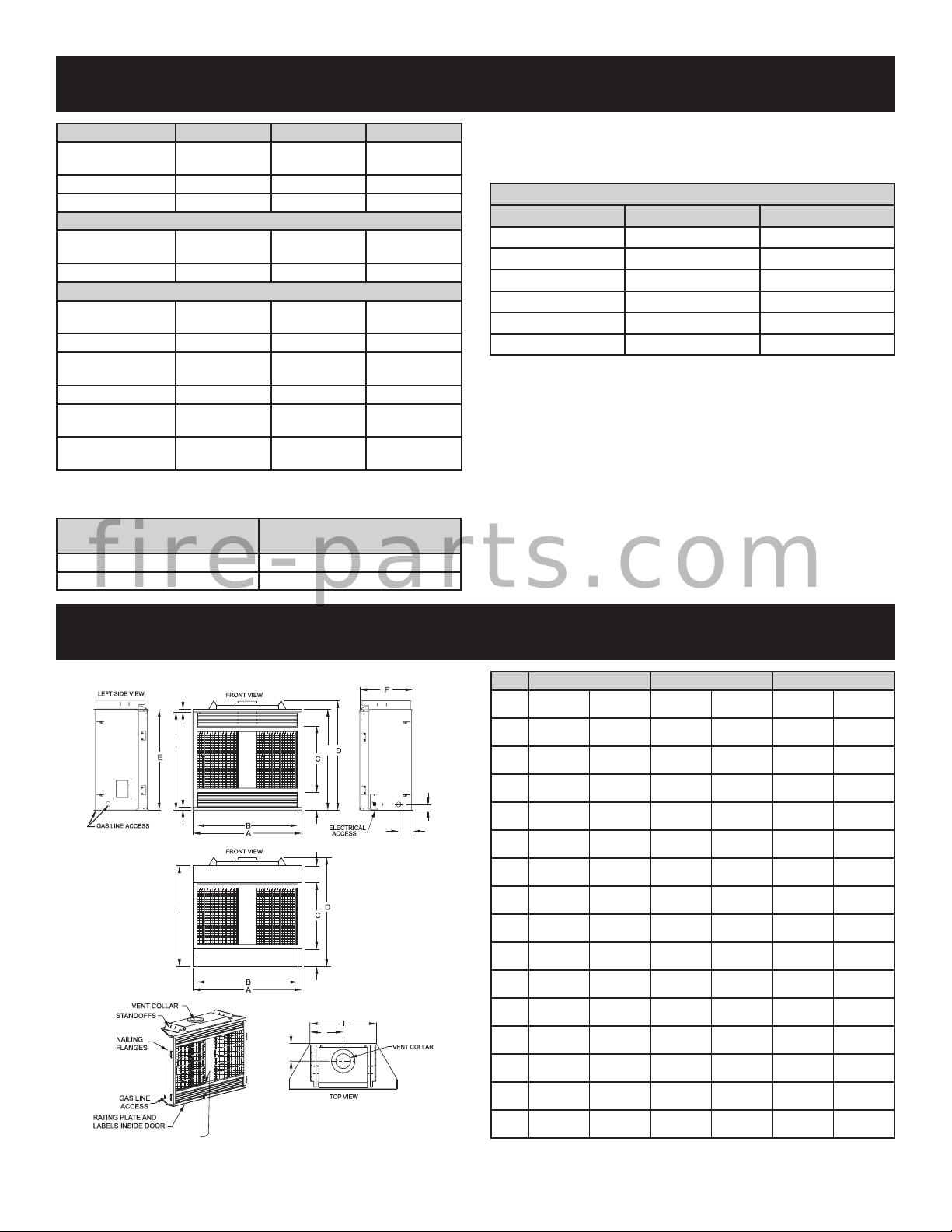
SPECIFICATIONS
BVD34FP BVD36FP BVP42FP
Input Btu/hr
Maximum
KWH (Maximum) 6.2 7.3 8.8
B-Vent Size 4" Diameter 6" Diameter 6" Diameter
Orice
Air Shutter Opening 1/8" (3.2mm) 1/8"(3.2mm) 1/8" (3.2mm)
*PROPANE (CONVERSION KIT REQUIRED)
Orice
Air Shutter Opening 5/16" (7.9mm) 5/16" (7.9mm) Full Open
Height without
standoff
Width 37" (940mm) 39" (990mm) 43" (1,092mm)
Depth
Gas Inlet Shutoff
Valve (Pipe)
*NOTE: Refer to page 21 for millivolt valve conversion kit numbers. Refer
to page 29 for IP valve conversion kit numbers.
REMOTE CONTROL
OPTIONS AND ACCESSORIES
FRBC Millivolt Battery Remote On/Off
f i r e - p a r t s . c o m
FWS-1 Direct Ignition/Millivolt Wall Switch
21,000 25,000 30,000
NATURAL (STANDARD)
#44 (.086)
P-252
1.35mm
P-289
32 3/4"
(832mm)
14 7/8"
(378mm)
1/2 NPT 1/2 NPT 1/2NPT
#42 (.0935)
P-286
1.45 mm
P-208
34 3/4"
(883mm)
18 3/8"
(467mm)
DESCRIPTION
#37 (.104)
P-213
1.65mm
P-250
34 3/4"
(883mm)
18 3/8"
(467mm)
NOTE: Air shutter settings are factory minimum settings. Some
venting congurations may require minor air shutter adjustments
for optimum performance.
GAS CONVERSION KITS
Conversion Kit Conversion Type Used On
BVCK34P Natural To Propane BVD34FP30
BVCK36P Natural To Propane BVD36FP30
BVCK42P Natural To Propane BVP42FP30
38146 Natural To Propane BVD34FP70
38147 Natural To Propane BVD36FP70
38148 Natural To Propane BVP42FP70
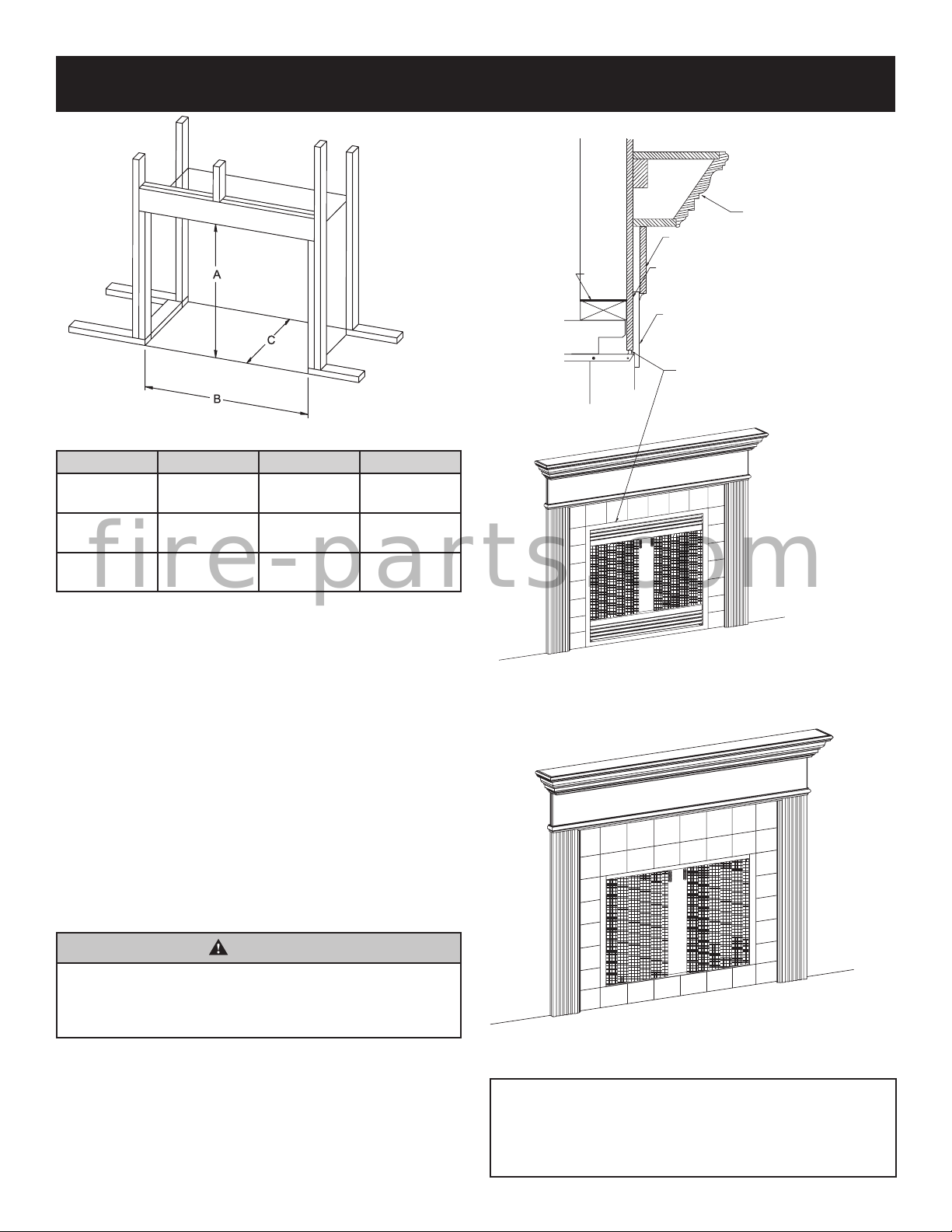
FIREPLACE DIMENSIONS
Dim BVD34 BVD36 BVP42
37" 940mm 39" 990mm 43" 1092mm
A
34" 864mm 36" 914mm 40" 1,016mm
B
22 7/8" 581mm 24 7/8" 632mm 24 7/8" 632mm
C
35 5/8" 905mm 37 5/8" 956mm 37 5/8" 956mm
D
32 3/4" 832mm 34 3/4" 883mm 34 3/4" 883mm
E
14 7/8" 378mm 18 3/8 467mm 18 3/8" 467mm
F
6 3/8" 162mm 6 3/8" 162mm 6 3/8" 162mm
G
5 7/8" 149mm 8 3/8" 213mm 6 3/8" 162mm
H
24 1/2" 622mm 22 1/2" 572mm 26 1/2" 673mm
I
12 1/4" 311mm 11 1/4" 286mm 13 1/4" 337mm
J
1 1/4" 32mm 1 1/4" 32mm 1 1/4" 32mm
K
31 3/4" 807mm 33 3/4" 857mm 33 3/4" 857mm
L
32 11/16" 830mm 34 11/16" 881mm 34 11/16" 881mm
M
2 1/16" 53mm 2 1/16" 53mm 2 1/16" 53mm
N
Figure 1
5 5/8" 143mm 5 5/8" 143mm 5 5/8" 143mm
O
4 7/8" 124mm 4 7/8" 124mm 4 7/8" 124mm
P
38142-2-0719Page 6
Page 7
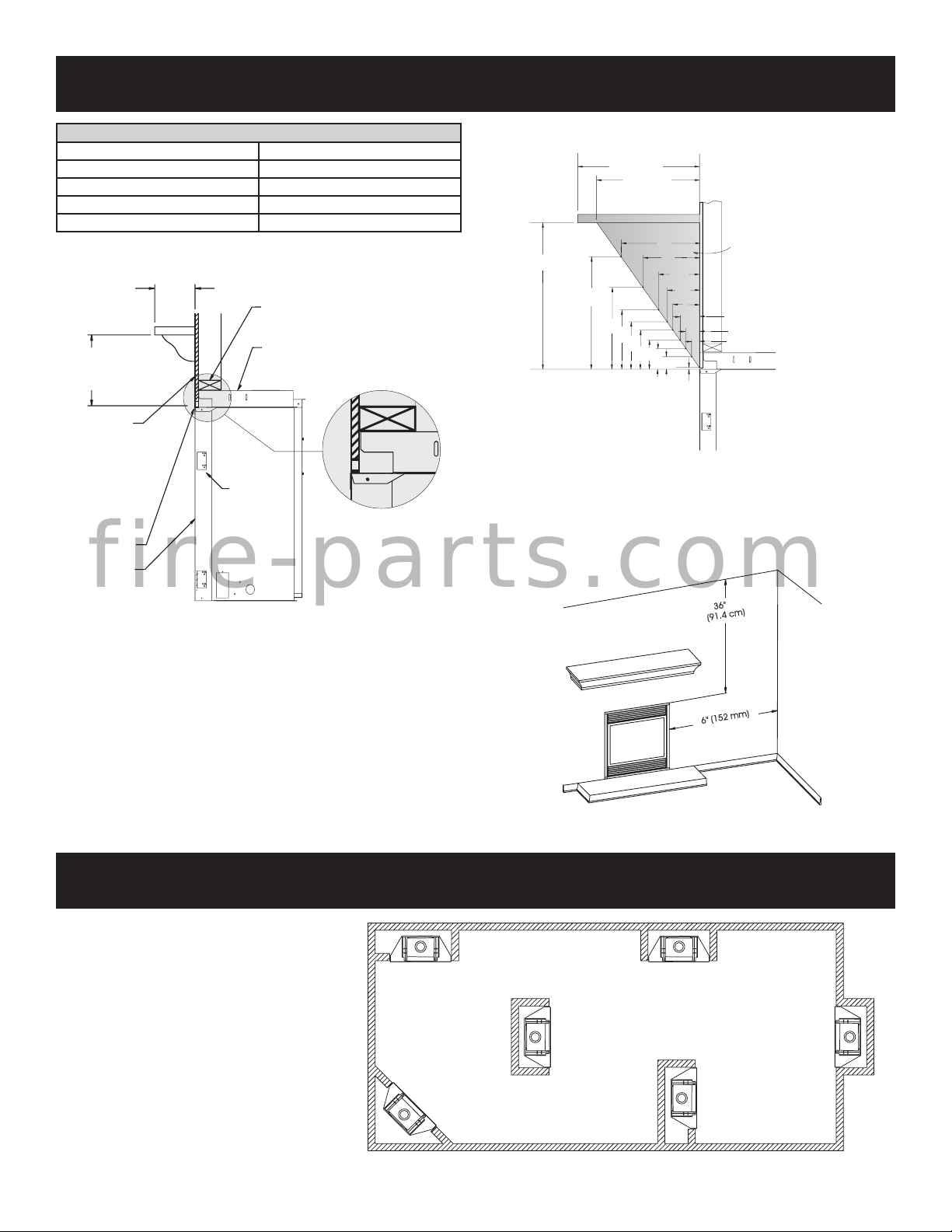
SEE MANTLE CHART FOR
MAXIMUM MANTLE DEPTH
NAILING
FLANGES
GLASS FRONT
(OPTIONAL)
TOP FRAMING
LEDGE
FINISHED WALL
(COMBUSTIBLE)
SEE MANTLE CHART
FOR MINIMUM HEIGHT
OF MANTLE ABOVE UNIT
2"x4" HEADER
STAND OFF
3" (76 mm) HEIGHT
ABOVE TOPOF
FIREPLACE
CLEARANCES
CLEARANCE TO COMBUSTIBLES
Back 0" (0 mm)
Side 0" (0 mm)
Floor 0" (0 mm)
Top Stand-off 0" (0 mm)
Top Framing Edge 1" (25mm)
Mantel Chart (Figure 3)
12”(305mm)
10”(254mm)
MANTEL
COMBUSTIBLE TRIM AND MANTELS
ALLOWED IN SHADED AREA
3”
21/4”
1½”
3/4”
12”
10 3/4”
8”
TOP EDGE OF FIREPLACE
8”
6”
4½”
33/4”
6”
5”
4”
3”
2”
1”
1/4”
(6.35mm)
Figure 3
Clearances (Figure 4)
Clearance from top front edge of replace to ceiling is 36"
Clearance from side of replace to adjacent sidewall is 6".
f i r e - p a r t s . c o m
Combustible Material
No greeting cards, stockings or ornamentation of any type
should be placed on or attached to the replace. The ow of
heat can ignite combustibles.
NOTE: When you install your Fireplace on
wall corner positions, a minimum of 6 inches
clearance must be maintained from the
perpendicular side wall and the screened
opening of the appliance.
Figure 2
Figure 4
LOCATING FIREPLACE
38142-2-0719 Page 7
Figure 5
Page 8
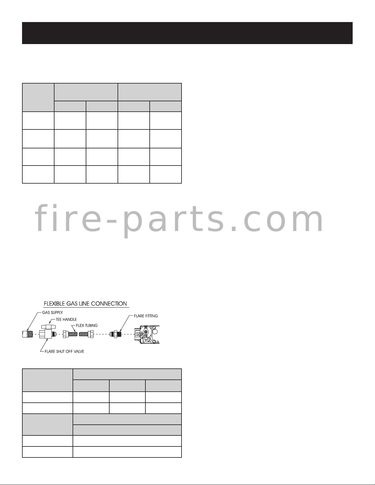
GAS SUPPLY
The gas pipeline can be brought in through the right or left
side of the appliance. Consult the current National Fuel Gas
Code, ANSI Z223.1 CAN/CGA-B149 (.1 or .2) installation code.
RECOMMENDED GAS PIPE DIAMETER
Pipe
Length
(Feet)
0-10
11-40
41-100
101-150
NOTE: Never use plastic pipe. Check to conrm whether your
local codes allow copper tubing or galvanized.
NOTE: Since some municipalities have additional local
codes, it is always best to consult your local authority and
installation code.
f i r e - p a r t s . c o m
The use of the following gas connectors is recommended:
—ANSI Z21.24 Appliance Connectors of Corrugated Metal
Tubing and Fittings.
—ANSI Z21.45 Assembled Flexible Appliance Connectors
of Other Than All-Metal Construction
The above connectors may be used if acceptable by
the authority having jurisdiction. The Commonwealth of
Massachusetts requires that a exible appliance connector
cannot exceed three feet in length.
Schedule 40 Pipe
Inside Diameter
NaturaL Propane Natural Propane
1/2"
12.7mm
1/2"
12.7mm
1/2"
12.7mm
3/4"
19mm
3/8"
9.5mm
1/2"
12.7mm
1/2"
12.7mm
1/2"
12.7mm
Tubing, Type L
Outside Diameter
1/2"
12.7mm
5/8"
15.9mm
3/4"
19mm
7/8"
22.2mm
3/8"
9.5mm
1/2"
12.7mm
1/2"
12.7mm
3/4"
1.9 mm
Installing a New Main Gas Shut-Off
Each appliance should have its own manual gas shut-off.
A manual main gas shut-off should be located in the vicinity of
the unit. Where none exists, or where its size or location is not
adequate, contact your local authorized installer for installation or relocation.
Compounds used on threaded joints of gas piping shall be
resistant to the action of liqueed petroleum gases. The gas
lines must be checked for leaks by the installer. This should
be done with a soap solution watching for bubbles on all
exposed connections, and if unexposed, a pressure test
should be made.
Never use an exposed ame to check for leaks. Appliance
must be disconnected from piping at inlet of control valve
and pipe capped or plugged for pressure test. Never
pressure test with appliance connected; control valve
will sustain damage!
NOTE: The millivolt gas controls are equipped with a captured
screw type pressure test point, therefore it is not necessary
to provide a 1/8" test point up stream of the control.
On direct ignition valves, hex plugs may be replaced with
hose ttings for pressure checks, then reinstalled before
operating replace.
When using copper or ex connector use only approved
ttings
.
The appliance and it’s individual shut off valve must be
disconnected from supply piping system during any pressure
testing of that system at test pressures in excess of 1/2 psig
(3.5kPa).
The appliance must be isolated from the gas supply piping
system by closing its individual manual shut off valve during
any pressure testing of the gas supply piping system at test
pressures equal to or less than 1/2 psig (3.5kPa).
Attention! If one of the procedures results in pressures in
excess of 1/2 psig (14" w.c.) (3.5 kPa) on the replace gas
valve, it will result in a hazardous condition.
Figure 6
Gas Supply Pressure (inches w.c.)
Minimum Normal Maximum
Natural Gas 4.5" 7.0" 14.0"
Propane Gas 10.8" 11.0" 14.0"
Manifold Pressure (inches w.c.)
Normal (HI)
Natural Gas 3.5"
Propane Gas 10.0"
38142-2-0719Page 8
Page 9
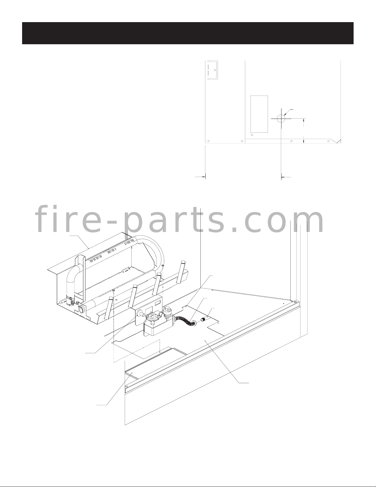
BURNER
GAS SUPPLY (CONT'D)
Checking Manifold Pressures
Both Propane and Natural Gas valves have a built-in pressure
regulator in the gas valve. Natural Gas models will have a
manifold pressure of approximately 3.5" w.c. (.871kPa) at
the valve outlet with the inlet pressure to the valve from a
minimum of 4.5" w.c. (1.120kPa) for the purpose of input
adjustment to a maximum of 14.0" w.c. (3.484kPa). Propane
Gas models will have a manifold pressure approximately 10.0"
w.c. (2.49kPa) at the valve outlet with the inlet pressure to the
valve from a minimum of 10.8" w.c. (2.68kPa) for the purpose
of input adjustment to a maximum of 14.0" w.c. (3.484kPa).
GAS LINE HOLE
3½”
FROM FRONT OF
APPLIANCE TO
GAS LINE HOLE
BVD34 SERIES-10”
BVD,P (36,42)-13½”
Figure 7
f i r e - p a r t s . c o m
ASSEMBLY
REAR TA B (BURNER BASE)
LOCATIONS
FLEXIBLE GAS CONNECTOR
GAS SUPPLY LINE
PIEZO
IGNITER
FIREBOX BOTTOM
CUTOUT ACCESS
SLIDING
VALV E ACCESS
COVER
Figure 8
38142-2-0719 Page 9
Page 10
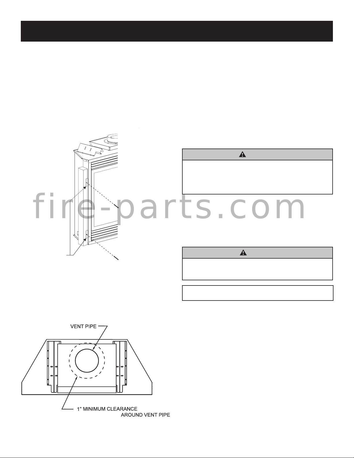
INSTALLATION
NAILOR OTHER SUITABLE FASTENER
MOUNTING
BRACKETS
B-
TO
COMBUSTIBLES
Framing and Finishing
1. Choose unit location.
2. Frame in replace with a header across the top. It is
important to allow for the nished face thickness when
setting the depth of the frame. See Figures 9 & 11.
3. Attach replace to framing using (4) adjustable nailing
anges. Preset depth to suit facing material (adjustable
to 1/2", 5/8" or 3/4" depths).
4. Use (8) 1/2" hex-head screws supplied in hardware
package to screw through slotted holes in nailing anges,
then screw into pre-drilled holes on replace side. Measure
from face of replace to face of the nailing anges to
determine nal depth.
f i r e - p a r t s . c o m
Install the Fresh Air Kit - BVA1
A fresh air kit is available as an optional feature with this
appliance. The fresh air kit helps to decrease the amount
of room air taken by utilizing outside air for combustion. It is
strongly recommended that it be installed. Installation of the
fresh air kit should be performed at the framing stage of the
replace installation.
The fresh air kit installs on the left side of the replace.
To install the BVA1 fresh air kit, refer to the installation
instructions provided with the kit.
NOTE: The outside air kit can terminate at any level with
the exception that it must terminate at least 1 ft below the
vent termination cap. The fresh air kit inlet hood should be
positioned at least 2 ft above the ground level, in a manner
that will not allow snow, leaves, etc. to block the inlet.
WARNING
Exhaust products of gasoline engines are hazardous.
The outside air must not be taken from a garage
space, attic spaces, basements, or above the roong
where other heating appliance, fans, or chimneys
exhaust or utilize the air.
Framing (Figure 11)
Fireplace framing can be built before or after the replace is
set in place. Framing should be positioned to accommodate
wall covering and replace facing material. The replace
framing should be constructed of 2 x 4 lumber or heavier. The
framing headers may rest on the replace standoffs. Refer
to Figure 11 for minimum framing dimensions.
Figure 9
Vent Pipe Clearance
NOTE: Maintain one inch (1") of clearance around vertical
vent pipe. Follow the B-Vent system instructions for installation
requirements and clearances. Failure to follow the B-Vent
manufacturer's instructions may cause improper draft and
possible re hazard.
CAUTION
Measure replace dimensions and verify framing
methods, and wall covering details before framing
construction begins
Framing dimension "A" includes a three inch
clearance for standoffs on rebox.
Figure 10
38142-2-0719Page 10
Page 11
INSTALLATION (CONT'D)
FINISHED WALL
JOINT BETWEEN FINISHED WALLAND
UNIT SEALED WITH 300°F149
MATERIAL (SEALANT IS OPTIONAL)
°C
SEALANT
COMBUSTIBLE SURROUND
MANTELSHELF
2X4
HEADER
STAND OFF
FRONT TRIM OR NON-COMBUSTIBLE
MATERIAL MAY OVERLAP BLACK PAINTED
FACE (INSTALLATION IS OPTIONAL)
Combustible Surround Installation
Minimum Framing Dimensions
BVD34 BVD36 BVP42
"A"
"B"
"C"
f i r e - p a r t s . c o m
35 3/4"
(908mm)
37 3/8"
(949mm)
14 3/8"
(378mm)
37 3/4"
(959mm)
39 3/8"
(1,000mm)
17 7/8"
(454mm)
37 3/4"
(959mm)
43 3/8"
(1,102mm)
17 7/8"
(454mm)
NOTE: Dimension "C" is the minimum with the replace face extending 1/2"
in front of the framing to allow for nishing materials.
Figure 11
Attention: Add 3-3/4" to “A” dimensions when using a ush
mantel base.
Attention: If a base or mantel is not used and the appliance
is installed directly on carpeting, tile or other combustible
material other than wood ooring, it shall be installed on a
metal or wood panel extending the full width and depth of
the appliance. The vertical dimension in Figure 11 must be
adjusted when a metal or wood panel is placed beneath the
appliance.
Finishing (Figure 12)
Finish the walls with the material of your choice. Only
non-combustible materials may be used to cover the black
replace front.
WARNING
When nishing the replace never obstruct or modify
the air inlet/outlet louvers in any manner. Provide
adequate clearances around air openings into the
combustion chamber.
Caution: If the joints between the nished wall and the re-
place surround (top and sides) are sealed, a 300°F minimum
sealant material must be used. These joints are not required
to be sealed. Only non-combustible material (using 300°F
minimum adhesive if needed), can be applied as facing to
the replace surround.
Louvered Models
Figure 12a
Flush Face Models
Figure 12b
Attention: Cold climate installation recommendation:
When installing this unit against a non-insulated
exterior wall, it is recommended that the outer walls
be insulated to conform to applicable insulation
codes.
38142-2-0719 Page 11
Page 12
LOWEST
VENTING
Vent Runs
In planning the installation for the replace, it is necessary to
install certain components before the appliance is completely
positioned and installed. These include the vent system, gas
piping for the appliance, Fresh Air Kit, and the electrical wiring.
(The fan option is available for louvered models only. Electric
ignition models will require electrical service to junction box).
The appliance can be mounted on any of the following surfaces:
1. A at, hard combustible (burnable) surface.
2. A raised wooden platform.
3. Four (4) corner supports. (Example: Four (4) concrete
masonry blocks.) These supports must be positioned so
they contact all four (4) perimeter edges on the bottom
of the unit.
Locate and mark the center point of the vent pipe using a
nail on the underside of the roof. Drive the nail through the
center point. Mark the outline of the roof hole around this
center point.
NOTE: Size of the roof hole dimensions depend on the pitch
of the roof. There must be a 1 inch clearance (25mm)
to the vertical pipe sections. This clearance is to all
combustible material.
Cover the opening of the vent pipe and cut and frame the roof
hole. Use framing lumber the same size as the roof rafters
f i r e - p a r t s . c o m
and install the frame securely. Flashing anchored to frame
must withstand high winds. The storm collar is placed over
this joint to make a water-tight seal. Non-hardening sealant
should be used to completely seal this ashing installation.
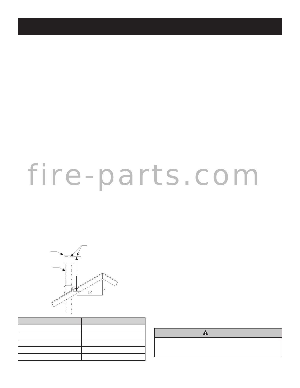
Determining Minimum Vent Height Above the Roof.
WARNING: Major U.S. building codes specify minimum
chimney and/or vent height above the roof top. These
minimum heights are necessary in the interest of safety.
These specications are summarized in Figures 14 and 15.
DISCHARGE
VENT CAP
GAS VENT
ROOF PITCH H (Min.)
Flat to 6/12 12" (305 mm)
6/12 to 7/12 15" (381 mm)
Over 7/12 to 8/12 18" (457 mm)
Over 8/12 to 16/12 24" (610 mm)
Over 16/12 to 21/12 36" (914 mm)
OPENING
H
ROOF PITCH IS X/12
H (Min.)-Minimum height from
roof to lowest discharge opening
Note that for steep roof pitches, the vent height must be
increased. In high wind conditions, nearby trees, adjoining
roof lines, steep pitched roofs, and other similar factors can
result in poor draft, or down-drafting. In these cases, increasing
the vent height may solve this problem.
General Maintenance
Conduct an inspection of the venting system semi-annually.
Recommended areas to inspect are as follows:
1. Check areas of the venting system which are exposed
to the elements for corrosion. These will appear as rust
spots or streaks and, in extreme cases, holes. These
components should immediately be replaced.
2. Remove the cap and shine a ashlight down the vent.
Remove any bird nests or other foreign material.
3. Check for evidence of excessive condensate, such as
water droplets forming in the inner liner and subsequently
dripping out at joints. Condensate can cause corrosion
of caps, pipe and ttings. It may be caused by having
excessive lateral runs, too many elbows and exterior
portions of the system being exposed to cold weather.
4. Inspect joints to verify that no pipe sections or ttings have
been disturbed and, consequently, loosened. Also, check
mechanical supports, such as wall straps or plumbers’
tape for rigidity.
A removable panel or other means must be provided in the
enclosure for visual inspection of the ue connection.
NOTE: This also pertains to vertical vent systems installed
on the outside of the building.
Installing the Vent System in a Chase
A chase is a vertical box-like structure built to enclose the
gas appliance and/or it’s vent system. Vertical vent runs on
the outside of a building may be, but are not required to be
installed inside a chase.
CAUTION: Treatment of restop spacers and construction
of the chase may vary with the type of building. These
instructions are not substitutes for the requirements
of local building codes. Therefore, your local building
codes must be checked to determine the requirements
for these steps.
NOTE: When installing this vent system in a chase, it is always
good building practice to insulate the chase as you would the
outside walls of your home. This is especially important for cold
climate installations. Upon completion of building your chase
framing, install the vent system by following the instructions in
this manual. Remember to build the chase large enough so
that minimum clearance of combustible materials (including
insulation) to the vent system are maintained.
WARNING
This appliance must not be connected to a chimney
ue servicing a separate solid fuel or gas fuel burning
appliance.
Figure 13
38142-2-0719Page 12
Page 13
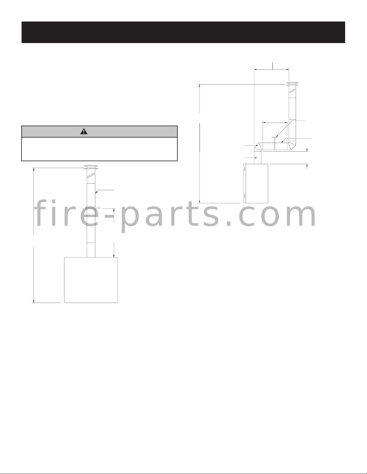
40
11
90-degree or
45-degree Elbows
Straight Section
2 ft. Minimum offtop of
unit before using elbows
Vent supports per
manufacturers vent
specifications
Horizontalvent
to maintaina1/4”
rise per ft. Min.
11 ft. Min.
Maximum horizontal
distanceis 50% of
vertical ventheight
5 ft. Max.
Horizontal at
11 ft. Min.
Vertical
VENTING (CONT'D)
Vent Size
Model BVD34FP series uses a 4" B-Vent for operation.
Models BVD36FP and BVP42FP series use a 6" B-Vent for
operation.
Never downsize venting diameters.
Clearances
Vent clearances are per vent manufacturer's specications
Vent Conguration
Various venting congurations are shown in Figures 14 and
15 from which maximum vent runs can be determined.
WARNING
Always maintain minimum clearances or greater
around the vent system. Do not pack air spaces with
insulation or other material.
Minimum clearances are
per vent manufacturer’s
specifications
f i r e - p a r t s . c o m
ft. Max.
ft. Min.
Vertical Venting - No Elbows
Vent supports are per
vent manufacturer’s
specifications
Figure 14
Offset Venting - With Elbows
Figure 15
38142-2-0719 Page 13
Page 14
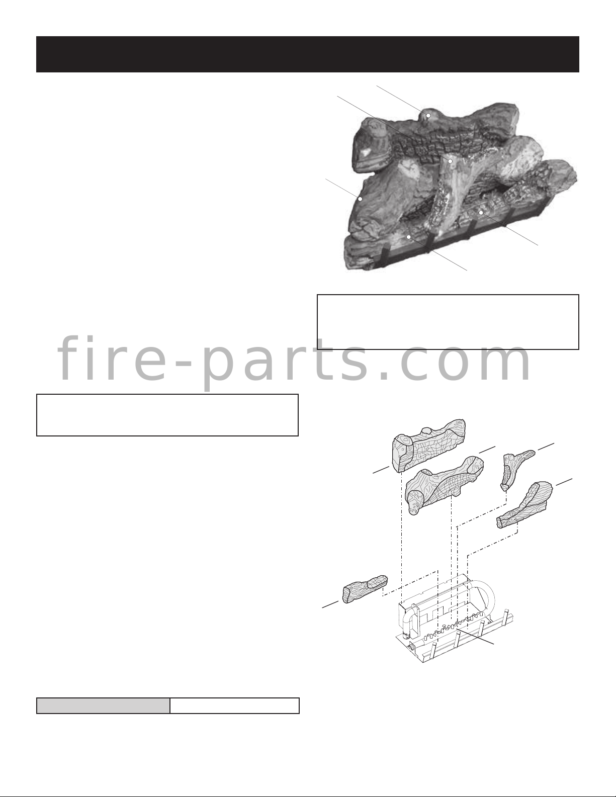
3
1
2
LOG PLACEMENT (5 LOG SET)
Before you begin: if you are installing logs into the BVD34
or BVD36 model, then this replace is supplied with a set of
ve ceramic ber logs. Do not handle these logs with your
bare hands! Always wear gloves to prevent skin irritation from
ceramic bers. After handling logs, wash your hands gently
with soap and water to remove any traces of bers.
The positioning of the logs is critical to the safe and clean
operation of this replace. Sooting and other problems may
result if the logs are not properly and rmly positioned in
the replace. Please refer to Figure 16 and Figure 17 and
corresponding WARNING when completing following log
placement instructions.
1. Place front logs (#1 and #2) between front grate ange
and main burner. Align notches on front logs with locator
tabs in base.
2. Place middle log (#3) between front and rear loop of
burner.
Note: Do not place log on top of pilot assembly.
3. Place rear log (#4) on rear log shelf. Bottom ange of log
must be placed between the log shelf and burner tube.
4. Place branch (#5) onto (#1) log and at area on (#3) log.
The bottom of the branch is to be placed behind the grate
tang that is second from the left.
5. Place decorative rock in front of grates and sides of main
f i r e - p a r t s . c o m
burner pan.
ATTENTION: Do not place decorative rock on logs or
burner. The decorative rock should only be placed on the
replace oor.
EMBER MATERIAL PLACEMENT ON BURNER
5
WARNING: Failure to position the parts in accordance
with this diagram or failure to use only parts
specically approved with this appliance may result
in property damage or personal injury.
Attention: Do not use Figure 16 or Figure 17 to order
logs. Refer to parts list on pages 32 and 34 and parts view
on pages 33 and 35 to order logs and/or ember material for
your appropriate replace model.
4
1
Figure 16
2
3
5
6. After all logs are positioned properly, apply Rockwool
ember material to the front burner port area. To apply,
carefully separate the ember material into small amounts
no larger than "dime size" pieces. Fluffed up pieces one
layer thick on top of the burner generally works best, and
will provide the best ember glow. Do not place ember
material more than one layer thick. No more than (1)
small packet of ember material (part no. 15999) evenly
placed on the burner, is recommended on BVD34 and
BVD36 models. Using additional ember material will
decrease the amount of ember glow effect. Extra ember
material should be saved for future ember applications
as necessary. See Figure 17.
Optional Platinum Bright Ember Kits are available from your
Fireplace Dealer. These embers may be used with all BVD/
BVP Series replaces. Order and use as indicated as below.
Platinum Bright Embers PE-20-1
Note: A signle layer of embers is to be used when applying
Platinum Bright Embers (alone or in combination with
production embers) to the burner.
4
EMBER MATERIAL
PLACEMENT
Figure 17
38142-2-0719Page 14
Page 15
REAR LOG
LOCATOR PINS
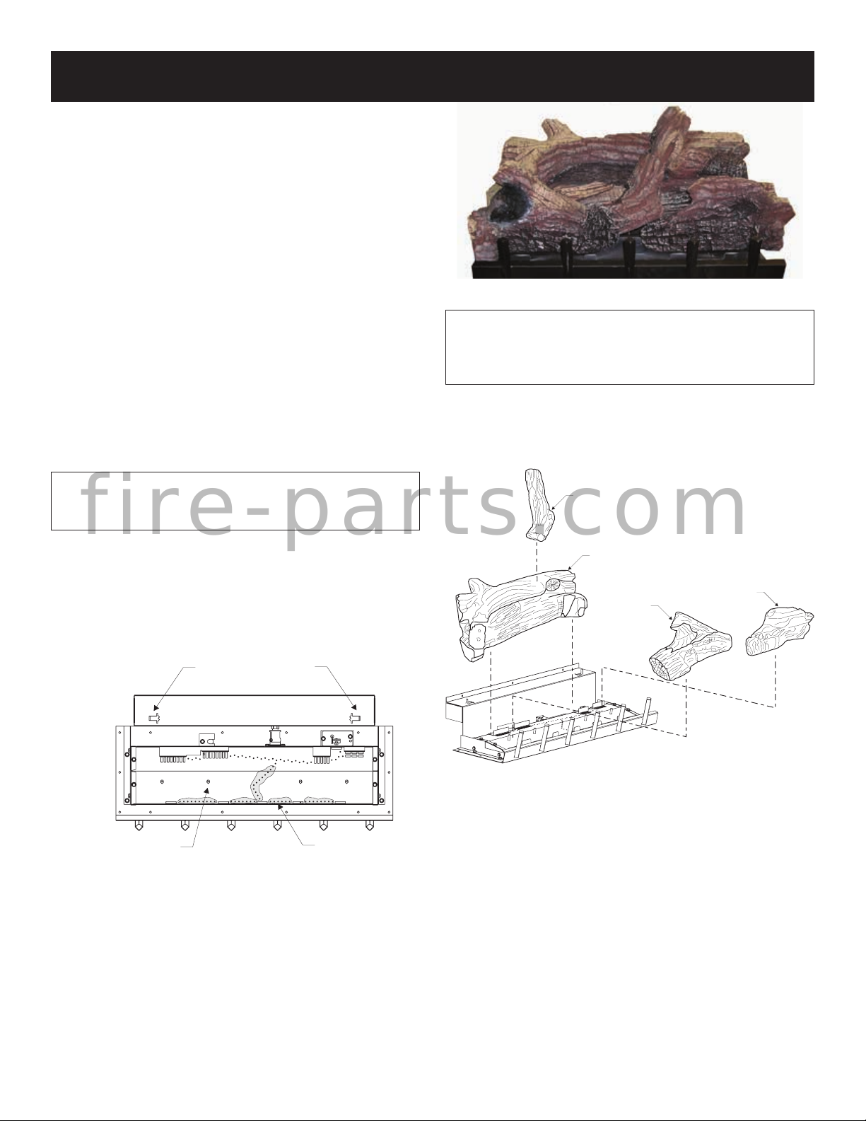
LOG PLACEMENT (4 LOG SET)
Before you begin: This replace is supplied with a set of
four ceramic ber logs. Do not handle these logs with your
bare hands. Always wear gloves to prevent skin irritation
from ceramic bers. After handling logs, wash your hands
gently with soap and water to remove any traces of ber.
The positioning of logs is critical to safe and clean operation
of this replace. Sooting and other problems may result
if the logs are not properly and rmly positioned in the
replace. Please refer to Figure 18, Figure 19, and Figure
20 and corresponding WARNING, when completing the
following log placement steps.
1. Place rear (#1) log onto two (2) pins on rear log support.
2. Place left, front (#2) log onto two (2) left, front pins on
burner pan.
3. Place right, front (#3) log onto two (2) right, front pins
on burner pan.
4. Place Branch (#4) onto one (1) pin on rear log
5. Place decorative rock in front of grates and sides of
main burner.
Figure 19
WARNING: Failure to position the parts in accordance
with this diagram or failure to use only parts specically
approved with this appliance may result in property
damage or personal injury.
Attention: Do not use Figure 19 or Figure 20 to order logs.
Refer to parts view on page 37 and parts list on page 36
to order logs and/or ember material for your appropriate
replace model.
ATTENTION: Do not place decorative rock on logs or
on burner. The decorative rock should only be placed
on the replace oor.
#4-TOP BRANCH
f i r e - p a r t s . c o m
6. After all logs are properly positioned, place small "dime"
size pieces of Rockwool lightly across the front round
"blueame" ports. Place the ember material (Rockwool
pieces) side by side. Do not stack more than one layer
of embers across the burner ports. See Figure 18.
LOCATORTABS
FRONT LOG
EMBER
PLACEMENT
Figure 18
#1-REAR LOG
#2-FRONT
LEFT LOG
Figure 20
#3-FRONT
RIGHT LOG
38142-2-0719 Page 15
Page 16

V
E
N
T
P I L O T
IN
OPERATING INSTRUCTIONS
750 Millivolt System
The standing pilot (750 millivolt system) is a continuous
burning pilot. The pilot remains ON even when the main
burner is OFF.
When you ignite the pilot, the thermopile produces millivolts
(electrical current) which energizes the magnet in the gas
valve. After 30 seconds to 1 minute time period you can
release the gas control knob and the pilot will stay ON.
Allow your pilot ame to operate an additional one (1) to two
(2) minutes before you turn the gas control knob from the
PILOT position to the ON position. This time period allows
the millivolts (electrical current) to build-up to a sufcient level
allowing the gas control to operate properly.
1. Follow the SAFETY and LIGHTING INSTRUCTIONS for
standing pilot controls found in this manual and on labels
found in control compartment behind the door assembly.
CAUTION: During the initial purging and subsequent
lightings, never allow the gas valve control knob to remain
depressed in the “pilot” position without pushing the
piezo ignitor button at least once every second.
2. During the operating season, leave the control valve knob
in the “ON” position. This will allow the pilot ame to remain
lit. Turn the burner ame on or off with the replace wall
switch or remote controls.
f i r e - p a r t s . c o m
3. When the operating season is over, turn the wall switch
or remote to “OFF” and the control valve to “OFF”. The
system, including the pilot light, will be shut down.
The OWNER should carefully read and follow these operating
instructions at all times. Lower the door assembly to view the
gas controls for the replace.
Initial Lighting
Upon completing the gas line or turning the gas valve on
after it has been in the “OFF” position, a small amount of
air will be in the lines. When rst lighting the replace, it will
take a few minutes for the lines to purge themselves of this
air. Once the purging is complete, the replace will light and
operate satisfactorily.
Subsequent lightings of the appliance will not require such
purging if the gas valve is not turned to “OFF.”
Pilot Flame (Figure 22)
The thermopile (standing pilot) tips should be covered with
ame.
GAS CONTROL KNOB
SHOWN IN "OFF" POSITION.
Figure 21
Figure 22
38142-2-0719Page 16
Page 17

OPERATING INSTRUCTIONS (CONT'D)
STANDING PILOT OPERATING INSTRUCTIONS
The replace is equipped with a 15 foot length of wire that
can be used to connect the valve to a wall switch (installer
provided) or remote control receiver.
See instructions packed with each of the following optional
switches or controls for proper installation, operation, and
maintenance.
Wall Switch, FWS-1 (optional)
On millivolt valve models, a 15' wall switch wire is included.
Connect the two leads to a wall switch (installer supplied).
See Figure 23.
FRBC Battery Operated Remote Control
To connect the FRBC remote to the millivolt gas valve on
your "B-Vent" Fireplace, disconnect one wire terminal lead
(wall switch wire) from gas valve, seperate/split wall switch
wire lead approximately 18 inches. Cut the removed lead
12 inches long and strip both cut ends. After stripping and
baring the wire ends, connect the two stripped ends to the
remote receiver. Reconnect the 1/4" insulated wire terminal
(short 18" wire) to the gas valve wire terminal. See Figure 23.
Millivolt Control
f i r e - p a r t s . c o m
The valve regulator controls the burner pressure which
should be checked at the pressure test point. Turn captured
screw counter clockwise 2 or 3 turns and then place tubing
to pressure gauge over test point (Use test point “A” closest
to control knob). After taking pressure reading, be sure and
turn captured screw clockwise rmly to re-seal. Do not over
torque. Check for gas leaks.
Millivolt thermopile is self generating. Gas valve does not
require 24 volts or 110 volts.
Check System Operation
Millivolt system and all individual components may be
checked with a millivolt meter 0-1000 MV range.
It is important to use wire of a gauge proper for the length
of the wire:
RECOMMENDED WIRE GAUGES
Maximum Length Wire Gauge
1' to 10' 18
10' to 25' 16
25' to 35' 14
38142-2-0719 Page 17
Page 18

(OPTIONAL) REMOTE CONTROL RECEIVER
STANDING PILOT WIRING DIAGRAM
(FACULTATIVE) CONTROLE E DISTANCE DU RECEPTEUR
WALL SWITCH
INTERRUPTEUR MURAL
PILOT
P
I
OFF
L
O
T
ON
MANUAL RESET
LIMIT SWITCH
H
THERMOPILE
N
VENT
IN
OUT
TH
TP
TP
TH
GAS VALVE
PILOT
CONTROL RECEIVER
f i r e - p a r t s . c o m
CONTROLE E DISTANCE
DU RECEPTEUR
VEILLEUSE
GAS VALVE
VALVE DE GAZ
Figure 23
IN
38142-2-0719Page 18
Page 19

STANDING PILOT LIGHTING INSTRUCTIONS
V
E
N
T
PI L O T
IN
ELECTRODE
FOR YOUR SAFETY, READ BEFORE LIGHTING
WARNING
If you do not follow these instructions exactly, a re or explosion may result causing property damage,
personal injury or loss of life.
A. This appliance has a pilot which must be lighted
by hand. When lighting the pilot, follow these
instructions exactly.
B. BEFORE LIGHTING smell all around the appliance
area for gas. Be sure to smell next to the oor because some gas is heavier than air and will settle
on the oor.
WHAT TO DO IF YOU SMELL GAS
• Do not try to light any appliance
• Do not touch any electric switch.
• Do not use any phone in your building.
• Immediately call your gas supplier from a
neighbor's phone.
C. Use only your hand to push in or turn the gas
D. Do not use this appliance if any part has been
• Follow the gas supplier's instructions.
• If you can not reach your gas supplier, call the
re department.
control knob. Never use tools. If the knob will not
push in or turn by hand, don't try to repair it, call
a qualied service technician. Force or attempted
repair may result in a re or explosion.
under water. Immediately call a qualied service
technician to inspect the appliance and to replace
any part of the control system and any gas control
which has been under water.
LIGHTING INSTRUCTIONS
1. STOP! Read the safety information above.
2. Set wall switch or remote to "OFF."
f i r e - p a r t s . c o m
3. Turn off all electric power to the appliance (if
applicable).
4. Open bottom louver assembly, or open valve access
door.
5. Push in gas control knob
slightly and turn clockwise
to "OFF."
NOTE: Knob cannot be turned
from "PILOT" to "OFF" unless
knob is pushed in slightly. Do
not force.
6. Wait ten (10) minutes to clear out any gas. Then smell
for gas, including near the oor. If
you smell gas, STOP! Follow "B" in
the safety information on reverse.
If you do not smell gas, go to the
next step.
7. Find pilot - Follow metal tube from
gas control. The pilot is behind the
burner on the right side.
GAS CONTROL KNOB
SHOWN IN "OFF" POSITION.
THERMOPILE
PILOT
8. Turn gas control knob counterclockwise
to "PILOT."
9. Push in control knob all the way and hold in. Repeat-
edly push the Piezo Ignitor Button until the pilot is
lit. Continue to hold the control knob in for about
one (1) minute after the pilot is lit. Release knob,
and it will pop back up. Pilot should remain lit. If it
goes out, repeat steps 5 through 9.
• If knob does not pop up when released, STOP and
IMMEDIATELY call a qualied service technician
or gas supplier.
• If the pilot will not stay lit after several tries, turn
the gas control knob to "OFF" and call your service technician or gas supplier.
10. Turn gas control knob counterclockwise to
"ON."
11. Close bottom louver assembly, or close valve access door.
12. Turn on all electric power to the appliance (if applicable).
13. Set wall switch or remote to "ON."
TO TURN OFF GAS TO FIREPLACE
1. Set wall switch or remote to "OFF."
2. Turn off all electric power to the appliance if service
is to be performed (if applicable).
3. Open bottom louver assembly, or open valve access
door.
38142-2-0719 Page 19
4. Push in gas control knob slightly and turn clockwise
to "OFF." Do not force.
5. Close bottom louver assembly, or close valve access
door.
Page 20

STANDING PILOT TROUBLESHOOTING
With proper installation and maintenance, your new Gas Fireplace will provide years of trouble-free service. If you
do experience a problem, refer to the Trouble Shooting Guide below. This guide will assist a qualied service person
in the diagnosis of problems and the corrective action to be taken.
1. Spark ignitor will not light pilot after repeated triggering
of piezo ignitor button.
a. Defective ignitor (no spark electrode)
—Check for spark at electrode and pilot; if no spark and
electrode wire is properly connected, replace ignitor.
b. No gas or low gas pressure.
—Check remote shut off valves from replace. Usually
there is a valve near the main. There can be more than
one (1) valve between the replace and main.
—Low pressure can be caused by a variety of situations
such as a bent line, too narrow diameter of pipe, or low
line pressure. Consult with plumber or gas supplier.
c. No propane in tank.
—Check propane tank. Rell tank.
2. Pilot will not stay lit after carefully following lighting
instructions.
a. Defective thermopile.
—Check that pilot ame impinges on thermopile. Clean
and/or adjust pilot for maximum ame impingement.
—Ensure the thermopile connections at the gas valve
are fully tight.
3. Pilot burning, no gas to burner, valve knob “ON.”
f i r e - p a r t s . c o m
a. Wall switch, remote control or wires defective.
—Check wires for proper connections. Place jumper
wires across terminal at switch. If burner comes on,
replace defective switch. If OK, place jumper wires
across switch wires at gas valve-if burner comes on,
wires are faulty or connections are bad.
b. Thermopile may not be generating sufcient millivolts.
—If the pilot ame is not close enough physically to
the thermopile, adjust the pilot ame.
—Be sure the wire connections from the thermopile at
the gas valve terminals are tight and the thermopile is
fully inserted into the pilot bracket.
—Check the thermopile with a millivolt meter. Take
the reading at TH-TP & TP terminals of the gas valve.
The meter should read 350 millivolts minimum, while
holding the valve knob depressed in the PILOT position,
with the pilot lit, and the switch in the OFF position.
Replace the faulty thermopile if the reading is below
the specied minimum.
—With the pilot in the ON position, disconnect the
thermopile leads from the valve. Take a reading at the
thermopile leads. The reading should be 350 millivolts
minimum. Replace the thermopile if the reading is below
the minimum.
c. Defective valve.
—Turn valve knob to ON. Place Remote/Off/On switch
to ON. Check with millivolt meter at thermopile terminals.
Millivolt meter should read greater than 200 millivolts.
If the reading is okay and the main burner does not
ignite, replace the gas valve.
d. Plugged main burner orice.
—Check main burner orice for blockage and remove.
e. Blocked ue. Locate the manual reset temperature
switch. The base of the switch and the two mounting
screws are visible behind the screen on the left side
of the draft bafe (see parts list). Reach inside the
draft bafe, nd the reset button located between the
electrical terminals and press it. The switch will click
to indicate is has been reset.
4. Frequent pilot outage problem.
a. Pilot ame may be too high or too low, or blowing (high),
causing pilot safety to drop out.
—Clean and adjust flame for maximum flame
impingement on the thermocouple. Follow lighting
instructions carefully.
5. The pilot and main burner extinguish while in operation.
a. No propane in tank.
Check propane tank. Rell fuel tank.
b. Bad thermopile or thermocouple.
—Replace if necessary.
c. Improper vent cap installation.
—Check for proper installation and freedom from debris
or blockage.
6. (Glass) Sooting
a. Flame impingement on logs.
—Check and adjust log position. Contact Empire
Comfort Systems, Inc.
b. Debris around throat of main burner.
—Inspect the opening at the base of the main burner. It
is imperative that NO material be placed in this opening.
38142-2-0719Page 20
Page 21

V
E
N
T
P I L O T
IN
STANDING PILOT PROPANE GAS CONVERSION
"B-VENT" FIREPLACES
Model
BVD34FP3 SERIES BVCK34P
BVD36FP3 SERIES BVCK36P
BVP42FP3 SERIES BVCK42P
FOR CONVERSION TO LIQUEFIED PETROLEUM GAS
WARNING
This conversion kit is to be installed by an Empire Comfort
Systems, Inc. dealer (or other qualied agency
with the manufacturer's instructions and all codes and
requirements of the authority having jurisdiction. Failure to
follow instructions could result in serious injury or property
damage. The qualied agency performing this work assumes
responsibility for this conversion.
1
National Fuel Gas Code Z223.1 (Latest Edition), Natural Gas
and Propane Installation Code, CSA B149.1
*The term "qualified agency" means any individual, firm,
corporation or company which either in person or through
a representative is engaged in and is responsible for (a) the
installation of gas piping or (b) the connection, installation
repair, or servicing of equipment, who is experienced in such
f i r e - p a r t s . c o m
work, familiar with all precautions required, and has complied
with all the requirements of the authority having jurisdiction.
Conversion Kit Model
(Part Number)
1
)* in accordance
CHECK SAFETY SHUTDOWN PERFORMANCE
WARNING
Perform the safety shutdown test any time work is
done on a gas system to avoid the possibility of re
or explosion with property damage, personal injury
or loss of life.
SAFETY SHUTDOWN SYSTEM
Continuous Ignition Systems
1. Place gas control knob in Pilot position. Main burner should
go off and pilot should remain lit.
2. Extinguish pilot ame. Pilot gas ow should stop within
3 minutes. Safety shutoff of pilot gas proves complete
shutdown since safety shutoff valve blocks ow of gas to
Conversion
Kit Model
Fireplace
Pilot
Orice
Main
Burner
Orice
Dexen
10" w.c.
Regulator
Gas
Conversion
Label
Gas input for "B-Vent" replace converted to Liqueed
Petroleum Gas:
BVD34FP3 SERIES 21,000 BTU per hour
BVD36FP3 SERIES 25,000 BTU per hour
BVP42FP3 SERIES 30,000 BTU per hour
The "B-Vent" replace when converted to Propane Gas will have
manifold pressure of 10.0" w.c. at the valve outlet with the inlet
pressure to the valve from a minimum of 10.8" w.c., for the purpose
of input adjustment, to a maximum of 14.0" w.c.
INSTRUCTIONS FOR CONVERSION
1. If the replace is installed, turn off gas and electric supply before
making the gas conversion.
2. Identify the replace model to be converted, and read all
instruction steps prior to converting the gas valve.
3. Remove all logs from the burner assembly.
4. Open the sliding valve access door.
5. Depress and turn the gas cock dial to the "OFF" position.
VALVE CONVERSION
6. Remove two (2) screws, regulator, and gasket from gas valve
control body.
7. Install the new gasket, regulator, and gasket from gas valve
control body.
BURNER ORIFICE CONVERSION - Tube style burners
8a. On models BVD(34,36)FP3 series replaces, you will have a
U-shaped burner tube. To gain access to the main orice, simply
bend over the small retainer tab located at the front right end
of the tube using pliers.
9a. Remove the 1/4" long screw from the air shutter at the left end
of the tube.
10a. Pull up on the back of the burner and rotate forward to gain
access to the main orice. Remove the orice and replace with
the Propane orice designated in the orice reference chart.
Secure the new orice.
11a. Pivot the burner tube back down in its original position mating
with the air shutter, and reinstall the 1/4" long screw. Set the
air shutter opening in accordance with the dimension shown
in the reference chart for the appropriate model replace.
BVCK34P BVCK36P BVCK42P
BVD34FP3
SERIES
#35
(R-7658)
P-289
1.35mm
R-7548 R-7548 R-7548 1
2139 2139 2139 1
PARTS LIST
BVD36FP3
SERIES
#35
(R-7658)
P-208
1.45mm
BVP42FP3
SERIES
#35
(R-7658)
P-250
1.65mm
Quantity
Supplied
1
1
main burner and pilot.
3. Wait 5 minutes, then relight pilot burner and operate system
through one complete cycle to make sure all controls
operate properly.
38142-2-0719 Page 21
Page 22

STANDING PILOT PROPANE GAS CONVERSION (CONT'D)
BURNER ORIFICE CONVERSION - Slope style burners
8b. On model BVP42FP3 series fireplaces, you will have a
rectangular slope style burner. To gain access to the main
orice, disconnect the gas supply tubing at the air shutter.
9b. Remove the orice holder from the air shutter, then remove the
NG orice.
10b. Replace the removed NG orice with the new Propane orice
designated in the orice reference chart for your replace
model. Secure the new orice and replace the orice/orice
holder back into the air shutter and secure.
11b. Loosen the air shutter screw and reset the air shutter opening
in accordance with the dimension shown in the reference chart
for the appropriate model replace.
PILOT ORIFICE CONVERSION
12. Locate the pilot assembly.
13. Pull upward on the round pilot ame hood to remove.
14. Using a 5/32" Hex Allen wrench, remove the pilot orice, then
replace with the new pilot orice marked #35.
IMPORTANT: Failure to install the correct orice will result in unit
over-ring that could overheat the appliance and result in a re.
15. Refer to log placement found in your replace installation
manual to place logs onto the burner assembly.
16. Loosen screw and attach a manometer or pressure gauge to
the outlet pressure tap of the control valve.
17. Turn on the gas supply. Turn on the electrical supply to the
f i r e - p a r t s . c o m
appliance. Check for gas leaks using a soap and water solution
or leak detection solution. Bubbles indicate a leak that MUST
be corrected. Do not use an open ame to test for gas leaks.
18. Check the air shutter opening. See chart and illustration below.
19. Relight the main burners and verify proper burner ignition and
operation.
20. With the main burner burning, read the pressure on the
manometer or pressure gauge. The pressure on the gauge
should read between 9.8" and 10.2"w.c.
21. Turn off the gas supply. Turn off the electrical supply to the
appliance.
22. Remove the manometer or pressure gage. Tighten the screw
in the pressure tap.
23. Turn on the gas supply. Turn on the electrical supply to the
appliance.
24. Immediately test all gas line connections and the control valve
for gas leaks using a soap and water solution or gas detection
for solution. Bubbles indicate a leak that MUST be corrected.
Do not use an open ame to check for gas leaks.
25. Using a ball point pen, ll out the conversion label that is
supplied with the conversion kit. Place the conversion label
adjacent to the rating plate.
26. Test operation of replace once again. Allow the replace to
operate for at least 10 minutes and check ame coloration.
Flame on rear of burner should be yellow without any orange-
colored tip. Minor adjustment of the air shutter may be
necessary to "tune in" the proper ame color.
The burner ame and pilot ame must be checked for proper
ame characteristics, as outlined in this manual.
VERIFYING INPUT RATE OF CONVERTED FIREPLACE
The input of the replace must be checked as follows:
1. Turn off all other gas appliances. Clock the gas meter and
determine the number of seconds required to consume one
cubic foot of gas.
2. 3600 ÷ time (in seconds) = cu. ft. per hour.
3. Then cu. ft. per hour x heating value of gas = input rate
(BTU/Hr). On installation without gas meters, check manifold
for proper pressure.
NOTE: The rate noted on the data plate is measured after 45 minutes
of continuous operation and adjusted for test conditions such as
temperature, and barometric pressure. The above procedure is a
check for correct conversion only.
PLACEMENT OF GAS CONVERSION LABEL
Conversion label 2139 is to be filled out completely and placed with
the data plate attached near the valve.
If the appliance has not been installed, or a warranty card has not
been returned to Empire Comfort Systems, Inc., check off type of
gas converted to on card (for reference once the unit is installed).
Also, indicate conversion by adding "Conv." behind gas.
AIR SHUTTER
MODEL
BVD34
BVD36
BVP42 FULL OPEN
Air shutter settings shown are factory settings. Some venting
configurations may require minor air shutter adjustments for
optimum performance.
SETTINGS
Opening "A" Propane
5/16"
(7.9mm)
5/16"
(7.9mm)
BURNER
ORIFICE
1.35mm
P-289
1.45mm
P-208
1.65mm
P-250
“A”
38142-2-0719Page 22
Page 23

IPI ELECTRONIC SYSTEM OPERATING INSTRUCTIONS
5.25 VDC ELECTRONIC CONTROL VALVE
The electronic control valve system includes the ability to switch
the pilot from a standing pilot mode to an intermittent pilot mode.
• IPI Mode - In the Intermittent Pilot mode, when the unit
is turned ON, it will cause spark to the pilot, light the
pilot, then allow the burner to light. When the unit is
turned to OFF, both the burner and pilot will be OFF.
• CPI Mode - In the Continuous Pilot mode, the pilot
remains ON continuously even when the burner is
turned OFF.
NOTICE: A small toggle switch is located on the front of the
module tray that is used to switch from IPI (left position) to the
CPI (right position). See Figure 24.
When the unit is turned to ON, the electrical current will energize
a spark to the pilot igniter. Once the pilot sensor heats up (after a
few seconds), the valve will be energized, allowing gas to ow to
the burner.
AC/DC Adapter
An AC/DC adapter is located in the Instruction Packet. To install,
connect the adapter to the mating female connector located near
the gas valve. Run the adapter plug out one of the side openings
of the insert in a similar manner as the blower power cord, then
plug the adapter into a 120V receptacle.
1. Follow the SAFETY and LIGHTING INSTRUCTIONS for
Intermittent Pilot controls found in this manual, and on labels
found in the control compartment located in the lower cavity
of the appliance.
2. During the operating season (or in power outage periods),
it is recommended that the pilot remain in the CPI (standing
pilot mode) to reduce cold start issues, and/or conserve
battery backup power during a power outage.
3. The gas valve has inlet and outlet pressure taps as shown
in Figure 24. Refer to pages 8 and 9 for gas pressure
requirements.
OPTIONAL REMOTE CONTROLS
Optional remote controls are available for use with this appliance.
Place the remote receiver either in a wall outlet box with
extended wiring, on the replace hearth, behind the left side
surround panel, or in the control compartment area as far forward
in the insert as possible.
The placement options for the remote receiver are given to allow
exibility however, battery life will be extended if the receiver is
placed in cooler areas.
To connect the remote receiver to the appliance, rst disconnect
the ON/OFF switch wires from the white and green wire
connectors and connect the wires from the remote receiver to the
green and white wire connectors. See Page 24.
Follow the instructions included with the remote control for
programming and other operational information.
f i r e - p a r t s . c o m
Figure 24
38142-2-0719 Page 23
Page 24

IPI ELECTRONIC SYSTEM WIRING DIAGRAM
REMOTE
RECEIVER
(OPTIONAL)
ON
REMOTE
OFF
MANUAL RESET
LIMIT SWITCH
AC/DC
POWER
ADAPTOR
f i r e - p a r t s . c o m
BATTERY
HOLDER
OR
BLACK
BATTERY
BATTERY
WHITE
WALL
SWITCH
WHITE
GREEN
BLACK
RED
BLACK
RED
ON/OFF
SWITCH
BLUE
WHITE
ORANGE
YELLOW
BLUE
WHITE
GREEN
GAS CONTROL VALVE
CPI/IPI
SWITCH
GROUND
ORANGE
PILOT
ELECTRONIC
CONTROL MODULE
WHITE
If any of the original wire as supplied with this unit must be
replaced, it must be replaced with equivalent gauge and
temperature rated wire.
This appliance is only for use with the type of gas indicated
on the rating plate and may be installed in an aftermarket,
permanently located, manufactured (mobile) home where not
prohibited by local codes. This appliance is not convertible for
use with other gases, unless a certied kit is used.
CAUTION
Do not operate the appliance with panel(s) removed,
cracked or broken. Replacement of the panel(s) should be
done by a licensed or qualied service person.
WARNING
Improper installation, adjustment, alteration, service or
maintenance can cause property damage, personal injury
or loss of life. Installation and service must be performed
by a qualied installer, service agency or the gas supplier.
WARNING
Electrical Grounding Instructions
This appliance is equipped with a three-prong (grounding)
plug for your protection against shock hazard and should
be plugged directly into a properly grounded three-prong
receptacle. Do not cut or remove the grounding prong from
this plug. The AC/DC adapter, if used, has a 2-prong plug
which does not require an additional ground.
CAUTION
Label all wires prior to disconnection when servicing
controls. Wiring errors can cause improper and dangerous
operation.
38142-2-0719Page 24
Page 25

INTERMITTENT PILOT LIGHTING INSTRUCTIONS
FOR YOUR SAFETY READ BEFORE LIGHTING
WARNING
If you do not follow these instructions exactly, a re or explosion may result causing property damage,
personal injury or loss of life.
A. This appliance has a pilot which can be lit with the wall
or on/off switch, a remote control, or by switching the
remote receiver switch to the “ON” position. When
lighting the pilot, follow these instructions exactly.
B. Before lighting smell all around the appliance area for
gas. Be sure to smell next to the oor because some
gas is heavier than air and will settle on the oor.
What To Do If You Smell Gas
• Do not try to light any appliance.
• Do not touch any electrical switch;
• Do not use any phone in your building.
• Immediately call your gas supplier from a
neighbor's phone. Follow the gas supplier's
instructions.
• If you cannot reach your gas supplier, call the re
department.
C. Use only the remote control or wall switch to operate
the gas valve. Never use tools. If valve does not
operate, don’t try to repair it, call a qualied service
technician. Force or attempted repair may result in a
re or explosion.
D. Do not use this appliance if any part has been under
water. Immediately call a qualied service technician
to inspect the appliance and to replace any part of the
control system and any gas control which has been
under water.
LIGHTING INSTRUCTIONS
1. STOP! Read the safety information above.
f i r e - p a r t s . c o m
2. Set wall switch or remote to "OFF."
3. Turn off all electric power to the appliance. (If applicable).
4. Open bottom louver assembly, or open valve access door.
5. Turn gas shut-off valve counterclockwise to “On”
position.
6. Wait ten minutes to clear out any gas. Then smell for gas,
including near the oor. If you smell gas, STOP! Follow “B”
in the safety information above on this page. If you do not
smell gas, go to the next step.
7. Turn ON electric power to the appliance.
8. Find pilot - Follow metal tube from gas control. The pilot is
behind the burner on the right side.
9. Turn main ame to on. If the pilot does not light within 60
seconds, stop and go to Step 5.
10. Refer to remote control instructions for detailed information,
control features, and operation. NOTICE: There is a CPI/
IPI switch behind the right side panel that allows for a
continuous standing pilot mode or an intermittent pilot
mode. See appliance manual for location of this switch.
If the pilot or burner does not stay lit (in the standing
pilot mode), stop and immediately call a qualied service
technician or gas supplier.
11. If the burner or pilot does not operate properly after several
tries, turn the gas shut-off valve clockwise to
“OFF” and call your service technician or gas supplier.
12. Replace the front surround assembly or close bottom louver
assembly (if applicable).
13. Operation of the gas valve is controlled by a manual on/
off switch or a hand held remote control. Refer to remote
instructions for detailed operation information.
GAS SHUT-OFF VALVE
TO TURN OFF GAS TO FIREPLACE
1. Set REMOTE/OFF/ON switch to OFF.
2. Turn off all electric power to the appliance if service is to be
performed (if applicable).
3. Turn gas shut off valve to “OFF” position.
38142-2-0719 Page 25
Page 26

INTERMITTENT CONTROL SYSTEM TROUBLESHOOTING
Brief Description of the Components
The Digital Fireplace Control (DFC) is an automatic gas ignition
system based on a single microcontroller core. This control
manages all functions related to ignition, ame sensing and
supervision for atmospheric applications.
The DFC can be set to provide continuous or intermittent ignition
control sequences and ame monitoring with safety shutdown in
case of failure.
The DFC is set up as a stand alone AC powered system with
battery back up. See Lighting Instructions on page 25 and Wiring
Diagram on page 24.
Troubleshooting
Before proceeding with the procedures in the following
troubleshooting table, verify that the power supply (AC/DC
adapter) is present and that the batteries inside the receiver
and/or optional battery pack are fresh and installed with correct
polarity.
Make sure all the connections between the wire harnesses and
system components are proper and positive.
Verify that the static inlet pressure meets the manufacturer’s
recommended inlet pressure. If necessary adjust the line
pressure regulator.
If the recommended actions for the following troubleshooting
chart do not help to address the problem consider replacing
wiring harnesses.
f i r e - p a r t s . c o m
Any actions performed on the gas valve must be performed
in accordance with this instruction manual. Likewise, any
actions performed on the DFC or other system components
must be done in accordance with the individual component
instructions.
Replacement of components must be performed in
accordance with this instructions manual.
WARNING
38142-2-0719Page 26
Page 27

INTERMITTENT CONTROL SYSTEM TROUBLESHOOTING
PROBLEM OBSERVED POSSIBLE CAUSE CORRECTIVE MEASURE
What To Do If You Smell Gas
Gas odor during setup
Gas Leak
Gas odor before rst ignition
Loose gas line connections Check connections with leak detecting solution
Loose electrical connections Check connections with wiring diagram
Fireplace is “on” but no ame and
pilot is not trying to light
Pilot will not ignite, or will not stay
lit
f i r e - p a r t s . c o m
Pilot continues to spark when pilot
is lit.
Burner takes too long to fully light
Burner does not light but pilot
remains on
(Optional) Receiver batteries bad Install new batteries
(Optional) Receiver not sync with remote Sync receiver with remote. See page ____.
Gas Line Valve turned “off” Turn shutoff valve to “open” position
Control module in “lockout” Turn replace “off” for 2 minutes and then back “on”
Battery voltage low Check voltage. Replace batteries if low.
Pilot igniter/sensor is dirty
Pilot not grounded well Check ground connections
Sensor Wire loose Check sensor wire terminals
Pilot gas pressure incorrect Adjust gas pressure
Pilot Gas Line bent or kinked Replace pilot tube
Faulty pilot, Sensor bent Replace Pilot
Faulty valve Replace Valve
Battery voltage low Check voltage. Replace batteries if low.
Not enough gas to pilot Wait for pilot ame to strengthen
Low Gas Pressure Check pressures. See page ____
Pilot igniter/sensor is dirty Clean pilot. See maintenance page ____
Pilot not grounded well Check ground connections
Draft in rebox
Pilot sensor has been bent Replace pilot
Low gas pressure Check gas supply pressure
Clogged or dirty carryover/burner ports Clean ports
Blocked orice Check orice opening
Faulty valve Replace valve
Loose electrical connections Check connections with wiring diagram
Low gas pressure Check gas supply pressure
Clogged or dirty burner ports Clean burner ports
Blocked orice Check orice opening
Loose wire connections Check valve/control module connections
(Optional) Receiver not sync with remote Sync receiver with remote. See page ____.
(if optional remote) battery too low Change batteries
(if optional remote) remote not controlling
burner
Faulty pilot Replace pilot
Faulty valve Replace valve
Blocked ue Reset temp limit switch
• Do not try to light any appliance.
• Do not touch any electrical switch;
• Do not use any phone in your building.
• Immediately call your gas supplier from a
neighbor’s phone. Follow the gas supplier’s
instructions.
• If you cannot reach your gas supplier, call the re
department.
Clean ame sensor and pilot igniter. See
maintenance page ____
DV: vent restrictor not installed VF: redirect draft
from room or wall
Re-learn remote box and handheld remote
38142-2-0719 Page 27
Page 28

INTERMITTENT CONTROL SYSTEM TROUBLESHOOTING
PROBLEM OBSERVED POSSIBLE CAUSE CORRECTIVE MEASURE
Low gas pressure Check gas supply pressure
Loose sensor wire Check wire connection
Valve not grounded well Check ground connections
Clogged or dirty burner ports Clean burner ports
Burner lights but does not stay lit
while pilot remains on
Burner & pilot light but will not
stay lit
(For replace equipped with optional
ON/OFF device or ON/OFF device remote)
Room temperature is higher than the
ON/OFF device setting
(Optional) Remote control batteries failing
Faulty pilot or thermocouple (millivolts) Replace pilot
Faulty valve Replace valve
Flame sensor dirty Clean pilot sensor
Low gas pressure Check gas supply pressure
Not enough fresh air for pilot Open door or window - ventilate
Clogged or dirty burner ports Clean burner ports
(For replace equipped with optional
ON/OFF device or ON/OFF device remote)
Room temperature is higher than ON/OFF
device setting
(Optional) Remote control batteries failing
f i r e - p a r t s . c o m
Faulty pilot or thermocouple Replace pilot
Incorrect gas supply or pressure Check gas supply pressure
Blocked orice Check orice opening
Incorrect burner ame
Backre of burner
Appliance produces unwanted
odors
Whistle noise from appliance
Clogged or dirty burner ports Clean burner ports
Faulty valve Replace valve
High altitude Adjust orice size for altitude or pressure
Clogged or dirty burner ports Clean burner ports
Blocked orice Check orice opening
High/Low gas pressure Check gas supply pressure
Initial burn-off of manufacturing chemicals Ventilate room until odor stops
Vapors from paint, candles, air fresheners,
hairspray, glue, etc.
Check gas pressure Adjust gas pressure to recommended setting.
Air in gas line Bleed lines
Flex line pinched or too small diameter line
Move (optional) remote away from replace
Set higher temperature on (Optional) remote/
ON/OFF device
Replace batteries in remote transmitter and
receiver
Move (optional) remote away from replace
Set higher temperature on (Optional) remote/
ON/OFF device
Replace batteries in remote transmitter and
receiver
Ventilate room until odor stops. Do not use paint,
candles, air fresheners, hairspray, glue, etc around
replace
Replace pinched exline, replace gas feed line with
larger diameter, or non-whistle gas exline (sold
separately)
38142-2-0719Page 28
Page 29

INTERMITTENT PILOT PROPANE GAS CONVERSION
The conversion shall be carried out in accordance with the
requirements of the provincial authorities having jurisdiction
and in accordance with the requirements of the CSA B149.2
installation code (Canada) and with the requirements of the
National Fuel Gas Code Z223.1/NFPA 54 (United States).
WARNING: This conversion kit shall be installed by a qualied
service agency in accordance with the manufacturer's
instructions and all applicable codes and requirements of
the authority having jurisdiction. If the information in this
instruction is not followed exactly, a fire, explosion, or
production of carbon monoxide may result causing property
damage, personal injury, or loss of life. The qualied service
agency is responsible for the proper installation of this kit.
The installation is not proper and complete until the operation
of the converted appliance is checked as specied in the
manufacturer's instructions supplied with the kit.
SAFETY SHUTDOWN SYSTEM
Intermittent Pilot System
1. Switch main switch to "OFF" position. Main burner and pilot should go off.
2. Pilot gas ow should stop within 30 seconds.
3. Relight pilot burner and operate system through one complete cycle to make sure all controls operate properly.
PARTS LIST
Part Description "Kit No. 38146" "Kit No. 38147" "Kit No. 38148" Quantity Supplied
Fireplace "BVD34FP 7 Series" "BVD36FP 7 Series" "BVP42FP 7 Series"
f i r e - p a r t s . c o m
Pilot Orice "#35 R-7658" "#35 R-7658" "#35 R-7658" 1
Main Burner Orice "1.35 mm P-289" "1.45 mm P-209" "1.65 mm P-250" 1
Regulator Kit, Sit R-12582 R-12582 R-12582 1
Gas Conversion Label 2139 2139 2139 1
Installer notice: Using an ink pen, ll out the required information
on the conversion label. Remove the backing from label and stick
label in a visible position on bottom of replace close to gas valve.
Installer notice: These instructions must be left with the appliance.
Instructions for converting your direct ignition replace from
Natural Gas to Propane Gas.
All Intermittent Pilot replaces are shipped from the factory equipped
to operate on Natural Gas. To convert the direct ignition replace
to operate on Propane Gas, follow the instructions below. Please
see the appropriate parts list for your model for parts included with
the Intermittent Pilot replace.
Check the items in the kit with the parts list. Notify the supplier of
any items that are missing before installing the conversion kit.
Gas input for "B-Vent" replace converted to Propane Gas
BVD34FP3 SERIES 21,000 BTU per hour
BVD36FP3 SERIES 25,000 BTU per hour
BVP42FP3 SERIES 30,000 BTU per hour
The "B-Vent" replace when converted to Propane Gas will have
manifold pressure of 10.0" w.c. at the valve outlet with the inlet
pressure to the valve from a minimum of 10.8" w.c., for the purpose
of input adjustment, to a maximum of 14.0" w.c.
INSTRUCTIONS FOR CONVERSION
1. If the replace is installed, turn off gas and electric supply before
making the gas conversion.
2. Identify the replace model to be converted, and read all
instruction steps prior to converting the gas valve.
3. Remove all logs from the burner assembly.
4. Open the sliding valve access door.
5. Depress and turn the gas shut-off dial to the "OFF" position.
VALVE CONVERSION
6. Remove two (2) screws, regulator, and gasket from gas valve
control body.
7. Install the new gasket, regulator, and gasket from gas valve
control body.
38142-2-0719 Page 29
Page 30

INTERMITTENT PILOT PROPANE GAS CONVERSION
REGULATORAND GASKET
BURNER ORIFICE CONVERSION – Tube style burners
8a. On models BVD(34,36)FP7 series replaces, you will have a
U-shaped burner tube. To gain access to the main orice,
simply bend over the small retainer tab located at the front right
end of the tube using pliers.
9a. Remove the 1/4" long screw from the air shutter at the left end
of the tube.
10a. Pull up on the back of the burner and rotate forward to gain
access to the main orice. Remove the orice and replace with
the propane orice designated in the orice reference chart.
Secure the new orice.
11a. Pivot the burner tube back down in its original position mating
with the air shutter, and reinstall the 1/4" long screw. Set the
air shutter opening in accordance with the dimension shown
in the reference chart for the appropriate model replace.
BURNER ORIFICE CONVERSION – Slope style burners
8b. On model BVP42FP7 series fireplaces, you will have a
rectangular slope style burner. To gain access to the main
orice, disconnect the gas supply tubing at the air shutter.
9b. Remove the orice holder from the air shutter, then remove the
NG orice.
10b. Replace the removed NG orice with the new propane orice
designated in the orice reference chart for your replace
model. Secure the new orice and replace the orice/orice
holder back into the air shutter and secure.
11b. Loosen the air shutter screw and reset the air shutter opening
in accordance with the dimension shown in the reference chart
f i r e - p a r t s . c o m
for the appropriate model replace.
PILOT ORIFICE CONVERSION
12. Locate the pilot assembly.
13. Pull upward on the round pilot ame hood to remove.
14. Using a 5/32" Hex Allen wrench, remove the pilot orice, then
replace with the new pilot orice marked #35.
IMPORTANT: Failure to install the correct orice will result in unit
over-ring that could overheat the appliance and result in a re.
15. Refer to log placement found in your replace installation
manual to place logs onto the burner assembly.
16. Loosen screw and attach a manometer or pressure gauge to
the outlet pressure tap of the control valve.
17. Turn on the gas supply. Turn on the electrical supply to the
appliance. Check for gas leaks using a soap and water solution
or leak detection solution. Bubbles indicate a leak that MUST
be corrected. Do not use an open ame to test for gas leaks.
18. Check the air shutter opening. See chart and illustration below.
19. Relight the main burners and verify proper burner ignition and
operation.
20. With the main burner burning, read the pressure on the
manometer or pressure gauge. The pressure on the gauge
should read between 9.8" and 10.2"w.c.
21. Turn off the gas supply. Turn off the electrical supply to the
appliance.
22. Remove the manometer or pressure gage. Tighten the screw
in the pressure tap.
23. Turn on the gas supply. Turn on the electrical supply to the
appliance.
24. Immediately test all gas line connections and the control valve
for gas leaks using a soap and water solution or gas detection
for solution. Bubbles indicate a leak that MUST be corrected.
Do not use an open ame to check for gas leaks.
25. Using a ball point pen, ll out the conversion label that is
supplied with the conversion kit. Place the conversion label
adjacent to the rating plate.
26. Test operation of replace once again. Allow the replace to
operate for at least 10 minutes and check ame coloration.
Flame on rear of burner should be yellow without any orange-
colored tip. Minor adjustment of the air shutter may be
necessary to "tune in" the proper ame color.
The burner ame and pilot ame must be checked for proper
ame characteristics, as outlined in this manual.
VERIFYING INPUT RATE OF CONVERTED FIREPLACE
The input of the replace must be checked as follows:
1. Turn off all other gas appliances. Clock the gas meter and
determine the number of seconds required to consume one
cubic foot of gas.
2. 3600 ÷ time (in seconds) = cu. ft. per hour.
3. Then cu. ft. per hour x heating value of gas = input rate
(BTU/Hr). On installation without gas meters, check manifold
for proper pressure.
Note: The rate noted on the data plate is measured after 45 minutes
of continuous operation and adjusted for test conditions such as
temperature, and barometric pressure. The above procedure is a
check for correct conversion only.
PLACEMENT OF GAS CONVERSION LABEL
Conversion label 2139 is to be filled out completely and placed with
the data plate attached near the valve.
If the appliance has not been installed, or a warranty card has not
been returned to Empire Comfort Systems, Inc., check off type of
gas converted to on card (for reference once the unit is installed).
Also, indicate conversion by adding "Conv." behind gas.
AIR SHUTTER
MODEL
BVD34
BVD36
BVP42 FULL OPEN
Air shutter settings shown are factory settings. Some venting
configurations may require minor air shutter adjustments for
optimum performance.
“A”
SETTINGS
Opening "A" Propane
5/16"
(7.9mm)
5/16"
(7.9mm)
SIT VALVE CONVERSION
BURNER
ORIFICE
1.35mm
P-289
1.45mm
P-208
1.65mm
P-250
MOUNTINGSCREWS
38142-2-0719Page 30
Page 31

MAINTENANCE AND SERVICE
PLEASE NOTE
It is normal for appliances fabricated of steel to give off
some expansion and/or contraction noise during the start
up or cool down cycle. Similar noises are found with your
furnace heat exchanger or car engine.
It is not unusual for your gas replace to give off some odor the
rst time it is burned. This is due to the curing of the paint and any
undetected oil from the manufacturing process.
Please ensure that your room is well ventilated - open all windows.
It is recommended that you burn your replace for at least six
(6) hours the rst time you use it. If optional fan kit has been
installed, place fan in the “OFF” position during this time.
IMPORTANT: Turn off gas before servicing appliance. It is
recommended that a qualied service person perform these
check-ups at the beginning of each heating season.
• Clean Burner and Control Compartment
Keep the control compartment, logs, and burner areas surrounding
the logs clean by vacuuming or brushing at least twice a year.
CLEANING PROCEDURE
1. Turn off pilot light at gas valve.
2. Vacuum burner compartment.
3. Ignite pilot (if applicable). (See Lighting Instructions)
4. Operate the pilot burner (if applicable). If it appears abnormal
call a service person.
f i r e - p a r t s . c o m
• Check Vent System
The appliance and venting system should be inspected before
initial use and at least annually by a qualied service person.
Inspect the external vent cap on a regular basis to make sure
that no debris is interfering with the air ow.
GLASS CLEANING (OPTIONAL KITS)
It will be necessary to clean the glass periodically. During start-up
condensation, which is normal, forms on the inside of the glass and
causes lint, dust and other airborne particles to cling to the glass
surface. Also initial paint curing may deposit a slight lm on the
glass. It is therefore recommended that the glass be cleaned two or
three times with a non-abrasive household cleaner and warm water
(we recommend gas replace glass cleaner). After that the glass
should be cleaned two or three times during each heating season
depending on the circumstances present.
GENERAL GLASS INFORMATION
Only glass approved for use by the manufacturer may be used for
replacement. The glass replacement should be done by a licensed
or qualied service person.
WARNING:
1. The use of substitute glass will void all product warranties.
2. Care must be taken to avoid breakage of glass.
3. Do not abuse the glass by striking or hitting the glass.
FOR THE HOMEOWNER
Annual Inspection
• Have the replace inspected annually before use.
• More frequent inspection and cleaning may be required if the
replace is installed in an area exposed to pet hair or dust,
or to excessive lint from new carpeting or bedding materials.
During The Annual Checkup, The Technician Will:
• Inspect the pilot (ame safety system) and burner(s) for
proper operation and replace any damaged parts.
• Vacuum and clean any foreign debris in the rebox that is
not supposed to be there.
• Inspect the log set (if applicable) and decorative media (if
applicable) for debris or damage.
• Freshen up the glowing embers if applicable.
• Replace batteries in the remote transmitter and receiver (if
applicable).
• Inspect the venting and vent termination cap for damage,
corrosion, sooting, or obstruction and correct if present.
• Inaddition,cleanandinspectthereplacefollowingany
remodelingworkinyourhome.
FOR THE INSTALLER
Annual Inspection
• Have the replace inspected annually before use.
• More frequent inspection and cleaning may be required if the
replace is installed in an area exposed to pet hair or dust,
or to excessive lint from new carpeting or bedding materials.
During The Annual Checkup, The Technician Will:
• Inspect the pilot (ame safety system) and burner(s) for
proper operation and replace any damaged parts.
• Test and measure the ame failure response time of the
ame safety system. It must de-energize the safety shut-off
in no more than 30 seconds.
• Vacuum and clean any foreign debris in the rebox that is
not supposed to be there.
• Inspect and ensure that the lighting of the main burner
occurs within 4 seconds of the gas valve opening. Visual
inspection should match the information illustrated in the
manual. Inspect primary air openings for blockage.
• Inspect the log set (if applicable) and decorative media
(if applicable) for debris or damage.
• Freshen up the glowing embers if applicable.
• Replace batteries in the remote transmitter and receiver
(if applicable).
•
Inspect the venting and vent termination cap for damage,
corrosion, sooting, or obstruction and correct if present.
• Check all accessible gas-carrying tubes, connections,
pipes and other components for leaks.
• Inaddition,cleanandinspectthereplacefollowingany
remodelingworkinyourhome.
WARNING
Do not use abrasive cleaners on glass. Do not attempt to
clean glass when glass is hot.
38142-2-0719 Page 31
Page 32

BVD34 PARTS LIST
PART NUMBER
INDEX
NO.
BVD34L BVD34F BVD34L BVD34F
1 19506 19506 19506 19506 TOP SHIELD
2 17301 17301 17301 17301 TOP STANDOFF (2 REQUIRED)
3 10554 10554 10554 10554 NAILING FLANGE (4 REQUIRED)
4 M163 M163 M163 M163 FLUE OUTLET GASKET
5 19387 19387 19387 19387 FLUE OUTLET ASSEMBLY
6 19398 19398 19398 19398 DOWNDRAFT BAFFLE
7 19402 19402 19402 19402 DRAFT BAFFLE
8 R7052 R7052 R7052 R7052 SCREEN ROD
9 R8137 R8137 R8137 R8137 SCREEN
10 17127 N/A 17127 N/A UPPER LOUVER ASSEMBLY
11 17128 N/A 17128 N/A LOWER LOUVER ASSEMBLY
12 17162 N/A 17162 17162 JUNCTION BOX ASSEMBLY
12a N/A 17163 N/A N/A JUNCTION BOX COVER PLATE
13 R3492 N/A R3492 R3492 RECEPTACLE
14 19435 19435 19435 19435 VALVE ACCESS DOOR
15 17235 17235 17235 17235 LOG LOCATOR BRACKET
16 R7580 R7580 R7580 R7580 BURNER TUBE
17 R5676 R5676 R5676 R5676 AIR SHUTTER
18 P252 P252 P252 P252 ORIFICE (NATURAL)
f i r e - p a r t s . c o m
19 R7572 R7572 R7572 R7572 JAMB NUT
20 P212 P212 P212 P212 ORIFICE HOLDER
21 19384 19384 38130 38130 TUBING ASSEMBLY
22 R2423 R2423 R2423 R2423 MALE ADAPTOR
23 N/A N/A 31300 31300 PILOT BRACKET
24 R8132 R8132 R10423 R10423 PILOT (NATURAL)
25 R5710 R5710 N/A N/A THERMOPILE
26 R7617 R7617 R9189 R9189 PILOT GASKET
27 19382 19382 19382 19382 BURNER BASE ASSEMBLY
28 19381 19381 29400 29400 VALVE BRACKET
29 R8380 R8380 R11210 R11210 VALVE, GAS (NATURAL)
30 R2708 R2708 N/A N/A PIEZO IGNITOR
31 N/A N/A R2522 R2522 SWITCH, ON/OFF
32 N/A N/A R8143 R8143 DFC CONTROL BOARD
33 N/A N/A R2667 R2667 WIRE, 5-1/2 INCH BLACK (QTY 2)
34 N/A N/A R11128 R11128 AC ADAPTER, 7.0 DVC
35 R12502 R12502 R12502 R12502 WIRE ASSEMBLY, LIMIT SWITCH
36 R8145 R8145 R8145 R8145 WIRE ASSEMBLY, WALL SWITCH (ON/OFF)
37 R7587 R7587 R7587 R7587 REAR LOG
38 R7586 R7586 R7586 R7586 MIDDLE LOG
39 R7585 R7585 R7585 R7585 FRONT LEFT LOG
40 R-7588 R7588 R-7588 R7588 Y BRANCH
41 R7554 R7554 R7554 R7554 FRONT RIGHT LOG
42 R7591 R7591 R7591 R7591 FLEX LINE/SHUT-OFF VALVE
43 R12508 R12508 R12508 R12508 SWITCH, LIMIT
44 N/A N/A R11123 R11123 WIRE HARNESS
45 N/A N/A R11122 R11122 BATTERY HOLDER
46 N/A N/A 29382 29382 TRAY, MODULE
DESCRIPTION3 SERIES MILLIVOLT 7 SERIES IP
USE ONLY MANUFACTURER’S REPLACEMENT PARTS. USE OF ANY OTHER PARTS COULD CAUSE INJURY OR DEATH.
38142-2-0719Page 32
Page 33

25
46
31
33
32
44
34
45
16
24
19
17
18
26
27
28
20
15
29
22
42
23
21
IP BURNER
BVD34 PARTS VIEW
1
2
10
3
8
4
5
43
6
f i r e - p a r t s . c o m
12
13
14
9
7
15
16
17
18
19
20
21
22
29
24
26
8
9
11
27
28
42
30
35
MILLIVOLT BURNER ASSEMBLY
36
37
Y
38
39
38142-2-0719 Page 33
5 PIECE LOG ASSEMBLY
40
41
Page 34

BVD36 PARTS LIST
PART NUMBER
INDEX
NO.
BVD36L BVD36F BVD36L BVD36F
1 19506 19506 19506 19506 TOP SHIELD
2 17301 17301 17301 17301 TOP STANDOFF (2 REQUIRED)
3 10554 10554 10554 10554 NAILING FLANGE (4 REQUIRED)
4 M178 M178 M178 M178 FLUE OUTLET GASKET
5 19422 19422 19422 19422 FLUE OUTLET ASSEMBLY
6 19398 19398 19398 19398 DOWNDRAFT BAFFLE
7 19434 19434 19434 19434 DRAFT BAFFLE
8 R7052 R7052 R7052 R7052 SCREEN ROD
9 R8148 R8148 R8148 R8148 SCREEN
10 18807 N/A 18807 N/A UPPER LOUVER ASSEMBLY
11 18808 N/A 18808 N/A LOWER LOUVER ASSEMBLY
12 17162 N/A 17162 17162 JUNCTION BOX ASSEMBLY
12a N/A 17163 N/A N/A JUNCTION BOX COVER PLATE
13 R3492 N/A R3492 R3492 RECEPTACLE
14 19436 19436 19436 19436 VALVE ACCESS DOOR
15 17235 17235 17235 17235 LOG LOCATOR BRACKET
16 R8020 R8020 R8020 R8020 BURNER TUBE
17 R5676 R5676 R5676 R5676 AIR SHUTTER
18 P286 P286 P286 P286 ORIFICE (NATURAL)
f i r e - p a r t s . c o m
19 R7572 R7572 R7572 R7572 JAMB NUT
20 P212 P212 P212 P212 ORIFICE HOLDER
21 19420 19420 38131 38131 TUBING ASSEMBLY
22 R2423 R2423 R2423 R2423 MALE ADAPTOR
23 N/A N/A 31300 31300 PILOT BRACKET
24 R8132 R8132 R10423 R10423 PILOT (NATURAL)
25 R5710 R5710 N/A N/A THERMOPILE
26 R7617 R7617 R9189 R9189 PILOT GASKET
27 19418 19418 19418 19418 BURNER BASE ASSEMBLY
28 19381 19381 29400 29400 VALVE BRACKET
29 R8380 R8380 R11210 R11210 VALVE, GAS (NATURAL)
30 R2708 R2708 N/A N/A PIEZO IGNITOR
31 N/A N/A R2522 R2522 SWITCH, ON/OFF
32 N/A N/A R8143 R8143 DFC CONTROL BOARD
33 N/A N/A R2667 R2667 WIRE, 5-1/2 INCH BLACK (QTY 2)
34 N/A N/A R11128 R11128 AC ADAPTER, 7.0 DVC
35 R12502 R12502 R12502 R12502 WIRE ASSEMBLY, LIMIT SWITCH
36 R8145 R8145 R8145 R8145 WIRE ASSEMBLY, WALL SWITCH (ON/OFF)
37 R7556 R7556 R7556 R7556 REAR LOG
38 R7555 R7555 R7555 R7555 MIDDLE LOG
39 R7553 R7553 R7553 R7553 FRONT LEFT LOG
40 R7557 R7557 R7557 R7557 Y BRANCH
41 R7554 R7554 R7554 R7554 FRONT RIGHT LOG
42 R7591 R7591 R7591 R7591 FLEX LINE/SHUTOFF VALVE
43 R12507 R12507 R12507 R12507 SWITCH, LIMIT
44 N/A N/A R11123 R11123 WIRE HARNESS
45 N/A N/A R11122 R11122 BATTERY HOLDER
46 N/A N/A 29382 29382 TRAY, MODULE
DESCRIPTION3 SERIES MILLIVOLT 7 SERIES IP
USE ONLY MANUFACTURER’S REPLACEMENT PARTS. USE OF ANY OTHER PARTS COULD CAUSE INJURY OR DEATH.
38142-2-0719Page 34
Page 35

BVD36 PARTS VIEW
25
46
31
33
32
44
34
45
16
24
19
17
18
26
27
28
20
15
29
22
42
23
21
IP BURNER
1
2
10
3
8
4
5
43
6
f i r e - p a r t s . c o m
12
13
14
9
7
15
16
17
18
19
20
21
22
29
24
26
8
9
11
27
28
42
30
35
MILLIVOLT BURNER ASSEMBLY
36
37
Y
38
39
38142-2-0719 Page 35
5 PIECE LOG ASSEMBLY
40
41
Page 36

BVP42 PARTS LIST
PART NUMBER
INDEX
NO.
BVP42L BVP42F BVP42L BVP42F
1 19508 19508 19508 19508 TOP SHIELD
2 17247 17247 17247 17247 TOP STANDOFF (2 REQUIRED)
3 10554 10554 10554 10554 NAILING FLANGE (4 REQUIRED)
4 M178 M178 M178 M178 FLUE OUTLET GASKET
5 19422 19422 19422 19422 FLUE OUTLET ASSEMBLY
6 19398 19398 19398 19398 DOWNDRAFT BAFFLE
7 19467 19467 19467 19467 DRAFT BAFFLE
8 R7053 R7053 R7053 R7053 SCREEN ROD
9 R8148 R8148 R8148 R8148 SCREEN
10 17187 N/A 17187 N/A UPPER LOUVER ASSEMBLY
11 17188 N/A 17188 N/A LOWER LOUVER ASSEMBLY
12 17162 N/A 17162 17162 JUNCTION BOX ASSEMBLY
12a N/A 17163 N/A N/A JUNCTION BOX COVER PLATE
13 R3492 N/A R3492 R3492 RECEPTACLE
14 19437 19437 19437 19437 VALVE ACCESS DOOR
15 P200 P200 P200 P200 ORIFICE HOLDER
16 P213 P213 P213 P213 ORIFICE (NATURAL)
17 R5676 R5676 R5676 R5676 AIR SHUTTER
18 11499 11499 11499 11499 BURNER SUPPORT LEFT SIDE
f i r e - p a r t s . c o m
19 17370 17370 17370 17370 BURNER ASSEMBLY
20 19470 19470 38132 38132 TUBING ASSEMBLY
21 R2423 R2423 R2423 R2423 MALE ADAPTOR
22 11377 11377 11377 11377 BURNER SUPPORT RIGHT SIDE
23 N/A N/A 31300 31300 PILOT BRACKET
24 R8132 R8132 R10423 R10423 PILOT (NATURAL)
25 R5710 R5710 N/A N/A THERMOPILE
26 R7617 R7617 R9189 R9189 PILOT GASKET
27 19455 19455 19455 19455 BURNER BASE ASSEMBLY
28 19381 19381 29400 29400 VALVE BRACKET
29 R8380 R8380 R11210 R11210 VALVE, GAS (NATURAL)
30 R2708 R2708 N/A N/A PIEZO IGNITOR
31 N/A N/A R2522 R2522 SWITCH, ON/OFF
32 N/A N/A R8143 R8143 DFC CONTROL BOARD
33 N/A N/A R2667 R2667 WIRE, 5-1/2 INCH BLACK (QTY 2)
34 N/A N/A R11128 R11128 AC ADAPTER, 7.0 DVC
35 R12502 R12502 R12502 R12502 WIRE ASSEMBLY, LIMIT SWITCH
36 R8145 R8145 R8145 R8145 WIRE ASSEMBLY, WALL SWITCH (ON/OFF)
37 R7556 R7556 R7556 R7556 LOG, TOP BRANCH
38 R7555 R7555 R7555 R7555 LOG, REAR
39 R7553 R7553 R7553 R7553 LOG,FRONT LEFT
40 R7557 R7557 R7557 R7557 LOG, FRONT RIGHT
41 R12507 R12507 R12507 R12507 SWITCH, LIMIT
42 R7591 R7591 R7591 R7591 FLEX LINE/SHUTOFF VALVE
43 N/A N/A R11123 R11123 WIRE HARNESS
44 N/A N/A R11122 R11122 BATTERY HOLDER
45 N/A N/A 29382 29382 TRAY, MODULE
DESCRIPTION3 SERIES MILLIVOLT 7 SERIES IP
USE ONLY MANUFACTURER’S REPLACEMENT PARTS. USE OF ANY OTHER PARTS COULD CAUSE INJURY OR DEATH.
38142-2-0719Page 36
Page 37

7
6
5
4
2
3
1
12
13
14
22
28
29
30
21
20
35
36
37
38
MILLIVOLT BURNER ASSEMBLY
4 PIECE LOG ASSEMBLY
16
19
17
18
27
15
26
24
41
42
25
40
39
8
8
9
9
10
11
45
31
33
32
43
34
44
24
25
29
21
42
23
20
IP BURNER
22
16
19
17
18
27
15
26
BVP42 PARTS VIEW
f i r e - p a r t s . c o m
38142-2-0719 Page 37
Page 38

FBB4 OPTIONAL VARIABLE SPEED BLOWER INSTALLATION
VALVE BRACKET
F
AN SWITCH
FAN KIT
SPEED CONTROL
JUNCTION BOX
SWITCH HOLDER
(TOP OF VA LVE BRACKET)
SEE NOTE
OPTIONAL BLOWER
INSTA LLATION IS
INTENDED FOR
LOUVERED MODELS
ONLY.
Attention: Install blower assembly before connecting gas
inlet supply line
NOTE: Junction box on right side of replace must be
pre-wired at time of replace installation for use
with blower assembly. It is recommended that an
ON/OFF wall switch be installed that will activate
the power supply to the furnace by a qualified
electrician.
1. If installed, turn OFF gas supply to replace.
2. If applicable, turn OFF electric supply to replace.
3. Lower bottom louver on replace.
4. Refer to page 39, "Junction Box Wiring Installation
Instructions" to complete wiring of junction box.
Attention: If installed, do not damage gas inlet supply line
when blower assembly is inserted into replace.
If necessary, remove gas inlet supply line.
5. Insert blower assembly into interior, bottom of replace.
Position blower assembly behind gas valve, align
notch on back of blower assembly with center screw
on replace back and push blower assembly against
replace back. The magnets on the back and bottom of
blower assembly will sufciently hold blower assembly
in place.
6. Position speed control box to the right of gas valve.
Attach speed control box to bottom of replace. The
magnets on bottom of speed control box will sufciently
hold speed control box in place.
7. With base (ush face) of fan control switch facing
upward, insert base of fan control switch under the
mounting tabs on valve bracket. The base (ush face)
of fan control switch must be in contact with bottom of
rebox.
8. Insert power cord plug into junction box.
9. Close bottom louver on replace.
10. Installation of FBB4 optional variable speed blower
assembly is completed.
OPTIONAL BLOWER
INSTALLATION IS FOR
f i r e - p a r t s . c o m
LOUVERED MODELS
ONLY.
NOTE: Refer to wiring instructions on page 39 for proper operation.
Figure 25
38142-2-0719Page 38
Page 39

110 VOLT AC
JUNCTION BOX
WHITE
SPEED
CONTROL
FAN
SWITCH
GROUND
BLACK
FAN
FBB4 OPTIONAL VARIABLE SPEED BLOWER INSTALLATION
1 R7731
2 R7649 FAN CONTROL
3 R4192 SPEED CONTROL KNOB
4 R4186 SPEED CONTROL
Figure 26
BLOWER AND
MOTOR ASSEMBLY
f i r e - p a r t s . c o m
Figure 27
38142-2-0719 Page 39
Page 40

JUNCTION BOX WIRING INSTALLATION INSTRUCTIONS
STANDARD MILLIVOLT VALVE MODELS
CAUTION
All wiring should be done by a qualified electrician and shall be in compliance with all local,
city and state building codes. Before making the electrical connection, make sure that main
power supply is disconnected. The appliance, when installed, must be electrically grounded in
accordance with local codes or, in the absence of local codes, with the national electrical code ansi/
nfpa 70 (latest edition).
A factory installed junction box is located on the lower right
side of the replace. Wiring must be fed to the junction
box and attached to the receptacle that is provided. Leave
approximately 6" of wire in the junction box for connection.
Attach black wire to one side of the receptacle and white
wire to opposite side of receptacle. The ground wire should
be attached to the green (ground) screw.
Install the receptacle into the junction box. Attach cover plate.
f i r e - p a r t s . c o m
Figure 28
38142-2-0719Page 40
Page 41

BARRIER SCREENS
FIREPLACE BARRIER SCREENS
SCREEN MODEL DESCRIPTION FIREPLACE MODELS USED ON
BWB2BL Door Barrier Frame Kit - Matte Black BVD34FP
BWB36BL Door Barrier Frame Kit - Matte Black BVD36FP
BWB3BL Door Barrier Frame Kit - Matte Black BVP42FP
NOTE: A rescreen is required for operation of the appliance, but are sold separately. Follow the instructions that come with your re-
screen for proper installation.
OPTIONAL ACCESSORIES
The following accessory parts can be obtained from your Empire Comfort Systems dealer. If you need additional information
beyond what your dealer can furnish, contact Empire Comfort Systems Inc., Nine Eighteen Freeburg Ave., Belleville, Illinois
62220-2623.
Accessory Description Model Number
Fan Kit
This fan kit was designed to provide forced air ow
(for louvered models only).
Variable Speed
FBB4
Simulated Brick Panels
f i r e - p a r t s . c o m
Simulated Brick Panels The simulated brick panels were designed to enhance
Fresh Air Kit Installs to side of replace to provide fresh air make
The simulated brick panels were designed to enhance
the appearance of your replace, imitating the look
of authentic masonry.
HERRINGBONE
the appearance of your replace, imitating the look
of authentic masonry.
AGED BRICK
up when operating replace (optional).
Note: Requires standard 4" diameter exible or hard
pipe connector (not included with kit)
Optional Bifold Glass Door Accessory.
Includes bifold tempered glass doors and decorative
canopy to give a nishing touch to your replace.
Operational doors must remain open when operating
the replace.
BVD2SH (BVD34FP)
BVD36SH (BVD36FP)
BVD3SH (BVP42FP)
BVD2SA (BVD34FP)
BVD36SA (BVD36FP)
BVP3SA (BVP42FP)
BVA1
BVX2BL (BVD34FP)
BVX36BL (BVD36FP)
BVX3BL (BVP42FP)
Please refer to the instructions included with the optional accessory kits for proper installation.
38142-2-0719 Page 41
Page 42

DECORATIVE ACCESSORIES
Decorative Louver Mission Decorative Louver Arch Decorative Louver Leaf
Decorative Frame Rectangle with hinges Decorative Door Plain Rectangle
f i r e - p a r t s . c o m
Bottom Trim Frame STD Louvers 45 Deg Outside Frame Kits
Please contact your nearest dealer/distributor for more information on all available optional decorative
accessories.
38142-2-0719Page 42
Page 43

APPLIANCE SERVICE HISTORY
Date Dealer Name Service Technician Name Service Performed/Notes
f i r e - p a r t s . c o m
38142-2-0719 Page 43
Page 44

APPLIANCE SERVICE HISTORY
Date Dealer Name Service Technician Name Service Performed/Notes
f i r e - p a r t s . c o m
38142-2-0719Page 44
Page 45

MASTER PARTS DISTRIBUTOR LIST
To Order Parts Under Warranty, please contact your local Empire dealer. See the dealer locator at www.empirecomfort.
com. To provide warranty service, your dealer will need your name and address, purchase date and serial number, and the
nature of the problem with the unit.
To Order Parts After the Warranty Period, please contact your dealer or one of the Master Parts Distributors listed below.
This list changes from time to time. For the current list, please click on the Master Parts button at www.empirecomfort.com.
Please note: Master Parts Distributors are independent businesses that stock the most commonly ordered Original
Equipment repair parts for Heaters, Grills, and Fireplaces manufactured by Empire Comfort Systems Inc.
Dey Distributing
1401 Willow Lake Boulevard
Vadnais Heights, MN 55101
Phone: 651-490-9191
Toll Free: 800-397-1339
Website: www.deydistributing.com
Parts: Heater, Hearth and Grills
East Coast Energy Products
10 East Route 36
West Long Branch, NJ 07764
Phone: 732-870-8809
f i r e - p a r t s . c o m
Toll Free: 800-755-8809
Fax: 732-870-8811
Website: www.eastcoastenergy.com
Parts: Heater, Hearth and Grills
F. W. Webb Company
200 Locust Street
Hartford, CT 06114
Phone: 860-722-2433
Toll Free: 800-243-9360
Fax: 860-293-0479
Toll Free Fax: 800-274-2004
Websites: www.fwwebb.com & www.victormfg.com
Parts: Heater, Hearth and Grills
HOW TO ORDER REPAIR PARTS
Parts Not Under Warranty
Parts can be ordered through your Service Person, Dealer, or a Master Parts Distributor. See this page for the Master Parts Distributors list. For best results, the service person or dealer should order parts through the distributor. Parts can be shipped directly to the
service person/dealer.
Warranty Parts
Warranty parts will need a proof of purchase and can be ordered by your Service Person or Dealer. Proof of purchase is required for
warranty parts.
All parts listed in the Parts List have a Part Number. When ordering parts, rst obtain the Model Number and Serial Number from the
name plate on your equipment. Then determine the Part Number (not the Index Number) and the Description of each part from the fol-
lowing illustration and part list. Be sure to give all this information . . .
Appliance Model Number Part Description
Appliance Serial Number Part Number
Type of Gas (Propane or Natural)
Do not order bolts, screws, washers or nuts. They are standard hardware items and can be purchased at any local hardware store.
Shipments contingent upon strikes, res and all causes beyond our control.
38142-2-0719 Page 45
Page 46

RIGHT SIDE VIEW
J
H
GAS CONTROLS BEHIND LOWER
LOUVER OR UNDER SLIDING
HEARTH ACCESS DOOR
K
K
L
M
M
G
O
N
P
G
Empire Comfort Systems Inc.
GAS-FIRED
Web Site: www.empirecomfort.com
918 Freeburg Ave.
Belleville, IL 62220
The Keystone "B" Vent Zero Clearance Gas Fireplace
MILLIVOLT: BVD34FP30(F,L)N-2; BVD36FP30(F,L)N-1; BVP42FP30(F,L)N-1
DIRECT IGNITION: BVD34FP50(F,L)N-1; BVD36FP50(F,L)N-1; BVP42FP50(F,L)N-1
DIM BVD34 BVD36 BVP42
A
f i r e - p a r t s . c o m
B
C
D
E
F
G
H
I
J
K
L
M
N
O
P
37"
940mm
34"
864 mm
22 7/8"
581mm
35 5/8"
905 mm
32 3/4"
832mm
14 7/8"
378mm
6 3/8"
162mm
5 7/8"
149mm
24 1/2"
622mm
12 1/4"
311mm
1 1/4"
32mm
31 3/4"
807mm
32 11/16"
830mm
2 1/16"
53mm
5 5/8"
143mm
4 7/8"
124mm
39"
990mm
36"
914mm
24 7/8"
632mm
37 5/8"
956 mm
34 3/4"
883 mm
18 3/8
467mm
6 3/8"
162mm
8 3/8"
213mm
22 1/2"
572mm
11 1/4"
286mm
1 1/4"
32mm
33 3/4"
857mm
34 11/16"
881mm
2 1/16"
53mm
5 5/8"
143mm
4 7/8"
124mm
1092mm
1,016mm
956 mm
883 mm
34 11/16"
43"
40"
24 7/8"
632mm
37 5/8"
34 3/4"
18 3/8"
467mm
6 3/8"
162mm
6 3/8"
162mm
26 1/2"
673mm
13 1/4"
337mm
1 1/4"
32mm
33 3/4"
857mm
881mm
2 1/16"
53mm
5 5/8"
143mm
4 7/8"
124mm
38142-2-0719Page 46
Page 47

Empire Comfort Systems Inc.
GAS-FIRED
SEE MANTLE CHART FOR
MAXIMUM MANTLE DEPTH
NAILING
FLANGES
GLASS FRONT
(OPTIONAL)
TOP FRAMING
LEDGE
FINISHED WALL
(COMBUSTIBLE)
SEE MANTLE CHART
FOR MINIMUM HEIGHT
OF MANTLE ABOVE UNIT
2"x4" HEADER
STAND OFF
3" (76 mm) HEIGHT
ABOVE TOPOF
FIREPLACE
Web Site: www.empirecomfort.com
918 Freeburg Ave.
Belleville, IL 62220
The Keystone "B" Vent Zero Clearance Gas Fireplace
MILLIVOLT: BVD34FP30(F,L)N-2; BVD36FP30(F,L)N-1; BVP42FP30(F,L)N-1
DIRECT IGNITION: BVD34FP50(F,L)N-1; BVD36FP50(F,L)N-1; BVP42FP50(F,L)N-1
12”(305mm)
10”(254mm)
MANTEL
f i r e - p a r t s . c o m
Minimum Framing Dimensions
BVD34 BVD36 BVP42
"A"
"B"
"C"
35 3/4"
(908mm)
37 3/8"
(949mm)
14 3/8"
(378mm)
37 3/4"
(959mm)
39 3/8"
(1,000mm)
17 7/8"
(454mm)
37 3/4"
(959mm)
43 3/8"
(1,102mm)
17 7/8"
(454mm)
12”
10 3/4”
8”
TOP EDGE OF FIREPLACE
8”
6”
4½”
33/4”
3”
6”
5”
4”
3”
2”
1”
1/4”
(6.35mm)
COMBUSTIBLE TRIM AND MANTELS
ALLOWED IN SHADED AREA
21/4”
1½”
3/4”
Clearance to Combustibles
Back 0" (0 mm)
Side 0" (0 mm)
Floor 0" (0 mm)
Top Stand-off 0" (0 mm)
Top Framing Edge 1" (25mm)
38142-2-0719 Page 47
Page 48

WARRANTY
Empire Comfort Systems Inc. warranties this hearth product to be free from defects at the time of purchase and for the periods specied
below. This warranty applies to the original purchaser only and is not transferable. All warranty repairs must be accomplished by a
qualied gas appliance technician.
Limited Lifetime Parts Warranty – Factory-Installed Glass
If factory-installed glass fails because of defective workmanship or material, Empire will repair or replace it at Empire’s option.
Limited Lifetime Parts Warranty – Combustion Chamber, Heat Exchanger
If the combustion chamber or heat exchanger (see parts list) fails because of defective workmanship or material, Empire will
repair or replace it at Empire’s option.
Limited Three-Year Parts Warranty – All Other Components (Except Remote Controls, Thermostats, Lights, Accessories and
Replacement Parts)
Should any part fail because of defective workmanship or material within three years from the date of purchase, Empire will
repair or replace it at Empire’s option.
Limited One-Year Parts Warranty – Remote Controls, Thermostats, Lights, Accessories, and Replacement Parts
Should any remote control, thermostat, lighting system, accessory, or replacement part fail because of defective workmanship
within one year from the date of purchase, Empire will repair or replace it at Empire’s option.
Duties of the Owner
Have the appliance installed by a qualied installer, and operate and maintain it in accordance with the furnished instructions
Provide proof of purchase (receipt) to establish the purchase date, which determines the warranty start date.
Provide ready access to the appliance for service.
What Is Not Covered
Damage caused by misuse or improper installation.
Damage caused by improper maintenance or lack of maintenance.
f i r e - p a r t s . c o m
Claims that do not involve defective workmanship or materials.
Unauthorized service or replacement parts.
Travel, diagnostic costs and freight charges on warranted parts to and from the factory.
Removal and reinstallation cost.
How to Get Service
Provide the dealer with the model number, serial number, type of gas, and proof of purchase. The installing dealer is responsible
for providing service and will contact the factory to initiate any warranted parts replacements. Empire will make replacement
parts available at the factory. Shipping expenses are not covered.
If, after contacting your Empire dealer, the service received has not been satisfactory, send an e-mail describing the issue and
any actions taken to info@empirecomfort.com with “Consumer Relations” in the subject line.
Your Rights under State Law
This warranty gives you specic legal rights, and you may also have other rights, which vary from state to state.
Empire Comfort Systems Inc.
Belleville, IL
If you have a general question
about our products, please e-mail
us at info@empirecomfort.com.
If you have a service or repair
question, please contact your dealer.
www.empirecomfort.com
38142-2-0719Page 48
 Loading...