

Page 1
GAS-FIRED
P3X GRILL WITH STAINLESS STEEL PATIO POST AND ONE BLACK SHELF
PREMIUM GRILLS
P3PK7N-2
Page 1
Page 2

IMPORTANT INFORMATION
IMPORTANT
T
his manual should be read thoroughly by the installer and by anyone who will use
or maintain the grill.
Installer - Write the model number, serial number, and date of installation in the manual.
If available, attach a copy of the receipt. Leave this manual with the grill owner.
Grill Owner - Read and retain this manual. It contains instructions on using and maintaining your grill, plus information on ordering replacements parts. Attach a copy of
your receipt to this manual. Your receipt established the proof of purchase required
for warranty replacement parts.
WARNING
F
ollow the instruction in this manual for proper installation and maintenance of the
grill. Improper installation, adjustment, alteration, service or maintenance can cause
injury or property damage. For assistance or additional information consult a
qualied installer, service agency or the gas supplier.
DANGER: FOR YOUR SAFETY
IF YOU SMELL GAS:
1. Extinguish any open ame.
2. Shut off gas to the appliance.
3. Open the grill lid.
4. If odor continues, keep away from the appliance call
your gas supplier or your re department.
WARNING: FOR YOUR SAFETY
D
o not store or use gasoline or other ammable vapors or liquids in the vicinity of
this or any appliance.
CAUTION:
P
arts may have sharp edges. Wear leather work gloves and handle parts carefully
during the unpacking, assembly and installation.
B102271-1-0615Page 2
Page 3

Thank you for purchasing a Premium Gas Grill.
Broilmaster takes pride in its reputation as the The Most Durable Grill Known to Man.
From its thick aluminum casting to its massive cooking grids, your Broilmaster
is built to last. In fact we still make replacement parts for Broilmaster grills built
more than 30 years ago.
Visit www.broilmaster.com and click on the Hall of Fame to see a sampling of
our long-time customers. We hope you enjoy years of great meals prepared on
your Broilmaster. And we hope to add your photo to the Hall of Fame one day.
Thank You!
B102271-1-0615 Page 3
Broilmaster is a registered trademark of
Empire Comfort Systems, Inc.
918 Freeburg Ave.
Belleville, Illinois 62220
Telephone 800-851-3153
Page 4

TABLE OF CONTENTS
Y
ou have chosen the nest grill for your outdoor cooking pleasure.
Please take time to read this entire manual before assembling your Premium Broilmaster gas grill.
ASSEMBLY INSTRUCTIONS ........................................................................................................ 5
P3PK7 PARTS DIAGRAM ............................................................................................................. 6
POST HARDWARE PACK ............................................................................................................. 7
GRILL HEAD HARDWARE PACK ................................................................................................8
SHELF HARDWARE PACK ........................................................................................................... 9
UNPACK AND REMOVE LID ......................................................................................................10
ATTACH LOWER BRACKET ...................................................................................................... 11
ATTACH BASE TO POST ............................................................................................................ 12
INSERT FLEX LINE THROUGH POST ....................................................................................... 13
ATTACH UPPER BRACKET .......................................................................................................14
GREASE CUP HOLDER PLACEMENT ......................................................................................15
INSERT BURNER HOLD-DOWN BOLT ...................................................................................... 16
ATTACH BOTTOM CASTING TO POST ..................................................................................... 17
ATTACH SIDE SHELF ............................................................................................................18-21
WIND DEFLECTOR PLACEMENT ..............................................................................................22
INSERT CONTROL PANEL ......................................................................................................... 23
ATTACH IGNITER WIRE .............................................................................................................24
INSTALL BURNER ASSEMBLY .................................................................................................. 25
CONNECT IGNITER LEADS ....................................................................................................... 26
KNOB AND BATTERY PLACEMENT .........................................................................................27
INSTALL LID STOP .....................................................................................................................28
INSTALL HANDLE .......................................................................................................................29
REINSTALL LID ........................................................................................................................... 30
INSTALL RACKS .................................................................................................................... 31-32
NATURAL GAS GRILLS ........................................................................................................33-34
GREASE CUP AND ACCESS DOOR PLACEMENT .................................................................. 35
COMPLETED ASSEMBLY ..........................................................................................................36
OWNER’S MANUAL FOR P3PK7 GRILLS ............................................................................37-47
OPERATION - NATURAL GAS GRILLS .............................................................................. 37-38
MAINTENANCE .......................................................................................................................39
TROUBLESHOOTING .............................................................................................................40
IMPORTANT SAFETY INFORMATION ............................................................................... 41-42
COOKING TIPS ........................................................................................................................43
WARRANTY TERMS ................................................................................................................ 44
GRILL MAINTENANCE HISTORY ......................................................................................45-46
MASTER PARTS DISTRIBUTOR LIST .................................................................................... 47
B102271-1-0615Page 4
Page 5
ASSEMBLY INSTRUCTIONS
Before You Begin
Compare the parts in the box to the parts list provided in this manual. If any are missing, contact your
Broilmaster dealer before beginning assembly.
All Broilmaster grills require some assembly. For the best results, follow the step-by-step instructions.
For natural gas grills and for permanently mounted LP grills, have your gas supplier run service to the desired
location first.
If you purchased an accessory with your Broilmaster, follow the instructions provided.
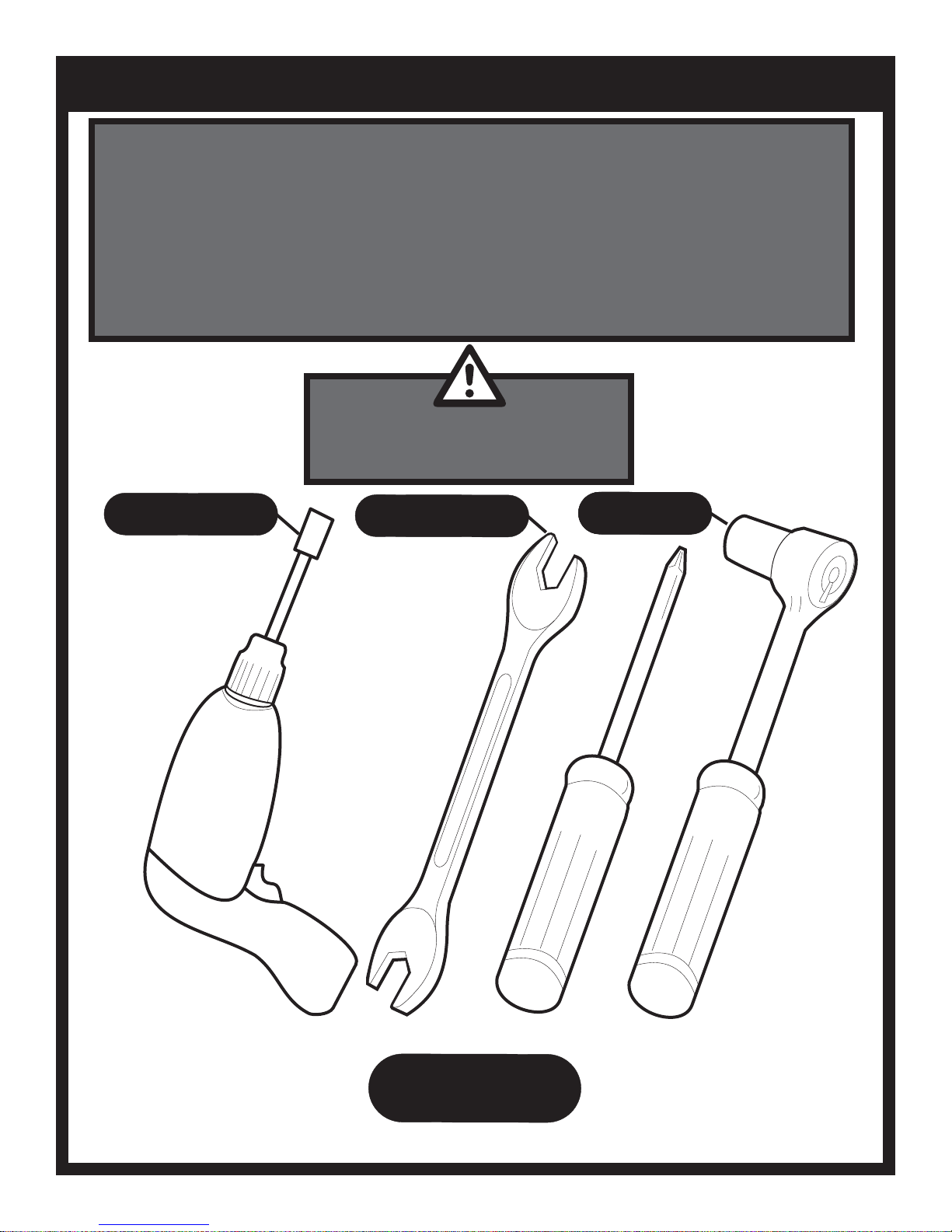
CAUTION:
Parts may have sharp edges. For your safety
wear leather work gloves and handle parts
carefully during unpacking and assembly.
3/8” and 7/16”
3/8” and 7/16”
5/16”
REQUIRED
3/8”, 7/16” and 3/4”
REQUIRED
3/8” and 7/16”
REQUIRED
REQUIRED
REQUIRED
B102271-1-0615 Page 5
TOOLS
REQUIRED
Page 6
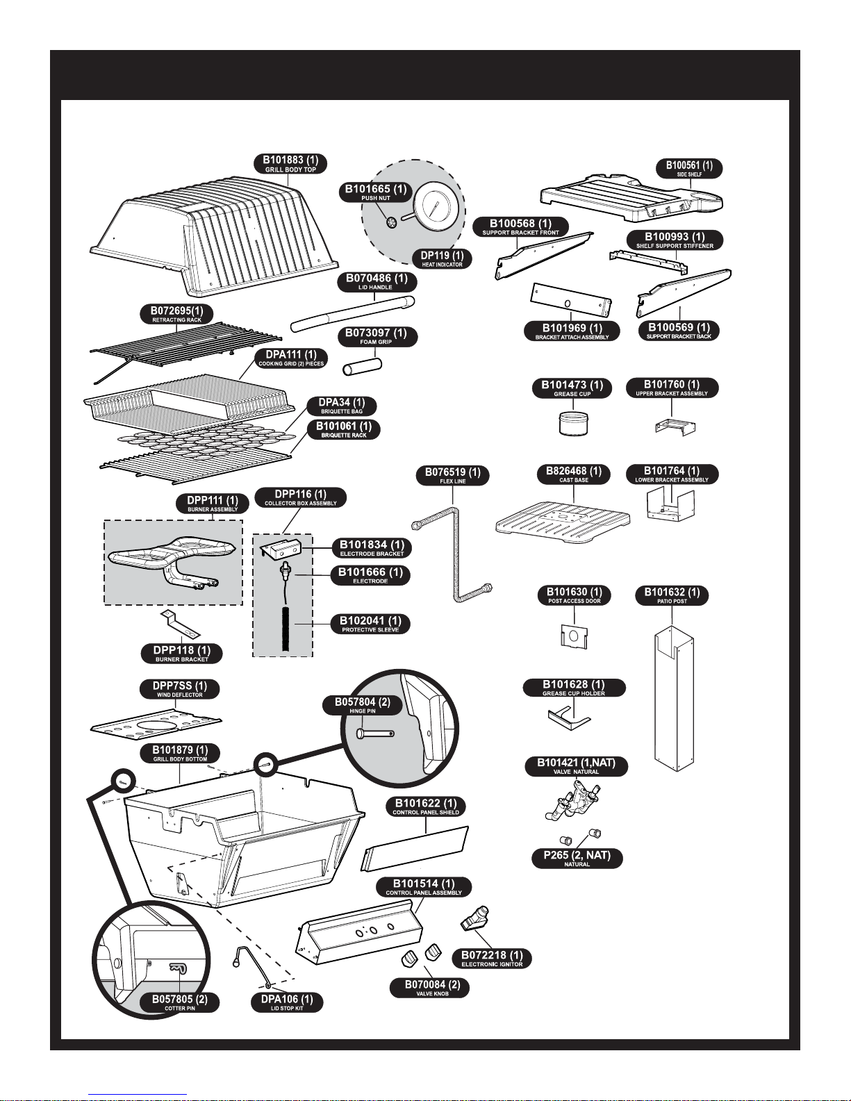
P3PK7 SERIES PARTS DIAGRAM
B102271-1-0615Page 6
Page 7
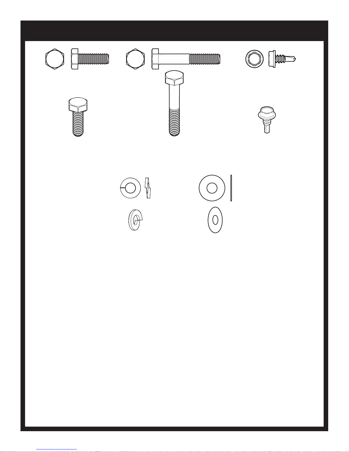
POST HARDWARE PACK - B102001
HEX HEAD BOLT,
SS,1/4-20 X 3/4
B063096
(4)
LOCK WASHER,
1/4 ID X 1/2 OD
B100139
(4)
HEX HEAD BOLT,
SS,1/4-20 X 1-1/2
B100112
(4)
SELF-DRILLING
HEX HEAD SCREW,
SS,10-24 X 1/2
B101569
(13)
FLATWASHER,
SS,1/4 ID X 5/8
OD
B076332
(4)
B102271-1-0615 Page 7
Page 8
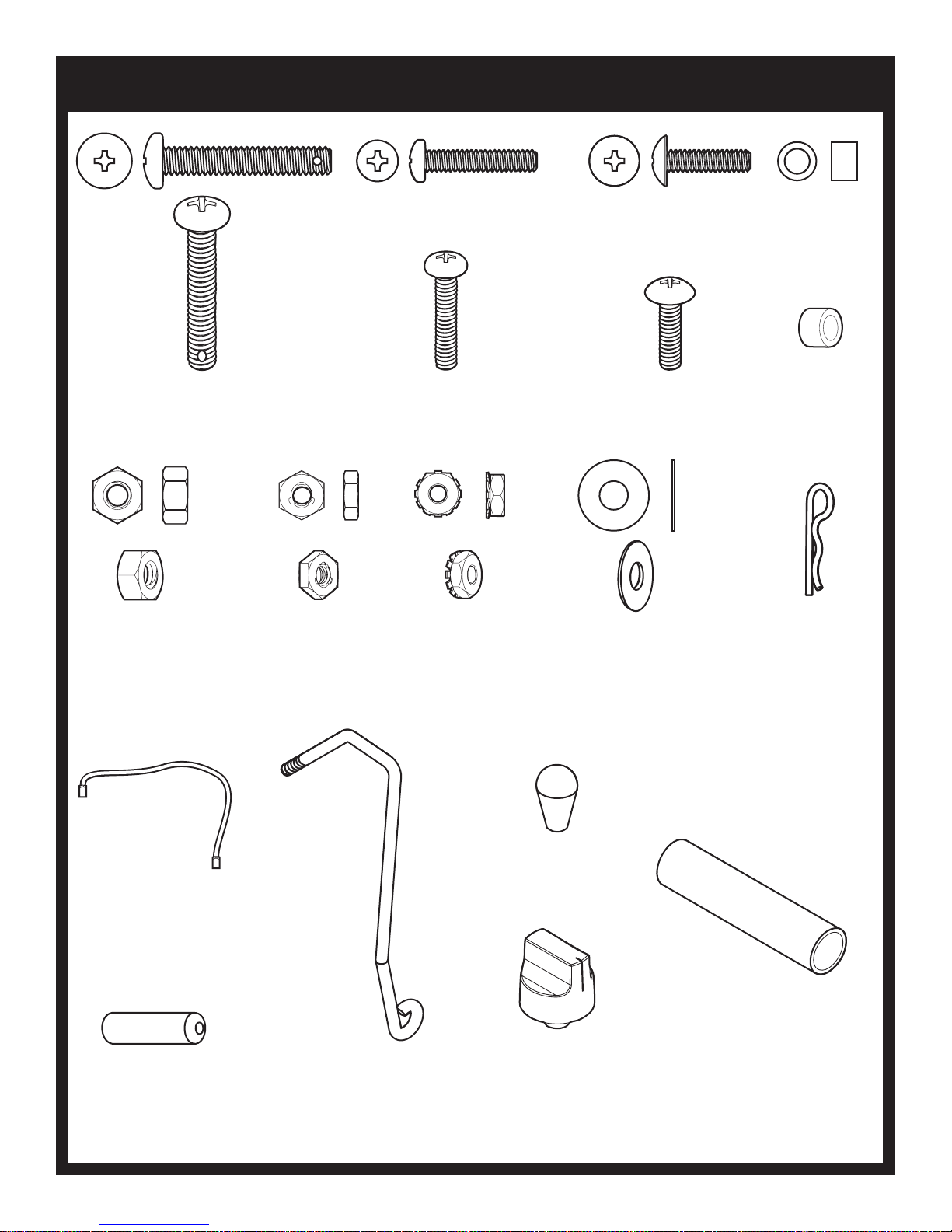
GRILL HEAD HARDWARE PACK - B102155
PHILLIPS PAN HEAD SCREW,
SS,1/4-20 X 1-1/2
B101649
(1)
HEX NUT,
SS,1/4-20
B076331
(1)
HEX LOCKNUT,
SS,10-24
R4021
(1)
PHILLIPS PAN HEAD SCREW,
SS,10-24 X 1
B073978
(2)
KEPS NUT,
SS,10-24
B073967
(3)
PHILLIPS TRUSS HEAD SCREW,
10-24 X 3/4
B100128
(1)
FLATWASHER,
1/4 ID X 5/8 OD
B076332
(2)
SPACER
B662325
(1)
COTTER PIN
B057805
(1)
GROUND
WIRE
B072684
(1)
BATTERY, AA
B076529
(1)
LID, STOP
B076521
(1)
KNOB,TAPERED
B100098
(1)
FOAM GRIP
B073097
(1)
KNOB
B070084
(2)
B102271-1-0615Page 8
Page 9
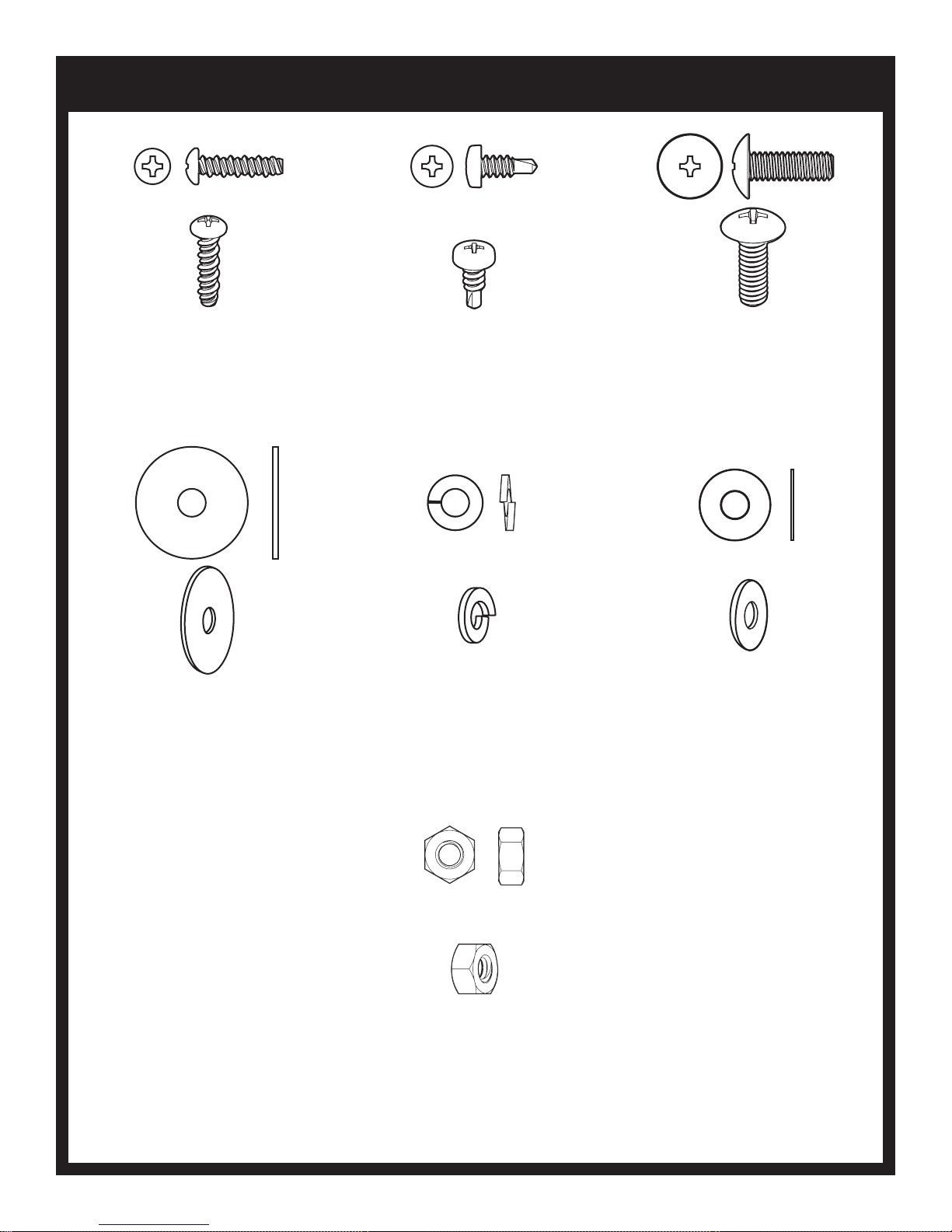
SHELF HARDWARE PACK - B101658
PHILLIPS PAN HEAD SCREW,
10-16 X 3/4
B100563
(4)
FLATWASHER,
SS,1/4 ID X 1
OD
B101640
(2)
SELF-DRILLING PHILLIPS PAN HEAD SCREW,
SS,10-16 X 1/2
R4059
(2)
LOCK WASHER,
1/4 ID X 1/2 OD
B076333
(2)
PHILLIPS TRUSS HEAD SCREW,
SS,1/4-3/4
B072217
(2)
FLATWASHER,
1/4 ID X 5/8 OD
B076332
(2)
B102271-1-0615 Page 9
HEX NUT,
SS,1/4-20
B076331
(2)
Page 10
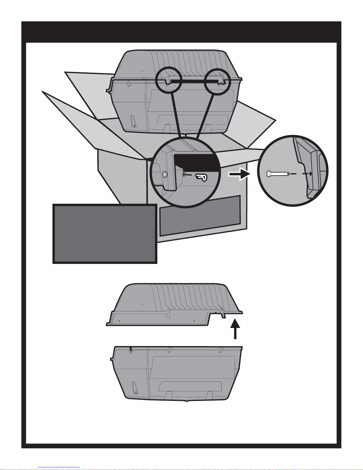
UNPACK AND REMOVE LID
REMOVING LID
To ease assembly, remove Grill Lid
and Warming Rack. Remove Warming
Rack and set aside. Remove the two
Pins and Clips at the rear of the Grill
Lid and set aside. After Pins, Lid and
Warming Rack have been removed,
remove the contents from inside the
Grill.
BROILMASTER
PREMIUM GRILLS
B102271-1-0615Page 10
Page 11
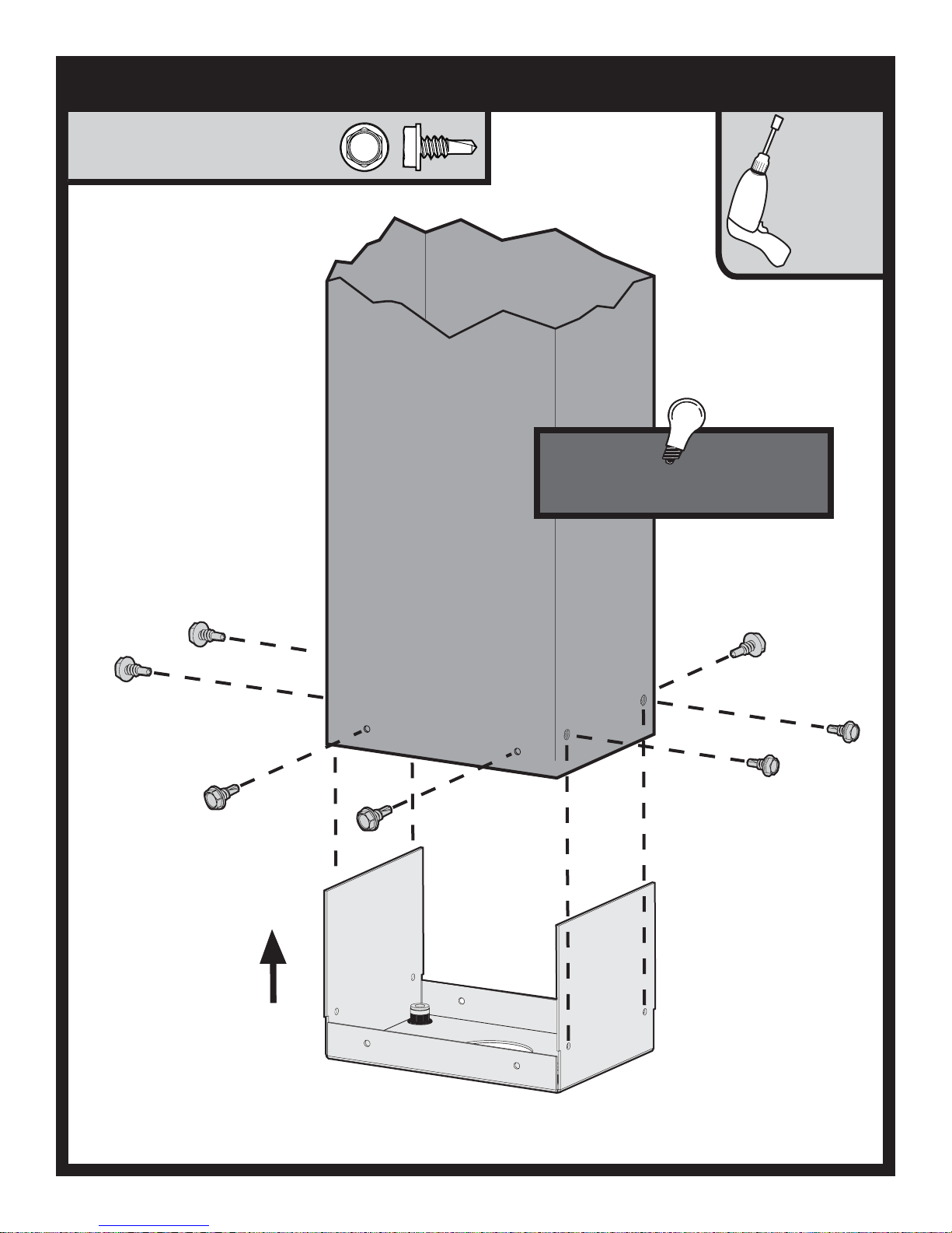
ATTACH LOWER BRACKET
SELF-DRILLING HEX HEAD SCREW,
SS,10-24 X 1/2
B101569 (8)
5/16”
The large rectangular cut out is located at
the front of post near the top.
B102271-1-0615 Page 11
Page 12
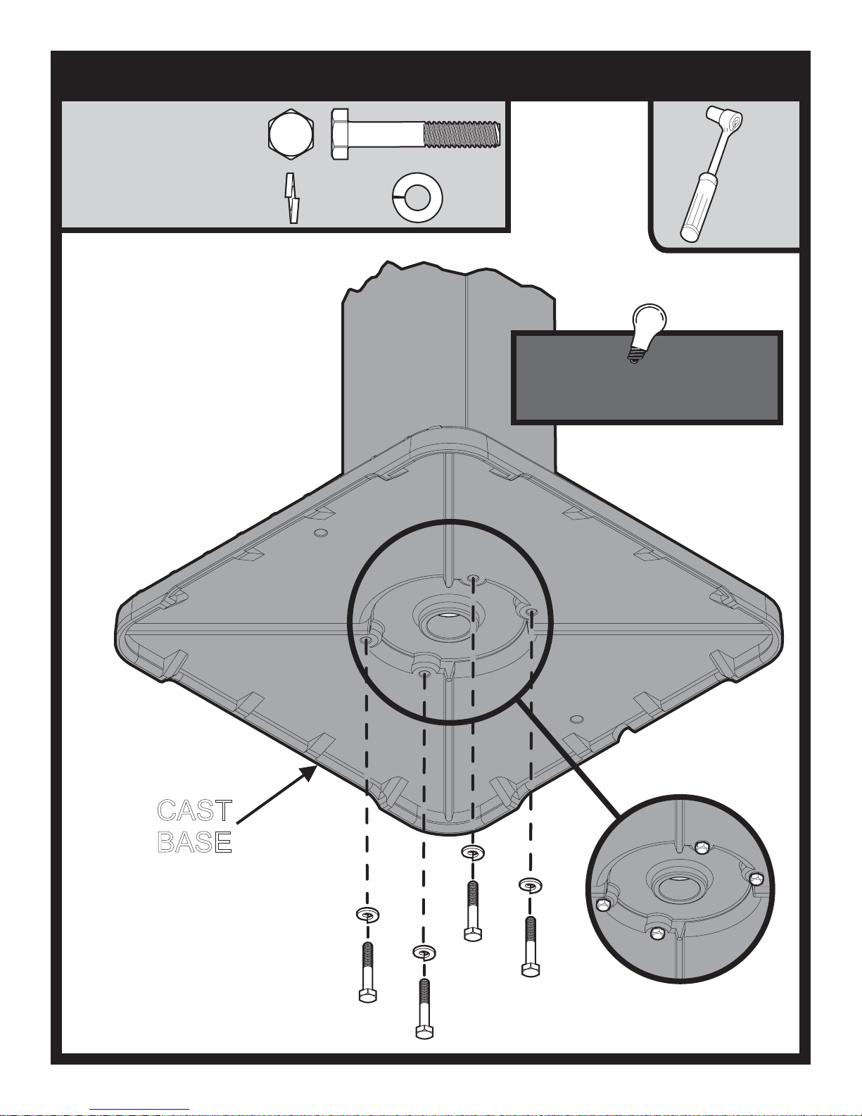
ATTACH BASE TO POST
HEX HEAD SCREW,
SS,1/4-20 X 1 1/2
B100112 (4)
LOCK WASHER,
1/4 ID X 1/2 OD
B100139 (4)
. .
7/16”
Make sure that the large upper
rectangular cut out is facing in the
direction that you want your grill to face.
CAST
BASE
B102271-1-0615Page 12
Page 13

INSERT FLEX LINE THROUGH POST
Insert the stainless steel Flex Tube
Assembly into the Post. The inlet side of
the Gas Tubing may protrude from the
bottom of the Patio Base or through the
large square hole in the back of the
square Post.
Anchor the Base to your patio using
(2) Holes in the Base.
(Hardware not Included)
Note: Make sure that large upper
rectangle cut out is facing in the direction
that you want your grill to face.
B102271-1-0615 Page 13
Do not attempt to cut or alter the flex
tube in any way.
Page 14
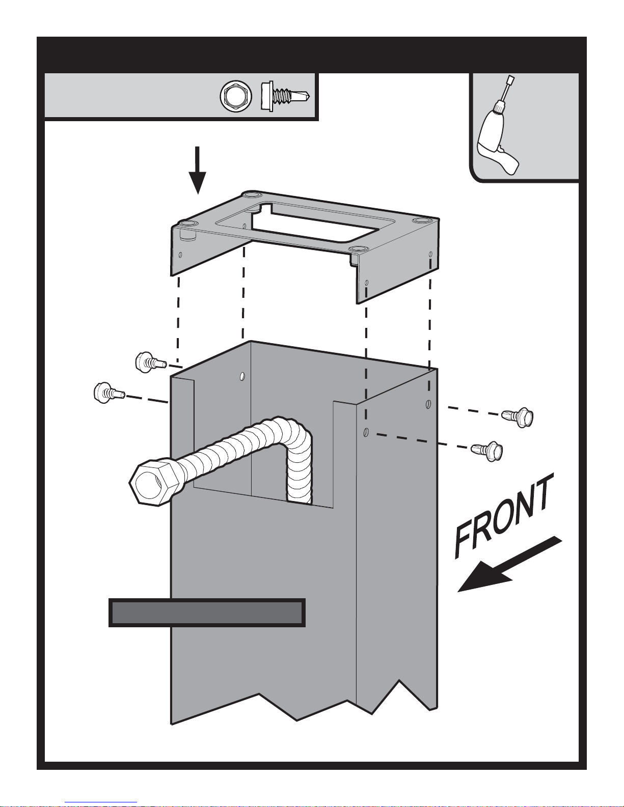
ATTACH UPPER BRACKET
SELF-DRILLING HEX HEAD SCREW,
SS,10-24 X 1/2
B101569 (4)
5/16”
Slide the Upper Bracket into the Post and
secure with four Self Drill Screws.
B102271-1-0615Page 14
Page 15
GREASE CUP HOLDER PLACEMENT
Remove Protective film applied
to Grease Cup Holder prior to
install. Snap Grease Cup Holder
to top of Post.
Use only the supplied Grease Cup or
noncombustible containers for the
Grease Cup (aluminum or tin cans).
B102271-1-0615 Page 15
Page 16

INSERT BURNER HOLD-DOWN BOLT
PHILLIPS PAN
HEAD SCREW
SS, 1/4-20 X 1-1/2
B101649 (1)
HEX NUT,
SS, 1/4-20
B076331(1)
.
7/16”
B102271-1-0615Page 16
Page 17

ATTACH BOTTOM CASTING TO POST
HEX HEAD BOLT
SS, 1/4-20 X 3/4
B063096 (4)
FLAT WASHER,
SS, 1/4 ID X 5/8 OD
B076332 (4)
.
7/16”
B102271-1-0615 Page 17
Page 18

ATTACH SIDE SHELF
PHILLIPS TRUSS HEAD SCREW,
SS, 1/4-20 X 3/4
B072217 (2)
FLAT WASHER,
1/4 ID X 5/8 OD
B076332 (2)
FLAT WASHER,
SS, 1/4 ID X 1 OD
B101640 (2)
LOCK WASHER,
1/4 ID X 1/2 OD
B076333 (2)
HEX NUT,
SS, 1/4-20
B076331 (2)
.. . .
. . .
. .
..
7/16”
CORRECT
Ensure that the Side
Shelf Bracket Assembly
is installed so that the
Match Light Access
Hole is on the bottom.
INCORRECT
B102271-1-0615Page 18
Page 19

ATTACH SIDE SHELF
PHILLIPS PAN HEAD SCREW,
10-16 X 3/4
B100563 (4)
B102271-1-0615 Page 19
Page 20

ATTACH SIDE SHELF
SELF-DRILLING PHILLIPS PAN HEAD SCREW,
SS, 10-16 X 1/2
R4059 (2)
Leave Screws loose
until next step.
B102271-1-0615Page 20
Page 21

ATTACH SIDE SHELF
B102271-1-0615 Page 21
Hang the side Brackets on the lower
Pins of the Bracket attach assembly.
Tighten the two 10-16 x 1/2 Phillips
screws from previous step.
Page 22

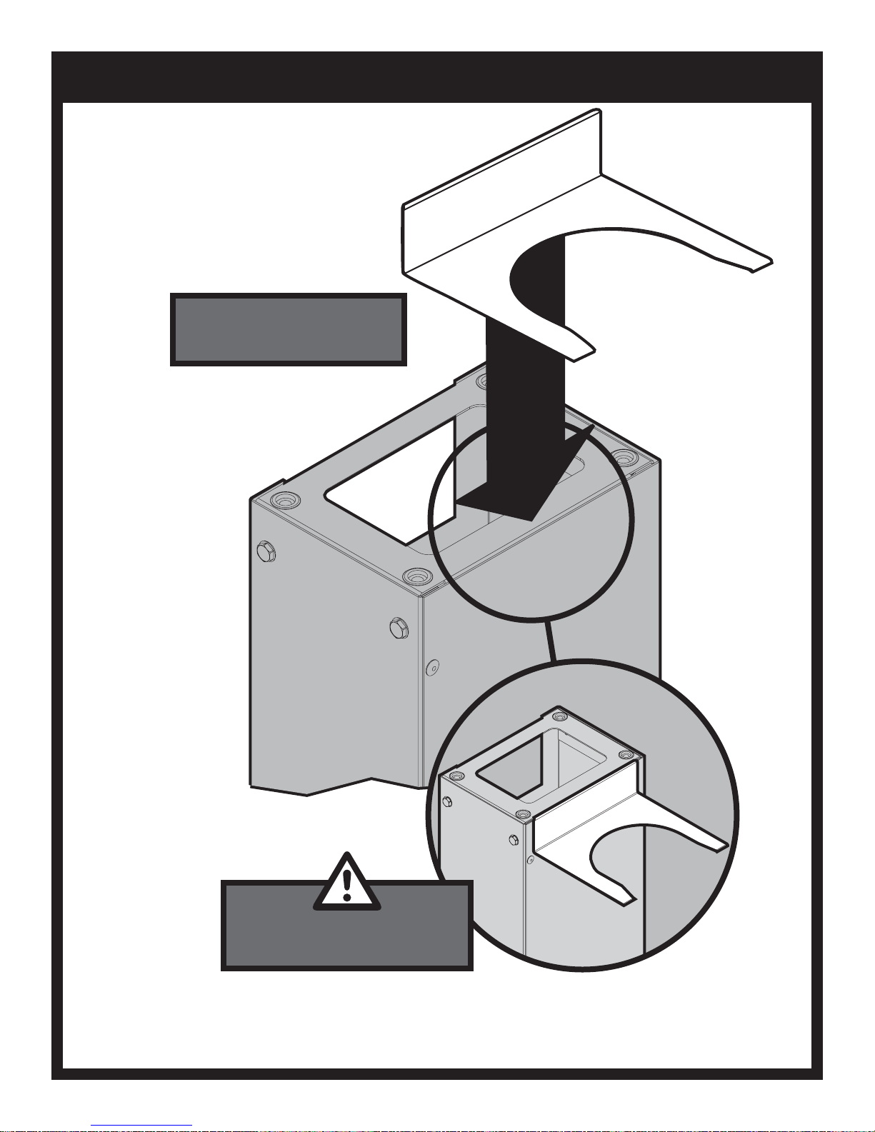
WIND DEFLECTOR PLACEMENT
Place the Wind Deflector in the bottom
Casting.
The Wind Deflector cannot
be installed until after the bottom
Casting is installed on the Post.
B102271-1-0615Page 22
Page 23

INSERT CONTROL PANEL
KEPS NUT,
SS, 10-24
B073967(2)
3/8”
Ease the Control Shield over the studs on
the Control Panel. Then insert the two
studs through the holes on the front of the
grill. Remove Plastic Cover on label.
CONTROL
PANEL
SHIELD
CONTROL
PANEL
B102271-1-0615 Page 23
Page 24

ATTACH IGNITER WIRE
Connect the ground wire to the ground
lug on the Collector Box before
installing the burner into the casting.
COLLECTOR BOX
B102271-1-0615Page 24
Page 25

INSTALL BURNER ASSEMBLY
COTTER PIN,
B057805(1)
1
Slide the Venturi on to the Valve
Assembly to the left as shown.
Raise the unsecured end of the Burner
Bracket and slip it over the Phillips
Truss Head Screw. The screw will fit
into the hole on the Burner Bracket.
Insert Cotter Pin.
Note: Ignitor Wires run through center
hole with Venturi.
2
3
Insert the Burner Assembly into
the Grill bottom with the Venturi
Tubes facing the front of the Grill.
4
B102271-1-0615 Page 25
5
Page 26

CONNECT IGNITER LEADS
IGNITER
Route Leads from Burner through
rectangle cutout and secure to Ignitor
Terminals (polarity is not important).
B102271-1-0615Page 26
Page 27

KNOB AND BATTERY PLACEMENT
Unscrew the Ignitor Knob from the
Control Panel, and insert AA Battery,
positive side up, and replace Ignitor
Button.
B102271-1-0615 Page 27
AFTER
Page 28

INSTALL LID STOP
PHILLIPS TRUSS HEAD SCREW,
SS,10-24 X 3/4
B100128 (1)
HEX LOCK NUT,
SS, 10-24
R4021 (1)
FLAT WASHER
1/4 x 5/8 OD
B076332 (2)
SPACER,
B662325 (1)
3/8”
LID STOP
ROD
Screw the black Knob onto the Lid
Stop. Do not overtighten.
KNOB
B102271-1-0615Page 28
Page 29

INSTALL HANDLE
PHILLIPS PAN HEAD SCREW,
SS,10-24 X 1
B073978 (2)
Tip: For ease of installation, lightly
lubricate the inside of the Foam Grip with
Liquid Soap before twisting it on to
Handle.
B102271-1-0615 Page 29
Page 30

REINSTALL LID
HINGE PIN,
(FROM PREVIOUS STEPS)
B057804 (1)
COTTER PIN,
(FROM PREVIOUS STEPS)
B057805 (1)
B102271-1-0615Page 30
Page 31

INSTALL RACKS
Place the 'Char-Master' Briquets in a
single layer evenly on your grill's
briquet rack. DO NOT dump them
onto the briquet rack. A single layer
of 'Char-Master' Briquets is all that's
needed.
There may be some briquets left
over. Save them for future use.
Before cooking, always preheat the
grill as directed by the grill's
operating instructions. Hot
briquets give better flavor and
allow quicker cooking.
1
COOKING GRID POSITION
2
COOKING GRID POSITION
3
COOKING GRID POSITION
B102271-1-0615 Page 31
Page 32

B
D
A
C
INSTALL RACKS
C
A
B
D
B102271-1-0615Page 32
Page 33

NATURAL GAS GRILLS
3/4”
B102271-1-0615 Page 33
Attach the flexible stainless steel
gas line (provided with the
Broilmaster post) to the fitting on the
burner control valve mounted on the
control panel. Tighten this
connection with a wrench.
Page 34

NATURAL GAS GRILLS
Grill Location
This grill is designed for outdoor use only.
Never operate your grill in any building, garage, or other
enclosed area. Never operate your grill in a recreational vehicle
or boat. Never operate your grill under any combustible materials,
such as carports, covered porches, awnings, or overhangs.
CAUTION
Keep the sides of the grill at least 16 inches from any
combustible material. Keep the back of the grill at least
18 inches from any combustible material. Placing a hot
grill too close to a building or other combustible mate-
rial may lead to re, property damage, or personal injury.
Combustible materials include fences, patio furniture,
and your home.
Keep the area around the grill clear to ensure proper ventilation.
WARNING
Do not install or operate this grill where gasoline or other
ammable materials are used or stored. Failure to comply
with this warning could result in explosion or re causing
property damage or personal injury.
Gas Type
The type gas required for your grill can be determined from the
product identication label located on the grill’s control panel.
Questions regarding different types of gases should be directed
to your local gas supplier.
Connection Requirements
Broilmaster natural gas grills are not equipped with pressure
regulators. Your gas grill operates at a manifold pressure of
seven inches water column. (Your natural gas technician will
understand what this means.)
Arrange with your local gas company or licensed contractor to
have a gas supply line connected to the inlet of the stainless
steel ex tube assemble. The gas supply must have a shutoff
valve that is close to the post in case of emergency and must
be shutoff when the grill is not in use.
Connect your grill this coupling using the twelve foot exible
hose with a quick disconnect tting (available for purchase from
your Broilmaster dealer.)
CAUTION
The grill and its individual shutoff valve must be discon-
nected from the gas supply piping system during any
system pressure testing at test pressures in excess of
1/2 PSIG.
CAUTION
The grill must be isolated from the gas supply piping sys-
tem by closing its individual manual shutoff valve during
any pressure testing of the gas supply piping system at
test pressures equal to or less than 1/2 PSIG.
CAUTION
Never use Liquid Propane (LP) gas in a grill designed
for Natural gas, or Natural gas in a grill designed for
Liquid Propane gas. Questions regarding different types
of gases should be directed to your local gas company.
B102271-1-0615Page 34
Page 35

GREASE CUP AND ACCESS DOOR PLACEMENT
SELF-DRILLING HEX HEAD SCREW,
SS,10-24 X 1/2
B101569 (1)
Install Grease Cup by sliding it in
the cutout provided in the Grease
Cup Holder.
5/16”
Secure Access Door.
B102271-1-0615 Page 35
21 3 4
Page 36

COMPLETED ASSEMBLY
Thank you for purchasing a Premium Gas Grill and we hope you
enjoy years of great meals prepared on your Broilmaster.
Please feel free to visit the Broilmaster Facebook page
and share photos of your Broilmaster grill.
Thank You!
Arrange with your local gas
company or licensed contractor
to have a gas supply line
connected to the inlet of the
stainless steel flex tube
assembly. The gas supply must
have a shutoff valve that is close
to the post in case of emergency
and must be shutoff when the
grill is not in use.
B102271-1-0615Page 36
Page 37

OPERATION - NATURAL GAS GRILL
Check for Gas Leaks
Check for gas leaks every time your Broilmaster gas grill has
not been used recently, or when using a natural gas grill for the
rst time.
CAUTION
Do not use an open ame when checking for leaks.
Checking for leaks with an open ame may lead to a re or
explosion, resulting in property damage or personal injury.
To check for gas leaks:
1. Use water dish and a little dish washing liquid to make a
soapy solution.
2. Turn OFF the knob on the control panel.
3. Turn ON the gas at the supply or cylinder. A hissing sound
indicates a leak. Turn OFF the gas and repair the leak.
4. Apply the soapy water solution to all gas connections.
5. Look for bubbles. Bubbles indicate a leak.
6. If you see bubbles turn OFF the gas and repair the leak.
7. Turn the gas back ON and repeat the above procedures until
all leaks are repaired.
Air Shutter Adjustment
The venturi air shutter(s) are preset at the factory so that after
ve minutes the burner ames are blue with well dened cones.
If, after ve minutes the ame is yellow, or there is a gap between
the burner and the ame, adjust the venturi air shutter as follows:
1. Turn gas OFF and let the burner cool.
2. Loosen shutter set screw.
3. Close the air shutter to the minimum opening.
4. Light the burner, wait ve minutes and then carefully open
the air shutter until the ame is blue and well dened.
5. Retighten the set screw.
Operating Instructions
Lighting with the Electric Igniter
CAUTION
If a burner fails to light after 5 seconds, turn the burner
OFF for 5 minutes, to allow the gas to clear, then try again.
1. Open the grill lid.
2. Turn burner knob CLOCKWISE to the OFF position.
3. Turn ON the gas at the source.
4. With the grill lid open, push and turn the burner control knob
COUNTERCLOCKWISE to Hi.
5. Push and hold the igniter button until the burner lights
(approximately 5 seconds).
6. If a burner does not light, turn OFF all gas and refer to
the Troubleshooting section of this manual.
Lighting with a Match
CAUTION
If a burner fails to light after 5 seconds, turn the burner
OFF for 5 minutes, to allow the gas to clear, then try again.
1. Open the grill lid.
2. Turn the burner knob CLOCKWISE to the OFF position.
3. Turn ON gas at the source.
4. With the grill lid open, push and turn the burner control knob
COUNTERCLOCKWISE to HI.
5. Insert a long wooden lighted match through the lighter hole
on either side of the grill. See Figure Below.
6. If a burner does not light, turn OFF all gas and refer to the
Troubleshooting section of this manual.
Heat Indicator Recalibration
The heat indicator can be recalibrated if needed. Remove the heat
indicator from the grill and place the probe end in a pot of boiling
water. Set the heat indicator by turning the nut on the back until
it reads 212 degrees. The indicator is now set.
B102271-1-0615 Page 37
LIGHTING WITH A MATCH
Page 38

OPERATION - NATURAL GAS GRILL
Before Cooking
Before cooking on a grill for the rst time, it should be broken
in to burn off any oil residue from the manufacturing process.
1. Raise the grill lid.
2. Light grill burner.
3. Burn on HI for ten minutes.
4. Close the lid and burn on HI for an additional ten minutes.
5. Turn OFF gas. The grill is now ready for use.
Preheating
Before cooking on a gas grill, allow the grill to preheat on HI for
5 minutes with the lid closed.
This uses very little fuel and provides better avor.
Electrical Accessories
If an electrical accessory (e.g. rotisserie) is used on your grill, the
accessory must be electrically grounded in accordance with local
codes or, in the absence of local codes, with the National Electric
Code, ANSI/NFPA 70. In Canada, the electrical accessory must
be electrically grounded in accordance with the applicable section
of the current Canadian Electrical Code, CSA C22.1.
Any electrical accessory should be equipped with a threeprong (grounding) plug, and plugged into a properly grounded
three-prong receptacle or wall outlet. Do not cut or remove the
grounding prong from the plug.
If an extension cord is required, use only a three-prong cord and
plug into a properly grounded receptacle as described above.
Do not expose an electrical accessory to water. Avoid using
any electrical accessory in wet weather as it may present a
shock hazard.
Keep any electrical cord and fuel supply hose away from all
heated surfaces.
B102271-1-0615Page 38
Page 39

MAINTENANCE
MAINTENANCE
Cleaning the Grill
CAUTION
To prevent injury, use care when cleaning a hot grill.
Buy a good grill brush. Inexpensive grill brushes tend to lose
their metal bristles, which can stick to your cooking grids and
become embedded in foods.
A grill builds up a patina of smoke residue. The “seasoning” is
normal and actually enhances the avor of your foods. If the
build-up grows too think, it can ake off and fall onto your food.
To remove excess build-up, let the grill cool completely and then
brush thoroughly with a high-quality grill brush.
Note: Do not use a commercial cleaner on the cooking grid.
For baked on residue use grill brush on the cooking grid
and other components.
Burn Off
This process is much like that used in self-cleaning ovens and
is most efcient when completed after each use of the grill.
CAUTION
cause a re, or ashback, around the obstructed venturi tubes
and may damage to components beneath the grill or an unsafe
condition. To reduce risk, inspect and clean the venturi tubes
at least twice per year and more often if spiders are active. If
the grill has been unused for an extended period of time inspect
the tubes before using the grill.
Cleaning Venturi Tubes
1. Remove the cooking grids and briquette rack.
2. Remove the burner from the grill.
3. Lay the burner face down and remove the four retaining
screws from the venturi tube plate and the burner.
See Figure Below.
4. Use a small exible brush to remove any debris for the
tube(s).
5. Flush with water.
6. Allow the tube(s) to dry before reinstalling.
7. Reattach the venturi, collector box, and bracket in the same
order removed.
8. Reinstall burner, briquette rack, and cooking grids.
Do not open the grill during the burn off process.
Opening the grill during the burn off process may cause
a sudden grease re are up that could burn your face
and arms. Wait until the grill has cooled before opening.
1. Turn gas knob to HI. Close lid and allow the grill to burn for
ten minutes, or until no smoke is present. Do not allow the
grill to burn for more than 30 minutes.
2. Turn gas knob and supply to OFF and allow the grill to cool.
3. Wipe COOL grill with a damp cloth to remove soot.
Grill Bottom
Periodically remove cooking grids to clean the interior of the
grill. Scrape off baked on residue with a putty knife or brush and
rinse with water. Clean the bottom air holes with a small knife.
Burner Maintenance
Stainless steel burners often turn reddish brown after use. This
does not effect the performance of the grill. When cleaning the
interior of the grill, remove the burners and clean with a brush.
Wash with water and a mild detergent.
Grease Cup
Empty periodically.
CLEANING VENTURI TUBES
Exterior Cleaning
Turn off the grill and allow it to cool before cleaning. Never use
aerosol sprays or ammable cleaners on or near a hot grill.
Do not use abrasive pads or cleaners on stainless or painted
components.
Clean the grill exterior regularly with a solution of mild detergent
and hot water.
Touch-up paint is available from your dealer.
Broilmaster protective covers are recommended. Clean stainless steel components with a stainless steel cleaner available
in most hardware stores.
Venturi Tubes
The venturi tubes allow air and gas to mix prior to burning,
ensuring an efcient ame. Spiders or other small insects may
build webs or nests inside the tubes obstructing air ow. This can
B102271-1-0615 Page 39
Briquettes
If the briquettes did not come clean during burn off, wait for the
grill to cool and then turn them over. The residue will burn off
during the next warm-up.
Page 40

TROUBLESHOOTING
Although we have attempted to ensure that your grill will operate properly and
satisfactorily, sometimes problems do arise. The following troubleshooting guide lists several
possible problems and their probable cause and solution.
Do not repair or replace any part of the grill unless specically recommended in this manual.
All other service should be referred to a qualied technician.
Problem Cause Solution
Burner will not light. Gas injector not inserted in venturi
tube.
Clogged gas injector. Remove gas injector from gas
Spider webs in venturi tubes. Clean venturi tubes.
Misalignment of collector box and
burner.
Out of gas Natural model, turn on gas at
Dead battery. Replace with AA Alkaline
Inadequate grill temperature.
Poor combustion. Adjust air shutter.
Misalignment of venturi tube and
gas injector.
Inadequate gas pressure. Contact gas supplier for
Incorrect orice/valve setting. Refer to gas conversion
Realign/engage gas injector
with the venturi tube.
control assembly and clean.
See Maintenance Section.
Position electrode properly.
Clean collector box.
source.
battery.
Realign/engage gas injector
with the venturi tube.
assistance.
instructions in this manual.
Flames blow out. Cold grill. Preheat grill at least 5 minutes
Misalignment of burner tube and
gas injector.
Poor combustion. Adjust air shutter.
Extreme wind. Turn or shield grill.
Yellow ames. Air shutter improperly set. Open air shutter
Spider webs in venturi tubes. Clean venturi tubes.
Seasoning salts on burner. Clean by washing burner with
Oil lm on burner. Allow burner to operate on HI
on HI with the grill lid closed.
Realign/engage gas injector
with the burner tube.
See Maintenance Section.
mild detergent.
for 10-15 minutes.
B102271-1-0615Page 40
Page 41

IMPORTANT SAFETY INFORMATION
WARNING
Spiders and insects can nest in gas grill burners causing the gas to ow from the front of the burner
and ignite under the control panel. This is very dangerous and can damage the grill, making it
unsafe to operate. Inspect the grill at least twice per year and more often if spiders are active.
Be sure all grill controls are turned off and the grill is cool before using any type of aerosol cleaner
on or around the grill. The chemical that produces the spraying action could, in the presence of
heat, ignite or cause metal parts to corrode. Do not operate the grill under unprotected
combustible construction. Use only in well ventilated areas. Do not use in buildings, garages,
sheds, breezeways or any enclosed areas.
Keep the area around the grill free from combustible materials, trash, or combustible uids and
vapors such as gasoline or charcoal lighter uid. Do not obstruct the ow of combustion and
ventilation air. Keep the back of the cart free and clear from debris.
If the grill is stored indoors ensure that it is cool. If propane is used, the cylinder must be unhooked
and the propane cylinder stored outside in a well-ventilated area, out of reach of children.
Never use the grill in windy conditions. If located in a consistently windy area (oceanfront, mountain
top, etc.) a windbreak will be required.
Always adhere to the specied clearance.
Keep electrical cords always from the heated areas of the grill.
Do not use the grill for cooking excessively fatty meats or products, which promote are-ups.
Keep Children Away from the Grill at All Times
Never leave children unattended near the grill. Teach them to stay away even when you are not
cooking, as the grill can remain hot after it is turned off.
Never allow children to sit, stand or play on or around the grill at any time. Do not store items of
interest to children around or below the grill or in the cart.
Never allow children to crawl inside of a cart or island enclosure.
B102271-1-0615 Page 41
Page 42

IMPORTANT SAFETY INFORMATION
Practice Safe Grilling
Do not wear loose tting clothing or readily ammable clothing (such as synthetics) around the grill.
Never let clothing, pot holders, or other ammable materials come in contact with or too close to
any grate, burner or hot surface. Fabric may ignite and result in personal injury.
Use only dry pot holders. Using a damp pot holder on a hot surface may cause burns from steam.
Do not use towels or bulky cloth in place of pot holders. Do not let pot holders touch hot cooking
grids. Never use a sponge on a hot surface, as it may cause steam burns. Protect your hand with
an oven mitt or pot holder when opening the grill lid. Never lean over an open grill.
Use heat-proof cookware and tools specically designed for grilling. Other types of material may
shatter with sudden temperature changes or melt from extreme heat. Use tools with insulated
handles and keep them away from the grill to avoid heat build-up.
Do not spray aerosol oil or butter or pour liquid oil into the grill. Doing so will cause a ash re that
can burn you.
Grease is ammable. Let grease cool before attempting to handle it. Avoid letting grease deposits
collect in the bottom of the grill. Clean your grill often.
Do not use aluminum foil to line the cooking grids or grill bottom. This can disrupt combustion air
ow or trap excess heat in the control area. Excess heat can melt knobs or igniters, and increase
the chance of personal injury. The drip tray accessory may be lined with aluminum foil.
Do not heat unopened food containers - such as cans, jars, and sealed pans. Pressure build-up
may cause the container to burst.
When lighting a grill, always open the lid rst and pay close attention to what you are doing. Turn
one burner knob to HI, press the igniter button and count to ve.
For proper lighting and performance of the burners keep the ports clean.
Clean the grill with caution. Avoid steam burns; do not use a wet sponge or cloth to clean the grill
while it is hot. Some cleaners produce noxious fumes or can ignite if applied to a hot surface.
B102271-1-0615Page 42
Page 43

COOKING TIPS
Cook Food To Proper Temperatures
Cooking food safely requires that you raise the internal temperature of the meat high enough and for a long enough
period of time to kill any food-borne bacteria that may cause illnesses.
Color is not the best indicator that food is safe to eat. Use a high-quality probe thermometer to be sure your food is
properly cooked. Place the tip of an instant-read thermometer into the center of the thickest part of the food but at
least 1/2 inch deep. Read the temperature after about 10 seconds. Follow the temperature guidelines for the type of
food you’re cooking.
The following guidelines are from the U.S. Food and Drug Administration Center for Food Safety and Applied Nutrition.
Cook to Internal Temp
Meat & Poultry Medium Rare Medium Well Done
Fresh Beef - Medium Rare 145°F 160°F 170°F
Ground turkey, chicken 165°F
Ground veal, beef, lamb, pork 145°F with 3 minutes of rest and then turn
Fresh Pork - Medium 160°F 170°F
Chicken - whole 165°F
Turkey - whole 165°F
Poultry breasts, roast 165°F
Poultry thighs, wings 165°F
Stufng (cooked alone or in bird) 165°F
Duck and goose 180°F
Fresh Veal - Medium Rare 160°F
Fresh Lamb - Medium Rare 145°F 160°F 170°F
Ham - fresh (raw) 145°F 160°F 170°F
Ham - pre-cooked (reheat) 140°F
Seafood
Fish Cook until esh turns opaque and akes easily with a fork.
Shrimp, lobster, crab Cook until shells turn red and esh becomes pearly opaque.
Scallops Should turn milky white or opaque and rm.
Clams, mussels, oysters Cook until shells open.
*The above temperature settings are a guide, the temperatures may vary due to wind and outside ambient temperatures.
B102271-1-0615 Page 43
Page 44

WARRANTY TERMS
Empire Comfort Systems Inc. warranties this Broilmaster premium gas grill to be free from defects at the time of purchase and
for the periods specied below. Broilmaster Premium Gas Grills must be installed by a qualied technician and must be maintained and operated safely, in accordance with the instructions in the owner’s manual. This warranty applies to the original
purchaser only and is not transferable. All warranty repairs must be accomplished by a qualied gas appliance technician.
Limited Lifetime Parts Warranty – Against Rust-Through
If the items listed below fail because of defective workmanship or material, Empire will repair or replace at Empire’s option.
The limited lifetime warranty provides one-time replacement of a covered component.
• Aluminum Grill Housing (except paint)
• Stainless Steel Cooking Grids and Stainless Steel Griddles
• Select Stainless Steel Components – Cart, Mounting, Bowtie Burner, Side Burner (DPSBSS), Side Burner Housing, and Warming
Rack
• Stainless Steel Built-In Components – Built-In Kits for 3-Series Grill Heads, Door Kit, Tilt-Out LP Tank Door, and Vent Register Kit
Limited Ten-Year Parts Warranty – Against Rust-Through
If the items listed below fail because of defective workmanship or material, Empire will repair or replace at Empire’s option.
• Stainless Steel Burners H-Series, Q-Series and R3B
• Stainless Steel Drip Pan for Q-Series
• Side Burner (DPASBC), Side Burner Housing (BSA)
Limited Five-Year Parts Warranty – Against Rust-Through
If the items listed below fail because of defective workmanship or material, Empire will repair or replace at Empire’s option.
• Infrared Burners on R3 or R3B
• Flare Buster™ Ceramic Flavor Enhancers
• Painted Electro-Galvanized Steel Components
• Stainless Steel Smoker Shutter
Limited Two-Year Parts Warranty – Against Rust-Through
If the items listed below fail because of defective workmanship or material, Empire will repair or replace at Empire’s option.
• Porcelain Coated Steel Briquette Racks
• Chrome-Plated Warming Rack
• Stainless Steel Flavor Screen
• Stainless Steel Heat Shield
Limited One-Year Parts Warranty
If the items listed below fail because of defective workmanship or material, Empire will repair or replace at Empire’s option.
• Valves, knobs, ignitors, labels, hoses, ttings, grease cups, drip buckets, and all other parts and accessories – including those made
from stainless steel – unless specied above
• Paint on Aluminum Grill Head
Duties Of The Owner
The appliance must be installed by a qualied installer and operated in accordance with the instructions furnished with the appliance.
A bill of sale, cancelled check, or payment record should be kept to verify purchase date and establish warranty period.
Ready access to the appliance for service.
What Is Not Covered
Damages that might result from the use, misuse, or improper installation or storage of this appliance.
Travel, diagnostic costs and freight charges on warranted parts to and from the factory.
Claims that do not involve defective workmanship or materials.
Unauthorized service or parts replacements.
Removal and reinstallation cost.
Inoperable due to improper or lack of maintenance.
The costs of a service call to diagnose a problem and labor for replacement or repairs.
How To Get Service
To make a claim under this warranty, please have your receipt available and contact your installing dealer. Provide the dealer with
the model number, serial number, type of gas, and purchase verication. The installing dealer is responsible for providing service and
will contact the factory to initiate any warranted parts replacements. Empire will make replace replacement parts available at the
factory. Shipping expenses are not covered. If, after contacting your Empire dealer, service received has not been satisfactory,
Contact: Consumer Relations Department
Replacement, Empire Comfort Systems Inc.,
PO Box 529, Belleville, Illinois 62222, or send an e-mail to
info@empirecomfort.com with “Consumer Relations” in the subject line.
Your Rights Under State Law
This warranty gives your specic legal rights, and you may also have other rights, which vary from state to state.
B102271-1-0615Page 44
Page 45

GRILL MAINTENANCE HISTORY
Date Maintenance Performed
B102271-1-0615 Page 45
Page 46

GRILL MAINTENANCE HISTORY
Date Maintenance Performed
B102271-1-0615Page 46
Page 47

MASTER PARTS DISTRIBUTOR LIST
To order parts under warranty, please contact your local Broilmaster dealer. See the dealer locator at www.broilmaster.com.
To provide warranty service, your dealer will need your name and address, purchase date and serial number, and the
nature of the problem. Please keep your receipt to establish ownership and date of purchase.
To order parts after the warranty period, please contact your dealer or one of the Master Parts Distributors listed below.
The Master Parts Distributor list changes from time to time. For the current list go to www.broilmaster.com and click on
the Parts button.
Note: Master Parts Distributors are independent businesses that stock the most commonly ordered repair parts.
Dey Distributing
1401 Willow Lake Boulevard
Vadnais Heights, MN 55101
Victor Division of F. W. Webb Company
200 Locust Street
Hartford, CT 06114
Phone: 651-490-9191
Toll Free: 800-397-1339
Website: www.deydistributing.com
Parts: Heater, Hearth and Grills
Phone: 860-722-2433
Toll Free: 800-243-9360
Fax: 860-293-0479
Toll Free Fax: 800-274-2004
Websites: www.fwwebb.com & www.victormfg.com
Parts: Heater, Hearth and Grills
East Coast Energy Products
10 East Route 36
West Long Branch, NJ 07764
Phone: 732-870-8809
Toll Free: 800-755-8809
Fax: 732-870-8811
Website: www.eastcoastenergy.com
Parts: Heater, Hearth and Grills
Able Distributors
2501 North Central Avenue
Chicago, IL 60639
Phone: 773-889-5555
Toll Free: 800-880-2253
Fax: 773-466-1118
Website: www.abledistributors.com
Parts: Heater
HOW TO ORDER REPAIR PARTS
Parts Not Under Warranty
Parts can be ordered through your Service Person, Dealer, or a Master Parts Distributor. See this page for the Master Parts
Distributors list. For best results, the service person or dealer should order parts through the distributor. Parts can be shipped
directly to the service person/dealer.
Warranty Parts
Warranty parts will need a proof of purchase and can be ordered by your Service Person or Dealer. Proof of purchase is required
for warranty parts.
All parts listed in the Parts List have a Part Number. When ordering parts, rst obtain the Model Number and Serial Number from
the name plate on your equipment. Then determine the Part Number (not the Index Number) and the Description of each part
from the following illustration and part list. Be sure to give all this information . . .
Model Number / Dealer Part Description
Serial Number / Dealer Phone Number Part Number
Type of Gas (Propane or Natural)
Do not order bolts, screws, washers or nuts. They are standard hardware items and can be purchased at any local hardware
store.
Shipments contingent upon strikes, res and all causes beyond our control.
Your Broilmaster Premium Gas Grill is identied by model number, serial number, and gas type. This information is
provided on a product identication label located on the grill’s control panel. For your convenience, complete this
section for future reference when contacting your dealer.
B102271-1-0615 Page 47
Page 48

PREMIUM GRILLS
BROILMASTER
A Division of Empire Comfort Systems, Inc.
918 Freeburg Ave.
Belleville, Illinois 62220
Visit our web site at www.broilmaster.com
If you have a general question about our products, please e-mail us at info@empirecomfort.com.
If you have a service or repair question, please contact your dealer.
B102271-1-0615Page 48
 Loading...