

Empire Comfort Systems Boulevard VFLL60FP90LP-1, Boulevard VFLL72FP90LP-1, Boulevard VFLL60FP90LN-1, Boulevard VFLL72FP90LN-1 User Manual
Page 1
INSTRUCCIONES DE INSTALACIÓN Y MANUAL
DEL USUARIO
INSTALADOR:
Deje este manual con el aparato.
CONSUMIDOR:
Conserve este manual para futuras
referencia
WARNING
Si no se sigue exactamente la información de
este manual, se puede producir un incendio o
explosión que puede causar daños a la
propiedad, lesiones personales o la muerte.
- No almacene ni use gasolina u otro
vapores y líquidos inflamables en las
proximidades de este o cualquier otro aparato.
- QUÉ HACER SI HUELE GAS
• • No trate de encender ningún aparato.
• • No toque ningún interruptor eléctrico; no use
ningún teléfono en su edificio.
• • Llame inmediatamente a su proveedor de gas
desde el teléfono de un vecino. Siga las
instrucciones del proveedor de gas.
• • Si no puede comunicarse con su proveedor de
gas, llame al departamento de bomberos..
CONTEMPORARY LINEAR
VENT-FREE GAS FIREPLACE
MODELS
VFLL60FP90L(N,P)-1
VFLL72FP90L(N,P)-1
Este electrodoméstico puede instalarse en un
hogar posventa,
fabricado (móvil), donde no esté prohibido por los
códigos locales.
Este artefacto solo debe usarse con el tipo de gas
indicado en la placa de características. Este
aparato no es convertible para usar con otros
gases
ubicado permanentemente,
La instalación y el servicio deben ser realizado
por un instalador calificado, agencia de
servicio o proveedor de gas.
Este es un calentador de gas sin ventilación. Utiliza
aire (oxígeno) de la habitación en la que está
instalado. Se deben proporcionar provisiones para
una combustión adecuada y aire de ventilación.
Consulte las páginas 15.
GAS-FIRED
UL FILE NO. MH46389
Esta serie está certificada por el diseño de acuerdo con el
Instituto Nacional Estadounidense de Normas (ANSI)
Z21.11.2 por los Canadian Standards Association
Laboratories (CSA) como una chimenea de habitación sin
ventilación y se debe instalar de acuerdo con estas
instrucciones.
Page 1
Page 2

TABLE OF CONTENTS
SECTION PAGE
antes de que empieces ..............................................................................................................................................3
contenido en caja ........................................................................................................................................................5
Paquete de hardware .................................................................................................................................................6
Pasos importantes para la prevención del hollín..................... .....................................................................................7
Especificaciones del producto ....................................................................................................................................8
Información de referencia del propietario......................................................................................................................8
Acesorios ...................................................................................................................................................................9
Introduccion ...............................................................................................................................................................10
Informacion importante................................................................................................................................................ 11
Informacion de seguridad importante......................................................................................................................12
Información de seguridad para usuarios de gas LP.....................................................................................................13
Pautas de instalación importantes ..........................................................................................................................14
Vapor de agua: un subproducto de calentadores de habitación sin ventilación...............................................................14
Disposiciones para una combustión y aire de ventilación adecuados......................................................................15
Dimensiones de la chimenea.....................................................................................................................................16
Instalación del cableado de la conexiones...................................................................................................................17
Suministro de gas .....................................................................................................................................................18
Espacios libres ..................................................................................................................................................19
Installation Opcion 1 ventana limpia .....................................................................................................................20
Enmarcar - Limpiar la cara ............................................................................................................................................21
Clavos de clavado y soportes de montaje - Clean Face................................................................................................22
Instalación de la placa de chimenea y no combustible - Limpiar la cara.....................................................................23
Opción de instalación 2: montaje empotrado...........................................................................................................25
Enmarcado montaje al ras ..........................................................................................................................................26
Bridas de clavado y soportes de montaje - Montaje empotrado......................................................................................27
Instalación de la placa de chimenea y no combustible: montaje al ras ........................................................................28
Realización de la instalación: cara limpia y montaje empotrado. ....................................................................................30
Cableado de la chimenea ...........................................................................................................................................31
Cableado de luces leds...............................................................................................................................................32
Instalacion de cristales decoracion ...........................................................................................................................33
Instrucciones de encendido..........................................................................................................................................35
Caracteristicas de la flama del pilot..............................................................................................................................36
Apariencia de la flama ...............................................................................................................................................36
Proflame - Sistema de control de IP ..........................................................................................................................37
Instrucciones de operación .........................................................................................................................................38
Limpieza y Servicio...................................................................................................................................................39
Probando la presión de suministro de gas...............................................................................................................40
Solución de problemas..............................................................................................................................................41
Vista en despiece ordenado......................................................................................................................................44
Lista de partes.........................................................................................................................................................45
Lista de distribuidores de piezas maestras............................................................................................................46
Cómo pedir piezas de reparación ...............................................................................................................................46
Para el dueño de casa.............................................................................................................................................47
Informacion importante ...............................................................................................................................................48
Extracción y reemplazo del frente de vidrio ......................................................................................................................49
Colocación de cristales y rocas decorativas ..................................................................................................................50
Instrucciones de encendido ........................................................................................................................................51
instrucciones de operación .....................................................................................................................................52
Controles de pared LED y chimenea ..................................................................................................................52
•
Usando el control remoto....................................................................................................................................53
•
Garantia ..................................................................................................................................................................58
Page 2 36776-4-0117
Page 3
ANTES DE QUE EMPIECES
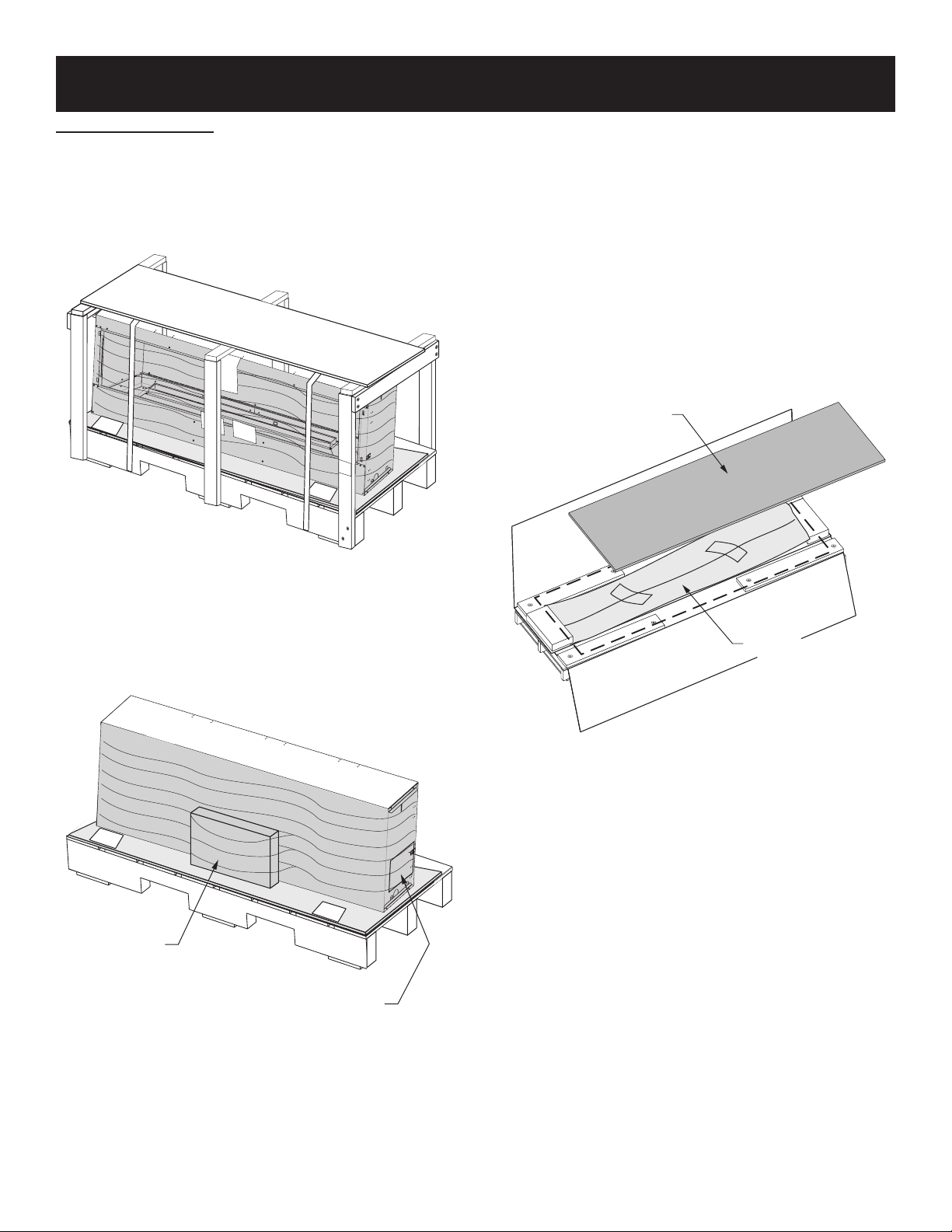
Unpacking the replace
1. 1. Retire los cuatro tornillos que sujetan la parte superior de
madera contrachapada a los soportes de las esquinas. Retire
la parte superior de madera contrachapada y deséchela.
2. Retire los dos tornillos que sujetan cada soporte de esquina
a la plataforma. Retire los soportes de esquina y deseche.
3. Corte la banda que asegura la chimenea a la plataforma.
Descartar las bandas.
NOTICE
SHEET
HANDLE WITH CARE
GLASS
GLASSLABEL
FRAGILELABEL
HANDLE WITH CARE
GLASS
CARTON LABEL
5. 5. Retire con cuidado el paquete del interior de la chimenea.
Este paquete contiene dos soportes de vidrio central y el
vidrio deflector del quemador. Coloque el paquete en un
lugar apartado para evitar dañar los componentes.
6. Levante la chimenea de la paleta y colóquela cerca del
sitio de instalación. Si la chimenea debe colocarse en un
extremo para que se pueda usar una carretilla para el
transporte, retire todos los componentes sueltos del interior
de la chimenea. Camión desde el extremo izquierdo (frente a
la abertura de la chimenea) solamente.
7. Retire el paquete de cartón superior y la placa
incombustible del palet.
8. Abra con cuidado el paquete de cartón que queda en la
plataforma. Este paquete contiene el deflector superior
interno opcional y la barrera de vidrio frontal. Coloque los
componentes en un lugar apartado para evitar dañarlos.
NON-COMBUSTIBLE
PANEL
Figure 1
4-Retire la envoltura de plástico que asegura el paquete de instrucciones y
la caja de hardware a la chimenea
HANDLE WITH CARE
GLASS
HANDLE WITH CARE
GLASS
HARDWARE
INSTRUCTION
PACKAGE
FRONT GLASS
Figure 3
Figure 2
Page 3
Page 4
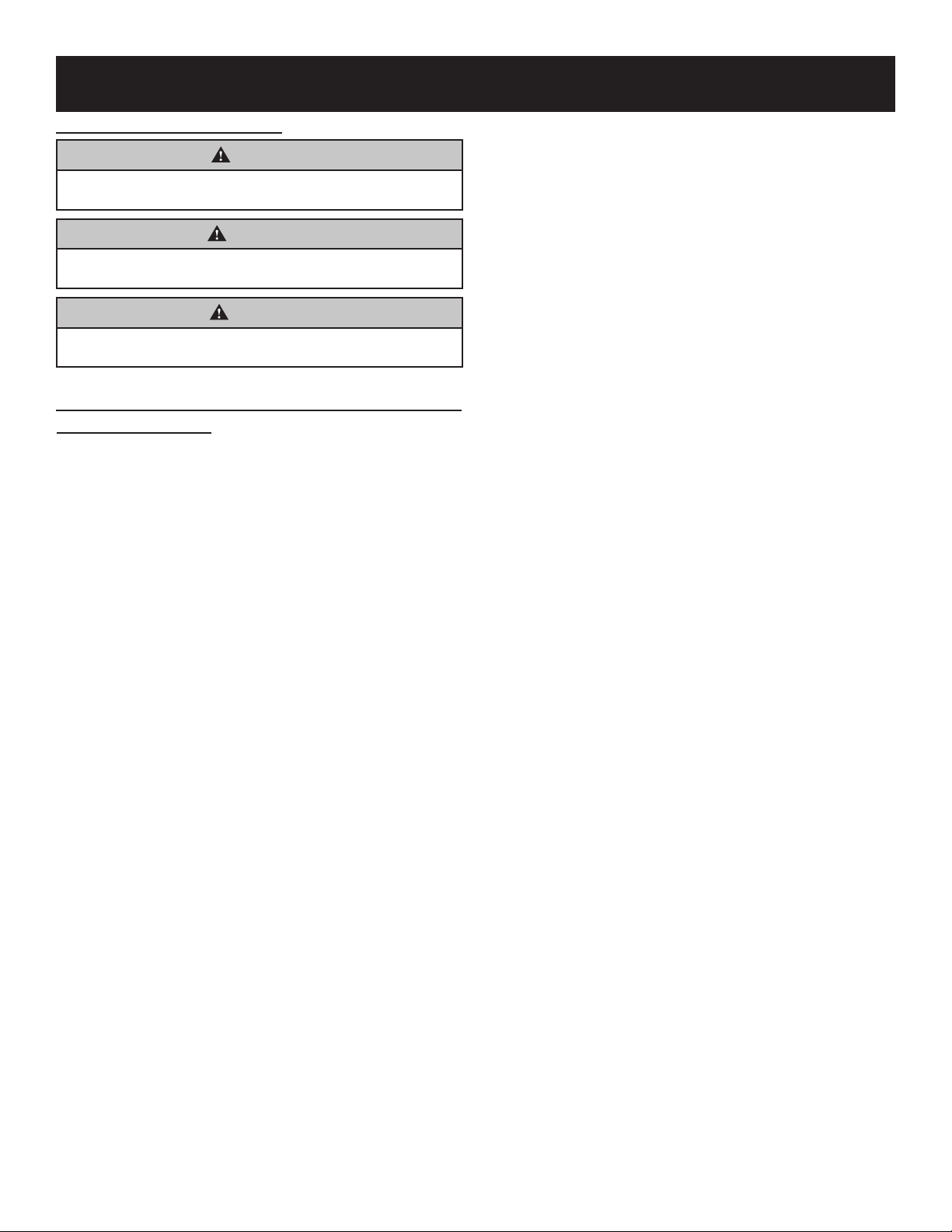
Antes de empezar
Ejemplos de advertencias y definiciones:
DANGER
Indica una situación peligrosa que, de no evitarse, ocasionará
la muerte o lesiones graves.
WARNING
Indica una situación peligrosa que, si no se evita, podría
provocar la muerte o lesiones graves.
CAUTION
Indica una situación peligrosa que, de no evitarse, podría
ocasionar lesiones leves o moderadas.
Notice: Addresses practices not related to personal injury.
Installation Information
1. 1. Lea la información de prevención de hollín en la página 7.
2. Lea la información de seguridad en las páginas 12 - 13.
3. Enmarque la apertura. Ver la página 17 y 26.
4. Instalar las líneas de gas. Ver la página 18.
5. Instale el cableado. Ver páginas 31 - 32.
6. Instala el sistema remoto. Ver página 37.
7. Encienda la chimenea y solucione los problemas.
Ver páginas 35 y 41 - 43.
Para obtener instrucciones detalladas sobre el funcionamiento de
8
Proflame - IP
9. . Para obtener instrucciones detalladas sobre los controles LED,
consulte la página 52.
10. Muestre al dueño de la casa cómo operar la chimenea,
ver la página 51 - 57.
11. Muestre al propietario cómo hacer el mantenimiento básico.
10. (Ver página 39)
Si la chimenea se instala directamente sobre alfombras,
baldosas u otro material combustible que no sea el piso de
madera, debe instalarse en un panel de metal o madera que se
extienda a todo lo ancho y la profundidad de la chimenea.
Esta chimenea está diseñada para instalarse en un cerramiento
sin espacio libre. Esto significa que el material combustible tal
como el armazón de madera puede entrar en contacto con los
espaciadores laterales y superiores del separador, y fijarse al
armazón combustible utilizando los soportes provistos.
Un deflector superior interno opcional se incluye con la
chimenea. Esto se puede usar para ayudar a distribuir el calor de
la chimenea de manera más uniforme a través de la abertura de
la chimenea. Esto no cambia los requisitos para el material no
combustible sobre la abertura de la chimenea.
Esta chimenea requiere que se instale una válvula de cierre de
gas fácilmente accesible en la línea de suministro de gas antes
de ingresar a la chimenea.
Determine lo siguiente antes de la instalación::
• • Cualquier accesorio deseado
• • Tubería de suministro de gas (entrada del lado izquierdo).
• • Conexiones eléctricas
• • Requisitos de suministro eléctrico para las luces (120V,
60Hz, 1 Amp) (entrada del lado izquierdo)
Se recomienda una selección de una válvula de cierre que
contenga una brida y una llave.
Opciones de acabado
Elige la opción de acabado.
Opción 1 - Limpiar cara: este tipo de instalación (página 22)
permitirá terminar alrededor de la abertura de la chimenea con
pintura a alta temperatura.
Opción 2: montaje empotrado: este tipo de instalación permitirá
usted debe aplicar baldosas, mármol, piedra u otro material no
combustible sobre la parte frontal del gabinete de la chimenea,
hasta la brida de apertura de la chimenea.
Consideraciones de instalación: pautas de instalación de la
chimenea Determine dónde instalar la chimenea. La chimenea se
puede montar en cualquiera de estas superficies:
1. 1. Una superficie plana, combustible o no
combustible.
2. Una plataforma elevada de material combustible
o no combustible.
Page 4 36776-4-0117
Page 5
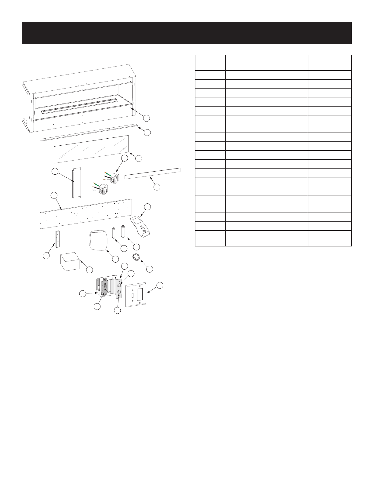
CARTON CONTENTS
CARTON CONTENTS
Items not shown to scale.
Index
Number
Description
Quantity
Supplied
1 Fireplace 1
2 Non-combustible Board - Top 1
3 Non-combustible Board - Side 2
4 Front Glass 1
5 Burner Glass 1
1
19
6 Bushing 3
7 Standoff Bracket 3
8 Receptical 2
9 Remote 1
8
4
10 AA Battery 4
11 AAA Battery 3
7
12 Hardware Pack 1
13 AC Adaptor 1
5
2
9
14 Wall Mounted Control Box 1
15 Remote Receiver 1
16 Button Switch 2
17 Mounting Bracket 1
18 Wall Plate 1
BAG
10
11
3
13
14
12
17
16
6
18
19
For hardware pack contents, see page 6.
See Parts Lists on pages 46 - 47 for ordering replacement parts.
Do not order batteries, bolts, screws, washers or nuts. They are
standard hardware items and can be purchased at any local
hardware store.
Inner Top Deector
(Optional Installation)
1
15
16
Page 5
Page 6
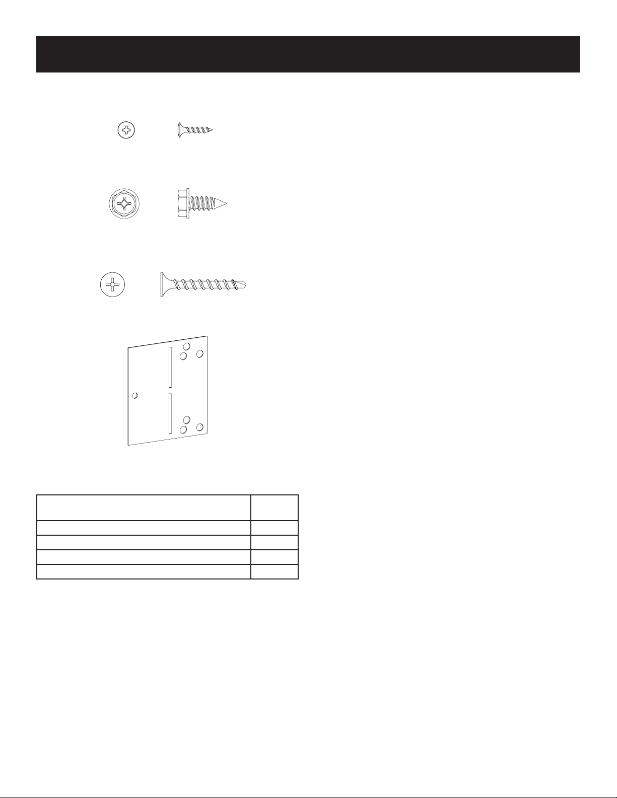
HARDWARE PACK
HARDWARE PACK CONTENTS
#4 X ½” STAINLESS PHILLIPS HEAD SCREW
#10 X ½” HEX HEAD SCREW
1” PHILLIPS SELF-DRILLING SCREW
NAILING FLANGES
(Not to scale)
Description
4 x 1/2 Phillips Pan Head Screw 4
10 X 1/2 Phillips Hex Head Screw 14
#8 x 1 inch Self-Drilling Drywall Screw 9
Nailing Flange 4
Vea las listas de piezas en la página 46 - 47 para pedir piezas
de repuesto. No pida pilas, pernos, tornillos, arandelas o
tuercas. Son artículos de hardware estándar y se pueden
comprar en cualquier ferretería local.
Quantity
Supplied
Page 6 36776-4-0117
Page 7
IMPORTANT SOOT PREVENTION STEPS
IMPORTANT NOTICE
INSTALLER - SERVICE PERSON - HOMEOWNER
SOOT MAY BE CREATED IF THE FOLLOWING DIRECTIONS ARE NOT FOLLOWED.
Una chimenea o un quemador sin ventilación extrae aire de la
habitación para soportar la combustión. Las partículas livianas
suspendidas en el aire, como el polvo, las fibras de la alfombra, las
velas o el humo del tabaco y el pelo de las mascotas, se atraerán
hacia la chimenea. Esto puede ocasionar que se acumule hollín en
los troncos, en las paredes de las chimeneas e incluso en las
paredes de la habitación. Para prevenir fallas y hollines, solicite a
su concesionario que inspeccione y limpie cada año, antes de la
temporada de calefacción. Si tiene mascotas o polvo excesivo,
puede ser necesaria una limpieza más frecuente. Ver la sección de
limpieza y servicio en este manual.
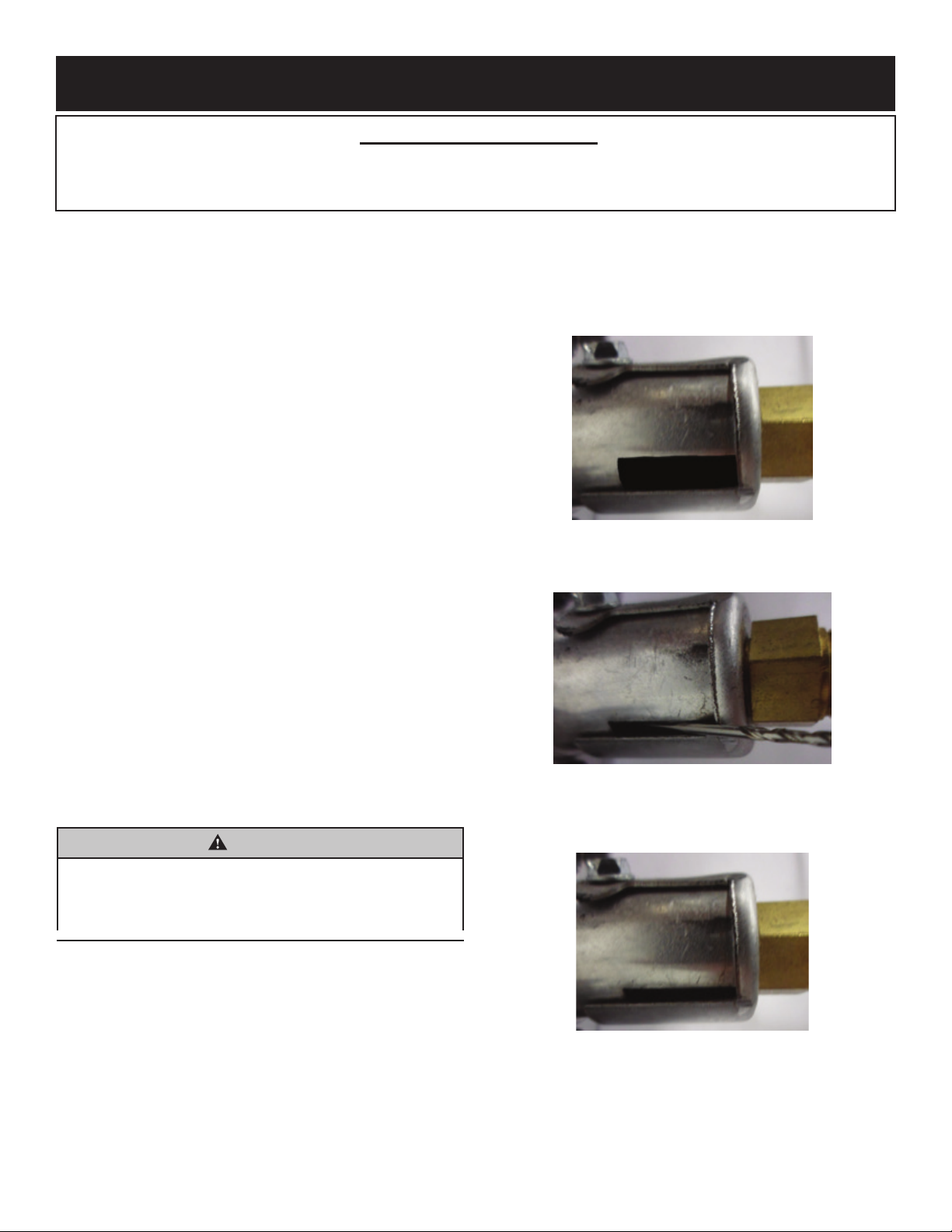
1. 1. Asegúrese de que el obturador de aire esté configurado según las
especificaciones. Vea las Figuras 4 a 6 en esta página y las Tablas 1 y 2 en
la página 8.
2. Asegúrese de que el quemador, el Venturi y el obturador de aire estén
libres de suciedad, pelusa, pelo de animal (es decir, gatos y perros) o
cualquier cosa que pueda bloquear el flujo de aire necesario. Consulte
Limpieza y servicio, página 40.
3. No coloque desechos, registros adicionales u otros artículos en el
quemador durante la operación.
4. No use ambientadores aromáticos o velas mientras la chimenea esté en
funcionamiento. Producen residuos que pueden causar hollín.
6. 6. No coloque papel de vidrio en los puertos del
quemador o del quemador. Los medios de vidrio solo
deben colocarse en el piso de la chimenea.
7. No use lana de roca (brasas) o roca de lava
9. Inspección anual y limpieza por parte de su distribuidor o un técnico calificado
Verifique que el obturador de aire tenga la configuración
correcta. Consulte las Tablas 1 y 2 en la página 8 para conocer
la configuración específica del obturador de aire para cada
modelo.
Modelos de gas LP: la configuración del obturador de aire debe
ser de 1/4 de pulgada.
(Ver Figuras 4, 5 y Tabla 1 en la página 8)
Figura 4 (se muestra una abertura de 1/4 de pulgada)
Pruebe el ajuste del obturador de aire con un objeto redondo como
una broca. El objeto apenas debe deslizarse entre la abertura. (Ver
figura 5)
se recomienda al técnico de servicio para evitar un mal
funcionamiento y / o hollín.
Instale registros opcionales de acuerdo con las instrucciones de
10.
instalación. Solo use Empire Logs especialmente diseñado para
esta chimenea.
Verifique que el tubo venturi no esté doblado o distorsionado. El
11.
orificio del quemador principal debe estar centrado en el tubo
Venturi para una combustión adecuada y para evitar que se
huelasooting.
WARNING
No permita que los ventiladores soplen directamente dentro o en la
chimenea. Evite cualquier corriente de aire que altere los patrones de
llamas del quemador. Evite cualquier corriente de aire que altere los
patrones de llamas del quemador. Preste especial atención a los
ventiladores de techo y extractores.
Figura 5 (se muestra una abertura de 1/16 de pulgada)
Modelos de gas NAT: la configuración del obturador de aire
debe ser de 1/16 de pulgada. (Consulte la Figura 6 y la
Tabla 2 en la página 8)
Figura 6
Figura 6 (se muestra una abertura de 1/16 de
pulgada)
Aviso: escudo de orificio eliminado para mayor claridad..
Page 7
Page 8
PRODUCT SPECIFICATIONS
VFLL60FP90LP VFLL60FP90LN VFLL72FP90LP VFLL72FP90LN
Input BTU/HR Maximum 38,500 40,000 38,500 40,000
Input BTU/HR Minimum 31,000 25,000 31,000 25,000
Orice 1.8mm #32 1.8mm #32
Notice: Air shutter settings are factory set and muay not be altered.
GAS SUPPLY PRESSURES (inches water column)
GAS TYPE MAXIMUM MINIMUM MANIFOLD
NAT 10.5 7.0 3.5
LP 13.0 11.0 10.0
Table 1 - Air Shutter Opening - Natural Gas Models
Model Air Shutter Opening
VFLL60FP90 1/16 inch
VFLL72FP90 1/16 inch
Table 2 - Air Shutter Opening - LP Gas Models
Model Air Shutter Opening
VFLL60FP90 1/4 inch
VFLL72FP90 1/4 inch
HOMEOWNER REFERENCE INFORMATION
We recommend that you record the following information about your replace.
Model Number: _____________________________ Date purchased: ________________________
Serial Number: _____________________________ Location of replace: _____________________
Dealer Name: ______________________________ Dealer Phone: _________________________
Notes: ______________________________________________________________________________
Page 8 36776-4-0117
Page 9

Required Accessories
ACCESSORIES
Part Number
VFLL60 VFLL72
DG1CLF DG1CLF Decorative Glass, Crushed - 1/4 inch Clear Frost (One kit per one square foot) Recommended
DG1BKP DG1BKP Decorative Glass, Crushed - 1/4 inch Black Polished (One kit per one square foot)
DG1BUC DG1BUC Decorative Glass, Crushed - 1/4 inch Blue Clear (One kit per one square foot)
DG1BCR DG1BCR Decorative Glass, Crushed - 1/4 inch Copper Reective (One kit per one square foot)
DG1BZR DG1BZR Decorative Glass, Crushed - 1/4 inch Bronze Reective (One kit per one square foot)
Notice: Decorative crushed glass is required for installation. Clear Frost Crushed Glass is recommended. Decorative Glass Droplets
cannot be substituted for crushed glass. One box of crushed glass covers 1 sq. ft. Glass colors may be mixed, however transparent
and translucent crushed glass will allow LEDs to better shine through.
Notice: Requires ve square feet for VFLL60, six square feet for VFLL72.
Notice: Never place media material on or next to the burner.
Description
Optional Accessories
Part Number
VFLL60 VFLL72
DFL601BL DFL721BL Decorative Front, Beveled, 1-inch, Black
DFL602BL DFL722BL Decorative Front, Beveled, 2-inch, Black
DFL602NB DFL722NB Decorative Front, Beveled, 3-inch, Brushed Nickel
VBP60LKR VBP72LKR Liner - Black Reective
VBP60LSS VBP72LSS Liner - Stainless Steel
LS60DF LS72DF Log Set
DG1AB DG1AB Decorative Glass Droplets - 1/2 inch Aqua Blue (One kit per one square foot)
DG1GC DG1GC Decorative Glass Droplets - 1/2 inch Glacier Ice (One kit per one square foot)
DG1SL DG1SL Decorative Glass Droplets - 1/2 inch Sangria Luster (One kit per one square foot)
DG1NXS DG1NXS Decorative Glass Drops - 1 inch Onyx Solid (One kit per one square foot)
DG1TZC DG1TZC Decorative Glass Drop - 1 inch Topaz Clear (One kit per one square foot)
DRFPA DRFPA Decorative Rock, Ceramic Fiber - Pebble (One kit per 1/2 square foot)
Description
Notice: If installing a decorative front, an offset between the nishing materials and replace opening is required. Refer to page 25 and
29 as well as the installation instructions provided with the decorative front for more information.
Page 9
Page 10
INTRODUCTION
Instructions to Installer
1. 1. Deje el manual de instrucciones con el propietario después de la
instalación.
2. Haga que el dueño complete y envíe por correo la Tarjeta de registro
del producto que se suministra con la chimenea sin ventilación.
3. Complete la información de referencia del propietario en la página 8.
4. Muestre al propietario cómo iniciar y operar la chimenea sin
ventilación.
5. Mostrar el mantenimiento básico del propietario
Siempre consulte a su Departamento de Construcción local con respecto a
las regulaciones, códigos u ordenanzas que se aplican a la instalación de
una chimenea sin ventilación.
Esta chimenea se puede instalar en una casa fabricada (móvil) en el
mercado de accesorios *, donde no esté prohibida por los códigos estatales
o locales.
* Mercado de accesorios: finalización de la venta, no con fines de reventa,
Desde el fabricante.
WARNING
Este aparato está equipado para gas natural o propano. La
conversión de campo no está permitida.
WARNING
Cualquier cambio en esta chimenea o sus controles puede ser
peligroso. La instalación o el uso incorrectos de la chimenea pueden
causar lesiones graves o la muerte por fuego, quemaduras, explosión
o envenenamiento por monóxido de carbono..
Esta chimenea está diseñada para calefacción suplementaria.
Cualquier alteración del diseño original, instalado de manera
diferente a la mostrada en estas instrucciones o uso con un tipo
de gas que no se muestra en la placa de características es
responsabilidad de la persona y la empresa que realiza el
cambio.
Importante
Toda la correspondencia debe referirse al número de modelo
completo, al número de serie y al tipo de gas. (Vea la página 8)
Durante la fabricación, esta chimenea se trata con aceites,
películas y agentes adhesivos. Estos no son dañinos, pero
pueden producir humo y olor ya que se queman durante la
operación inicial. Esto es normal. Abra la ventana para ventilar
cualquier humo u olor
Instalación en alfombras y azulejos
Si esta chimenea se instala directamente sobre alfombras,
azulejos u otros materiales combustibles que no sean pisos de
madera, la chimenea debe instalarse sobre un panel de metal o
madera que se extienda a todo lo ancho y la profundidad de la
chimenea.
Agencia de instalación calificada
La instalación y el reemplazo de tuberías de gas, equipos o
accesorios de utilización de gas y la reparación y el
mantenimiento del equipo deben ser realizados únicamente por
una agencia calificada. El término agencia calificada significa
cualquier individuo, empresa, corporación o compañía que en
persona oa través de un representante participe y sea
responsable de (a) la instalación o reemplazo de la tubería de
gas o (b) la conexión, instalación, reparación o servicio de
equipos, que tenga experiencia en dicho trabajo, que esté
familiarizado con todas las precauciones requeridas y que haya
cumplido con todos los requisitos de la autoridad competente..
Mancomunidad de Massachusetts: la instalación debe
realizarla un fontanero o instalador de gas con licencia en la
Mancomunidad de Massachusetts.
Vendedores de propano no propagado o suplementos de gas
naturall fireplaces proporcionará a cada comprador una copia
de 527 CMR 30 al momento de la venta de la unidad.
En la Mancomunidad de Massachusetts, se prohíbe el uso de
propano y calentadores de aire a gas natural en dormitorios y
baños.
La instalación debe cumplir con los códigos locales o, a falta de
códigos locales, con el Código Nacional de Gas Combustible,
ANSI Z223.1. * / NFPA 54.
* Disponible desde el American National Standards Institute,
Inc.
1430 Broadway, Nueva York, N.Y. 10018.
Page 10 36776-4-0117
Page 11

INFORMACION IMPORTANTE
WARNING
Si no se mantienen las aberturas de aire primario del quemador (es)
limpio (s), se pueden producir hollines y daños a la propiedad..
For the Installer
• La instalación y reparación debe realizarla un técnico
calificado. La chimenea debe ser inspeccionada antes de su
uso y al menos una vez al año por un técnico calificado. Es
posible que se requiera una limpieza más frecuente debido
a la pelusa excesiva de alfombras, material de cama, etc.
Es imperativo que los compartimentos de control, los
quemadores y los conductos de aire circulante de la
chimenea se mantengan limpios. Mantenga limpio el
quemador y el compartimento de control.
• • Una chimenea de la sala sin ventilación que tenga una
clasificación de entrada de más de 6.000 Btu por hora no se
instalará en un baño
• • Una chimenea de la habitación sin ventilación que tenga
una clasificación de entrada de más de 10,000 Btu por hora
no se debe instalar en un dormitorio o baño.
• • Use materiales no combustibles donde se indique para la
instalación de la chimenea. El material no combustible no se
enciende ni se quema como resultado del uso de la
chimenea. Estos incluyen metal, ladrillo, cerámica,
hormigón, pizarra, vidrio y yeso. Los adhesivos deben estar
clasificados para altas temperaturas. Todos los sujetadores
mecánicos utilizados para instalar el material también deben
ser no combustibles, incluidos los anclajes de pared y los
separadores de azulejos. Los materiales que superan la
prueba ASTM E 136 (Método de prueba estándar para el
comportamiento de los materiales en un horno de tubos
verticales a 750 ° C) se consideran no combustibles.
• • Instale la chimenea fuera del tráfico del hogar y lejos de
muebles y cortinas. Las altas temperaturas producidas por
la chimenea crean un riesgo de ignición..
Para el propietario
• • No permita que materiales combustibles adyacentes o en
c
ontacto con la chimenea. Los materiales combustibles
incluyen madera, papel comprimido, fibras vegetales u otros
materiales que se quemarán. Estos materiales se consideran
combustibles incluso cuando se tratan con productos químicos
ignífugos.
• • Alerte a los niños y adultos sobre los peligros de las altas
temperaturas de la superficie. Adviértales que se mantengan
alejados para evitar quemaduras y el encendido de la ropa.
• • Supervise a los niños cuando están en la misma habitación
que la chimenea.
• • No coloque ropa u otro material inflamable sobre o cerca de
la chimenea.
• • Se debe reemplazar cualquier pantalla o protector de
seguridad para dar servicio a la chimenea antes de operar la
chimenea.
• • Mantenga el área de la chimenea despejada y libre de
materiales combustibles, gasolina y otros vapores y líquidos
inflamables.
• • No use esta chimenea si alguna parte ha estado bajo el
agua. Llame inmediatamente a un técnico de servicio
calificado para inspeccionar la chimenea y reemplazar
cualquier parte del sistema de control y cualquier control de
gas que haya estado bajo el agua.
• • Opere la chimenea con todos los paneles de vidrio en su
lugar.
• • No coloque brasas (lana de roca) en esta chimenea.
• • No coloque piedras de lava en esta chimenea.
Page 11
Page 12
INFORMACION DE SEGURIDAD IMPORTANTE
WARNING
Cuando se usa s
ventilación, el artefacto puede emitir MONÓXIDO DE
CARBONO, un gas venenoso e inodoro.
No instale el aparato hasta que todas las disposiciones
necesarias estén hechas para la combustión y el aire de
ventilación. Consulte las instrucciones escritas proporcionadas
con el aparato para obtener información sobre la combustión y el
aire de ventilación. En ausencia de instrucciones, consulte el
Código Nacional de Gas Combustible, ANSI Z223.1 / NFPA 54,
Aire para Combustión y Ventilación, o los códigos locales
aplicables..
E
ste electrodoméstico está equipado con un SISTEMA DE SEGURIDAD
DE LUZ PILOTO diseñado para apagar el artefacto si no hay suficiente
aire fresco disponible.
El sistema de seguridad de luz piloto detecta el agotamiento de oxígeno
en su ubicación. Si esta chimenea se instala en una estructura con una
gran dimensión vertical, existe la posibilidad de que el suministro de
oxígeno en los niveles superiores sea menor que en la chimenea. En este
tipo de aplicación, un ventilador para hacer circular la estructura de aire
minimizará este efecto. El uso de este ventilador también mejorará el
nivel de comodidad en la estructura. Cuando se usa un ventilador para
hacer circular el aire, debe ubicarse de modo que el flujo de aire no esté
dirigido hacia el quemador..
NO TAMPER CON EL SISTEMA DE SEGURIDAD DE LUZ PILOTO!
¡
Si la chimenea se apaga, no vuelva a encenderla hasta que
proporcione aire fresco.
Si la chimenea se sigue apagando, haga que reparen. Mantenga limpio
el quemador y el compartimento de control. Consulte las instrucciones
de instalación y funcionamiento que acompañan al calentador.
in una combustión adecuada y aire de
WARNING
CARBON MONOXIDE POISONING MAY
LEAD TO DEATH.
Los primeros signos de intox
parecen a la gripe, con dolor de cabeza, mareos y / o náuseas. Si
tiene estos signos, es posible que la chimenea no funcione
correctamente. ¡Obtén aire fresco a la vez! Haga reparar la chimenea.
Algunas personas (mujeres embarazadas, personas con
enfermedades cardíacas o pulmonares, anemia, personas bajo la
influencia del alcohol, personas que viven en grandes alturas) se ven
más afectadas por el monóxido de carbono que otras persona
icación por monóxido de carbono se
DANGER
El instalador de este producto es responsable de verificar la posición
correcta del obturador de aire y ajustarlo si es necesario. Si no se
ajusta a la abertura adecuada, un incendio, explosión o producción
de monóxido de carbono puede causar daños a la propiedad,
lesiones personales o la muerte
DANGER
El instalador de este producto es responsable de probar todas las
conexiones en busca de fugas de gas. Una fuga de gas creará una
situación donde un incendio, explosión o producción de monóxido de
carbono puede resultar en daños a la propiedad, lesiones personales
o pérdida de vidas.
WARNING
No utilice un inserto de soplador, inserto de intercambiador de calor u
otro accesorio no aprobado para su uso con este calentador. El uso
de accesorios no probados y aprobados para su uso con esta
chimenea creará una situación donde un incendio, explosión o
producción de monóxido de carbono puede causar daños a la
propiedad, lesiones personales o la muerte..
WARNING
Esta chimenea necesita aire fresco para que la ventilación funcione
correctamente. Un suministro de aire inadecuado puede crear una
situación donde un incendio, explosión o producción de monóxido de
carbono puede resultar en daños a la propiedad, lesiones personales
o pérdida de vidas. Esta chimenea tiene un ODS (sensor de
agotamiento de oxígeno) que apagará la chimenea si no hay suficiente
aire fresco disponible. Ver la sección de solución de problemas en las
instrucciones
WARNING
No opere esta chimenea a menos que todos los componentes,
incluidos los quemadores y los controles, estén en buenas
condiciones de funcionamiento. Nunca opere esta chimenea si algún
registro o rama opcional está roto o fuera de su posición prevista.
Consulte las instrucciones de ubicación del conjunto de registros para
el registro correcto y el posicionamiento de la ramificación. Los
componentes de repuesto están disponibles a través de su
distribuidor local, como se indica en la sección Cómo pedir piezas de
reparación del manual de la chimenea..
Page 12 36776-4-0117
Page 13

INFORMACIÓN DE SEGURIDAD PARA USUARIOS DE Gas LP
El propano (gas LP) es un gas inflamable que puede causar
incendios y explosiones. En su estado natural, el propano es
inodoro e incoloro. Es posible que no conozca todas las
precauciones de seguridad siguientes que pueden protegerlo a
usted y a su familia de un accidente. Léelos detenidamente ahora,
luego revíselos punto por punto con los miembros de su hogar.
Algún día, cuando no haya un minuto para perder, la seguridad de
todos dependerá de saber exactamente qué hacer. Si, después de
leer la siguiente información, siente que todavía necesita más
información, comuníquese con su proveedor de gas.
Orden de advertencia de gas LP
Si ocurre una fuga de gas, debe poder oler el gas debido
al olor introducido en el Gas LP.
¡Esa es tu señal para entrar en acción inmediata!!
• • No opere interruptores eléctricos, fósforos ligeros ni use su teléfono.
No hagas nada que pueda encender el gas.
• • Saque a todos del edificio, vehículo, remolque o área. Hazlo
INMEDIATAMENTE.
• • Cierre todas las válvulas de suministro de tanque de combustible o
cilindro.
• • El gas LP es más pesado que el aire y puede depositarse en áreas
bajas como los sótanos. Cuando tenga motivos para sospechar una
fuga de gas, manténgase alejado de los sótanos y otras áreas bajas.
Permanezca afuera hasta que los bomberos declaren que están a
salvo.
• • Use el teléfono de su vecino y llame a un técnico de LP capacitado
y al departamento de bomberos. Aunque no continúe oliendo a gas,
no vuelva a encender el gas. No vuelva a ingresar al edificio,
vehículo, remolque o área.
• • Finalmente, permita que el hombre del servicio y los bomberos
comprueben si hay escapes de gas. Haga que ventilen el área antes
de regresar. Las personas del servicio de Gas LP debidamente
capacitadas deben reparar la fuga, luego verificar y volver a
encender la chimenea de gas por usted.
No se detectó ningún olor - Se desvaneció el olorAlgunas personas no
pueden oler bien. Algunas personas no pueden oler el olor del químico
puesto en el gas. Debe averiguar si puede oler el olor en propano. Fumar
puede disminuir su capacidad de oler. Estar cerca de un olor por un tiempo
puede afectar su sensibilidad o capacidad de detectar ese olor. A veces,
otros olores en el área enmascaran el olor a gas. La gente puede no oler el
olor a gas o sus mentes están en otra cosa. Pensar en oler un olor a gas
puede hacer que sea más fácil oler.El odorante en Gas LP es incoloro y
puede desaparecer en algunas circunstancias. Por ejemplo, si hay una fuga
subterránea, el movimiento del gas a través del suelo puede filtrar el
odorizante. Los aromatizantes en Gas LP también están sujetos a la
oxidación. Este desvanecimiento puede ocurrir si hay óxido dentro del
tanque de almacenamiento o en las tuberías de gas de hierro.El odorante
en el gas escapado puede adsorberse o absorberseo en paredes,
mampostería y otros materiales y telas enun cuarto. Eso eliminará parte del
olor del gas, reduciendo su intensidad de olor.El gas LP puede estratificarse
en un área cerrada, y la intensidad del olor puede variar a diferentes
niveles. Como es más pesado que el aire, puede haber más olor en niveles
más bajos. Siempre sea sensible al menor olor a gas. Si detecta algún olor,
trátelo como una fuga seria. Inmediatamente entre en acción como se
indicóanteriormenter.
Algunos punto para recordar
• Aprenda a reconocer el olor del Gas LP. Su distribuidor local de gas
LP puede darle un folleto Scratch and Sniff. Úselo para descubrir
cómo huele el olor a propano. Si sospecha que su gas LP tiene un
olor débil o anormal, llame a su distribuidor de gas LP.
• • Si no está calificado, no encienda las luces piloto, realice tareas de
servicio o realice ajustes en las chimeneas del sistema de Gas LP.
Si está calificado, piense de forma consciente en el olor a gas LP
antes y mientras enciende las luces piloto o realizando servicio o
haciendo ajustes.
• • A veces, un sótano o una casa cerrada tiene un olor a humedad
que puede tapar el olor a gas LP. No intente encender luces piloto,
realizar servicio o realizar ajustes en un área donde las condiciones
sean tales que no pueda detectar el olor si se ha producido una fuga
de gas LP.
• • Se puede desvanecer el olor debido a la oxidación por oxidación o
adsorción en paredes de cilindros y tanques nuevos. Por lo tanto, las
personas deben estar particularmente alerta y ser cuidadosas
cuando se colocan en servicio tanques o cilindros nuevos. El
desvanecimiento del olor puede ocurrir en tanques nuevos, o en
tanques viejos reinstalados, si se llenan y se dejan fraguar
demasiado tiempo antes de volver a llenarlos. Los cilindros y
tanques que han estado fuera de servicio por un tiempo pueden
desarrollar óxido interno que causará la desaparición del olor. Si se
sospecha que existen tales condiciones, es aconsejable realizar una
prueba de aspiración periódica del gas. Si tiene alguna pregunta
sobre el olor a gas, llame a su distribuidor de gas LP. Una prueba de
aspiración periódica del gas LP es una buena medida de seguridad
bajo cualquier condición.
Si, en cualquier momento, no huele el odorante de Gas LP y
•
cree que debería, suponga que tiene una fuga. Luego tome
la misma acción inmediata recomendada anteriormente para
la ocasión cuando detecte el gas LP odorizado.
•
Si experimenta una salida de gas completa (el contenedor
no está bajo presión de vapor), apague la válvula del tanque
inmediatamente. Si la válvula del contenedor se deja
encendida, el contenedor puede aspirar algo de aire a través
de aberturas tales como orificios de luz piloto. Si esto ocurre,
podría producirse una nueva oxidación interna. Si la válvula
se deja abierta, entonces trate el recipiente como un tanque
nuevo. Siempre asegúrese de que su contenedor esté bajo
presión de vapor, apáguelo en el contenedor antes de que
se vacíe por completo o vuelva a llenarlo antes de que esté
completamente vacío.
36776-4-0117
Page 13
Page 14

DIRECTRICES DE INSTALACIÓN IMPORTANTES
Flujo de aire primario adecuado en el quemadorPara un
funcionamiento correcto del quemador y la apariencia de la
llama, el flujo de aire primario en el tubo venturi, ubicado en la
entrada de gas del quemador, no debe reducirse. Este flujo de
aire se reduce si se acumula suciedad, pelusa u otras
obstrucciones alrededor o dentro del venturi. Cualquier
obstrucción en el área del tubo venturi debe ser eliminada. El
flujo de aire en el Venturi también se reduce si el orificio de gas
no está centrado en la entrada Venturi y / o no está alineado con
el Venturi. Cualquier desalineación del orificio del quemador se
puede corregir doblando la tapa del obturador que sujeta el
orificio a la entrada del tubo Venturi.
Ventiladores de techo, ventiladores portátiles o registros
instalados cerca del aire frío
Los ventiladores de techo o ventiladores de tipo piso oscilante
deben monitorearse durante la operación de una chimenea sin
ventilación. Si el aire sopla directamente en la llama, causando
que rompa la llama, se debe apagar o redirigir. Los ventiladores
de techo podrían invertirse para posiblemente eliminar el
impacto de la llama, y el ventilador de piso debería ser redirigido.
Al momento de la instalación, tenga en cuenta el retorno de aire
frío o los respiraderos en las proximidades de la chimenea.
Cualquier corriente de aire creada alrededor de una chimenea
sin ventilación puede hacer que la llama incida sobre los troncos
o los medios decorativos y cree una situación de hollín.
Consideraciones de televisión
Instalar un televisor sobre una chimenea se ha vuelto cada vez
más popular; sin embargo, el área sobre cualquier chimenea se
calienta y la mayoría de los fabricantes de televisores
recomiendan no colocar sus productos cerca de una fuente de
calor.
Si instala un televisor sobre esta chimenea, Empire Comfort
Systems no acepta responsabilidad por daños o lesiones. Siga
las instrucciones de instalación del fabricante de la televisión,
incluidas las recomendaciones sobre la proximidad a las fuentes
de calor.
Si tiene un televisor encima de la chimenea, apague la chimenea
y deje que se enfríe por completo antes de reparar o tocar
cualquier botón del televisor.
VAPOR DE AGUA: UN SUBPRODUCTO DE CALENTADORES DE HABITACIONES SIN VENTILACIÓ
El vapor de agua es un subproducto de la combustión de gas.
Un calentador de sala sin ventilación produce aproximadamente
una onza (30 ml) de agua por cada 1,000 BTU (.3 KW) de
entrada de gas por hora.
Los calentadores de habitación sin ventilación se recomiendan
como calor suplementario (una habitación) en lugar de una
fuente de calor primaria (una casa completa). En la mayoría de
las aplicaciones de calor suplementario, el vapor de agua no
crea un problema. En la mayoría de las aplicaciones, el vapor de
agua mejora la atmósfera de baja humedad que se experimenta
durante el clima frío.
Los siguientes pasos ayudarán a garantizar que el vapor de
agua no se convierta en un problema.
1. Asegúrese de que el calentador tenga el tamaño adecuado
para la aplicación, incluido un amplio aire de combustión y
aire de circulación.
2. Si se experimenta una alta humedad, un deshumidificador
ayudará a reducir el contenido de vapor de agua del aire.
3. No use un calentador de ambiente sin ventilación como la
fuente principal de calor.
Page 14 36776-4-0117
Page 15

DISPOSICIONES PARA UNA COMBUSTIÓN ADECUADA Y AIRE DE VENTILACIÓN
Este calentador no se debe instalar en un espacio confinado a menos que se
proporcionen las disposiciones para una combustión adecuada y aire de ventilación.
El Código Nacional de Gas Combustible define un espacio confinado como un
espacio cuyo volumen es menor a 50 pies cúbicos por 1,000 Btu por hora (4.8m3 por
kw) de la clasificación de entrada agregada de todos los artefactos instalados en ese
espacio y un espacio no confinado como espacio cuyo volumen no es inferior a 50
pies cúbicos por 1,000 Btu por hora (4.8 m3 por kw) de la clasificación de entrada
agregada de todos los artefactos instalados en ese espacio. Las habitaciones que se
comunican directamente con el espacio en el que se instalan los artefactos, a través
de aberturas no provistas de puertas, se consideran parte del espacio no confinado.
Construcción inusualmente apretada
El aire que gotea alrededor de las puertas y ventanas puede proporcionar suficiente
aire fresco para la combustión y la ventilación. Sin embargo, en edificios de
construcción inusualmente apretada, debe proporcionar aire fresco adicional.
Unusually tight construction is dened as construction where:
a. a. Las paredes y los techos expuestos a la atmósfera exterior tienen
un retardador de vapor de agua continuo con una calificación de
una permanente o inferior con aberturas selladas o selladas, y
b. segundo. Weatherstripping se ha agregado en ventanas y puertas
que se pueden abrir, y
c. do. Los selladores o selladores se aplican a áreas tales como juntas
alrededor de ventanas y marcos de puertas, entre placas de piso y
pisos, entre juntas de pared y techo, entre paneles de pared, en
penetraciones para tuberías, líneas eléctricas y de gas, y en otras
Ejemplo de habitación grande con 1/2 divisor de pared.
Figura 7
La siguiente fórmula se puede usar para determinar la calificación
máxima del calentador según la definición de espacio no confinado
aberturas.
Si su hogar cumple con los tres criterios anteriores, debe
proporcionar aire fresco adicional.
WARNING
Si el área en la que se puede operar el calentador es más pequeña
que la definida como espacio no confinado o si el edificio tiene una
construcción inusualmente hermética, proporcione una combustión y
aire de ventilación adecuados mediante uno de los métodos descritos
en el Código Nacional de Gas Combustible, ANSI Z223 .1 / NFPA 54,
Aire para combustión y ventilación, o códigos locales aplicables.
Si el área en la que se puede operar el calentador es más pequeña
que la definida como espacio no confinado, proporcione una
combustión y aire de ventilación adecuados mediante uno de los
métodos descritos en el Código Nacional de Gas Combustible, ANSI
Z223.1, NFPA54.
Cumpla con todos los códigos, o en su defecto, con la última edición
del CÓDIGO NACIONAL DE GASOLINA DE COMBUSTIBLE ANSI
Z223.1 / NFPA54 que se puede obtener de:
American National Standards Institute National Fire Protection
Association, Inc..
FIREPLACE
H
W
Btu/Hr =
DIVIDER
(L
+ L2)FT x (W)FT x (H)FT
1
50
L
2
L
1
x 1000
11 West 42nd St. Batterymarch Park
New York, NY 10018 Quincy, MA 02269
Page 15
Page 16
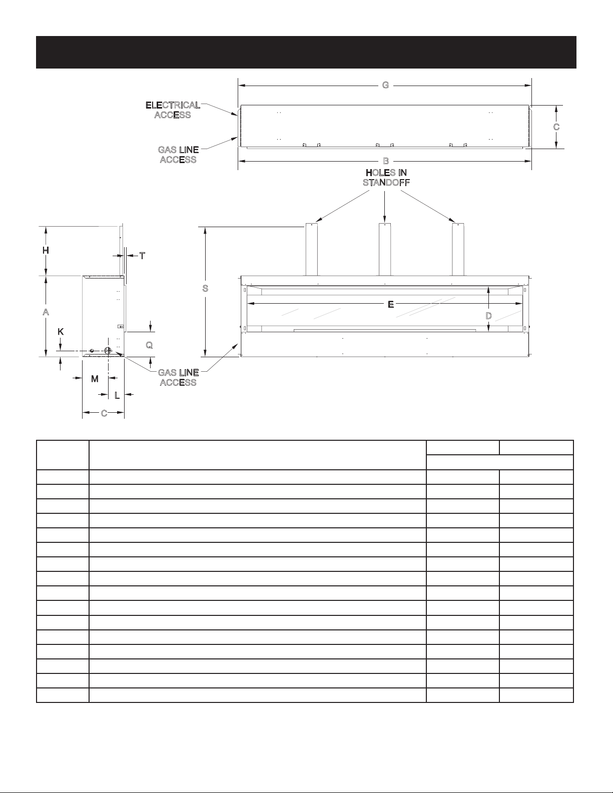
DIMENSIONES DE CHIMENEA
G
ELECTRICAL
ACCESS
C
GAS LINE
ACCESS
H
T
S
A
K
Q
B
HOLES IN
STANDOFF
E
D
M
L
C
INDEX
LETTER
A The maximum height of rebox face (excluding standoffs) 22-1/4 22-1/4
B The maximum width of the rebox face (excluding nailing anges) 64-3/4 76-3/4
C The maximum depth of the rebox 11-1/4 11-1/4
D The height of the rebox opening 12-1/8 12-1/8
E The width of the rebox opening 60 72
F The interior depth of the rebox (not shown) 10-1/2 10-1/2
G The rear exterior width of the rebox (not shown) 64-3/4 76-3/4
H The height to the rebox standoffs 18-15/16 18-15/16
K Height from the bottom of the rebox to the gas line opening 1-5/8 1-5/8
L Depth from the front of the rebox to gas line opening 4-5/16 4-5/16
M Depth from rear of rebox to gas line opening 6-7/8 6-7/8
N Glass height (not shown) 8 8
O Glass width (not shown) 61-3/8 73-3/8
Q Distance from replace bottom to replace opening 7-1/2 7-1/2
S Overall height to header 41-1/8 41-1/8
T Opening Lip 1/2 1/2
GAS LINE
ACCESS
DIMENSION DESCRIPTION
VFLL60FP VFLL72FP
Dimensions in Inches
Page 16 36776-4-0117
Page 17
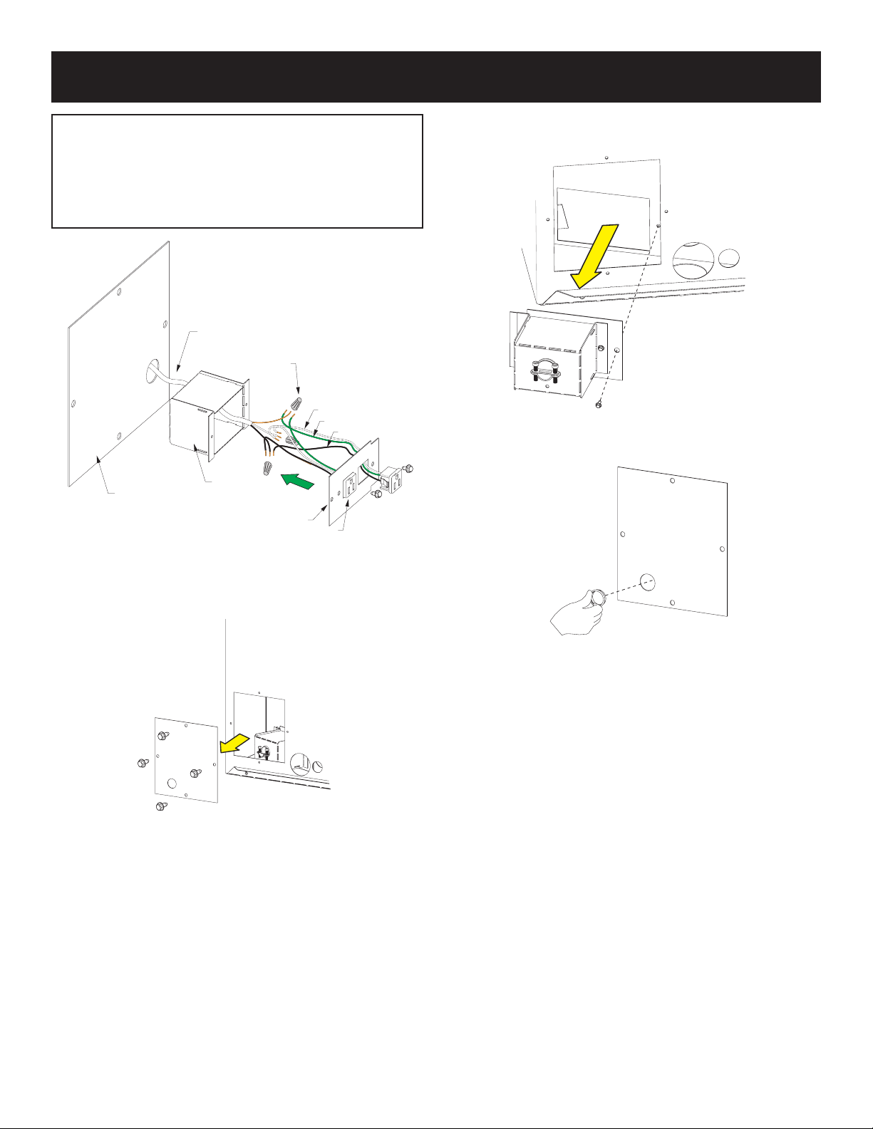
INSTALACIÓN DEL CABLEADO DE LA CAJA DE CONEXIÓN
Todo el cableado debe realizarlo un electricista calificado y deberá
cumplir con todos los códigos de construcción locales, urbanos y
estatales. Antes de hacer la conexión eléctrica, asegúrese de que la
fuente de alimentación principal esté desconectada. La chimenea,
cuando está instalada, debe estar conectada a tierra de acuerdo con los
códigos locales o, a falta de códigos locales, con el Código Eléctrico
Nacional ANSI / NFPA 70 (última edición)
120V POWER
SUPPLY
WIRE NUT
WHITE
GROUND
BLACK
JUNCTION
ELECTRICAL
COVER
PLATE
BOX
COVER PLATE
PUSH-IN
RECEPTICLE
2. Retire el conjunto de la caja de conexiones del
interior del
chimenea vea Figure 10.
Figure 10
3. Instale un casquillo de plástico en el panel de acceso eléctrico.
vea Figure 11.
Figure 8
1Retire el panel de la cubierta de acceso eléctrico del extremo izquierdo
de la chimenea Ver la Figura 9..
Retire la tapa de la caja de conexiones. Ejecute 14/2 NM-B con tierra
4.
o 12/2 NM-B con cable de tierra a través del panel de acceso
eléctrico en la caja de conexiones. Asegure el cableado con el
conector de cable según sea necesario e instale los dos
receptáculos como se muestra en la Figura 8. Conecte los cables
negros con una tuerca de cable y los cables blancos con una tuerca
de cable. Asegure el cable de tierra entrante y los cables de tierra
del receptáculo verde debajo del tornillo verde de conexión a tierra
provisto en la caja de conexiones. Vuelva a instalar la tapa de la caja
de conexiones.
Vuelva a instalar la caja de conexiones en la esquina inferior
5.
Figura 9
Instalación del cableado de la caja de conexiones
Una caja de conexiones instalada de fábrica está ubicada en la
esquina inferior izquierda dentro de la cavidad inferior de la
cámara de combustión. Los requisitos eléctricos de 120V
izquierda de la cavidad de la cámara de combustión usando los
tornillos que retiró en el paso 2. Consulte la Figura 11..
6 Vuelva a instalar el panel de acceso eléctrico con
los tornillos
sugeridos incluyen la instalación del receptáculo eléctrico en la
caja de conexiones ubicada en la esquina inferior izquierda
dentro de la cavidad inferior de la cámara de combustión. Esto
eliminado en el paso 1. Ver figura 9
se usará para enchufar el adaptador de CA / CC que
proporciona energía al sistema de válvula electrónica.
Mueva la chimenea a su ubicación final o cerca de ella antes de
instalar un cable eléctrico o conectar líneas de gas.
Figure 11
Page 17
Page 18
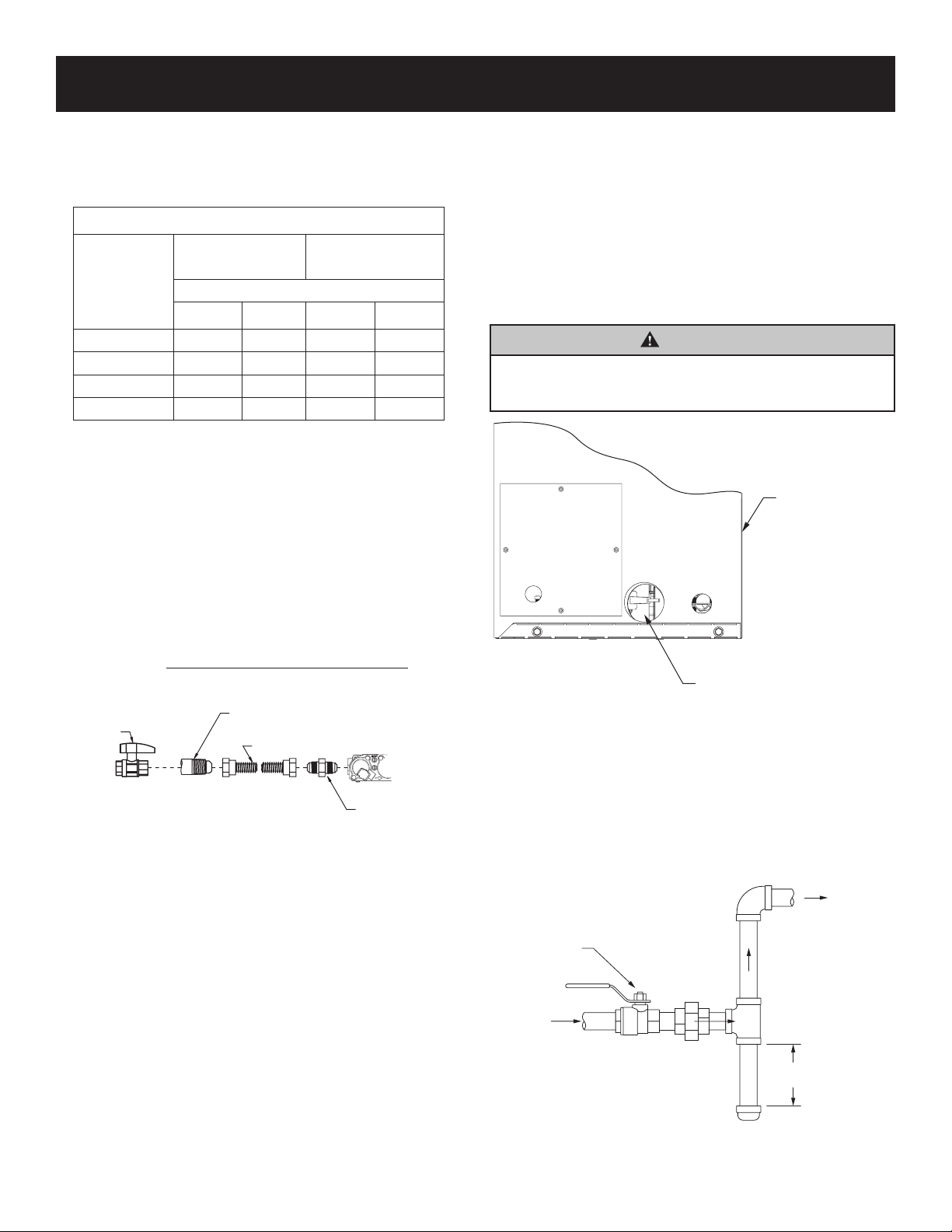
SUMINISTRO DE GAS
GAS SUPPL
CONTROL
FLEXIBLE GAS LINE CONNECTION
El gasoducto puede introducirse por el lado izquierdo de la chimenea.
La chimenea tiene un Flexline ubicado en el lado izquierdo cuando se
mira hacia la chimenea. Vea las Figuras 12 y 13. Consulte el Código
de Gas Combustible Nacional actual, ANSI Z223.1 CAN / CGA-B149
(.1 o .2) código de instalación
Recommended Gas Pipe Diameter
Pipe Length
(Dimensions
in feet)
Schedule 40 Pipe
Inside Diameter
(Dimensions in Inches)
Tubing, Type L
Outside Diameter
Nat. L.P. Nat. L.P.
0-10 1/2 3/8 1/2 3/8
11-40 1/2 1/2 5/8 1/2
41-100 1/2 1/2 3/4 1/2
101-150 3/4 1/2 7/8 3/4
Precaución: Nunca use tubos de plástico. Verifique para confirmar
si sus códigos locales permiten tubos de cobre o galvanizados.
Aviso: dado que algunos municipios tienen códigos locales
adicionales, siempre es mejor consultar su autoridad local y el código de
instalación.
Se recomienda el uso de los siguientes conectores de gas:
- ANSI Z21.24 Conectores de chimenea de metal corrugado
Tubos y accesorios
- ANSI Z21.45 Conectores de chimenea flexibles ensamblados de
Distinto de la construcción completamente metálica
Los conectores anteriores se pueden usar si lo acepta la autoridad
competente. El estado de Massachusetts requiere que un conector de
chimenea flexible no pueda exceder los tres pies de longitud..
AVISO: Los controles de gas están equipados con un punto de prueba
de presión de tipo tornillo capturado. No es necesario proporcionar un
punto de prueba de 1/8-pulgada arriba del control.
Cuando utilice cobre o conector flexible, use solo accesorios aprobados.
La chimenea y su válvula de cierre individual deben desconectarse del
sistema de tuberías de suministro durante cualquier prueba de presión
de ese sistema a presiones de prueba superiores a 1/2 psig.
(3.5kPa).
La chimenea debe aislarse del sistema de tuberías de suministro de gas
al cerrar su válvula de cierre manual individual durante cualquier prueba
de presión del sistema de tuberías de suministro de gas a presiones de
prueba iguales o menores a 1/2 psig (3.5kPa).).
WARNING
Si uno de los procedimientos genera presiones superiores a
1/2 psig (14 pulgadas w.c.) (3.5 kPa) en la válvula de gas de
la chimenea, resultará en una condición peligrosa
LEFT SIDE
OF FIREPLACE
FRONT OF
FIREPLACE
GAS SUPPLY
TEE HANDLE
instalación del cierre de gas principaliCada chimenea debe tener su
propio cierre manual de gas.Se debe ubicar un cierre de gas principal
manual cerca de la chimenea y se puede acceder fácilmente después del
ensamblaje. Donde no exista ninguno, o cuando su tamaño o ubicación
no sea adecuado, comuníquese con su instalador autorizado local para
la instalación o reubicación. Los compuestos utilizados en las uniones
roscadas de la tubería de gas deben ser resistentes a la acción de los
gases de petróleo licuados. El instalador debe verificar las líneas de gas
para detectar fugas. Las pruebas de fugas en todas las conexiones
expuestas se deben hacer con una solución de prueba de fugas o una
solución de jabón. Una vez completada la prueba, se debe limpiar toda la
solución. En conexiones no expuestas, se debe hacer una prueba de
presión.Nunca use una llama expuesta para verificar fugas. La chimenea
debe estar desconectada de la tubería en la entrada de la válvula de
control y tapada o tapada para la prueba de presión. Nunca realice una
prueba de presión con la chimenea conectada; la válvula de control
sufrirá daños
Page 18
FLEX TUBING
Figure 12
FLARE FITTING
GAS FLEX LINE
Figura 13
La válvula de cierre debe ser accesible después de la instalación.
Se debe instalar una unión de válvula de gas y junta de tierra en la
línea de gas aguas arriba del control de gas para ayudar en el servicio.
El Código Nacional de Gas Combustible requiere que se instale una
pata de goteo cerca de la entrada de gas. Consulte la Figura 14. Esta
debe consistir en una longitud vertical de la T de tubería conectada a la
línea de gas que está tapada en el fondo y en la cual pueden
acumularse condensación y partículas extrañas.
GAS SUPPLY PLUMBING
MANUAL
SHUT-OFF VALVE
Y
INLET
DRIP LEG
3” MINIMUM
TO
VALV E
figura 14
Empire recomienda usar una brida y una llave de cierre
36776-4-0117
Page 19

CLEARANCES
22 1/2”
FINISHED WALL
FLAT MANTEL SHELF
D
B
C
E
F
A
2”
4”
6”
8”
10”
12”
36”
MINIMUM CLEARANCE
JUNTA NO COMBUSTIBLE
se requiere en esta area
suministrada con el equipo )
JUNTA NO COMBUSTIBLE
REQUERIDA EN ESTAS ÁREAS
(SUMINISTRADO CON CHIMENEA)
AVISO: Se permite el uso de material combustible debajo de la abertura de la zona de
visualización de la chimenea y fuera de la placa no combustible.
¡Importante! Si se instala un frente decorativo, se requiere una compensación entre los
materiales de acabado y la abertura de la chimenea. Consulte las páginas 24 y 28 para
obtener más información.
al techo
6”
MINIMUM CLEARANCE
a perpendicular
COMBUSTIBLE
pared lateral
Mantel Clearances
ENCABEZAMIENTO
STANDOFFS
MATERIAL NO
COMBUSTIBLE (PUEDE
INSTALARSE AL BORDE)
DE LA APERTURA DE LA
CHIMENEA)
COMBUSTIBLES
no permitido
en el area sombreada
ARRIBA DE LA CUBIERTA DE CHIMENEA
Figure 15 - Finishing Option 1
36”
JUNTA NO COMBUSTIBLE
20”
AVISO: Se permite el uso de material combustible fuera de la placa no
combustible y fuera de los límites de la chimenea. Aviso: el material no
se requiere en esta area
suministrada con el equipo )
combustible proporcionado con la chimenea es más grande que el requerido
para esta instalación. El material se puede recortar al tamaño adecuado. Use
protección para los ojos y la respiración.
¡Importante! Si se instala un frente decorativo, se requiere una
area minima libre
area minima libre
TO PERPENDICULAR
COMBUSTIBLE SIDE-WALL
TO CEILING
6”
compensación entre los materiales de acabado y la abertura de la
chimenea. Consulte las páginas 24 y 28 para obtener más información.
Figure 16 -terminado Option 2
MODEL
Dimensiones en pulgadas
A B C D E F
VFLL60FP90 26 28 30 32 34 36
VFLL72FP90 26 28 30 32 34 36
Figure 17
MATERIALES
COMBUSTIBLES
PERMITIDOS EN
ÁREA SOMBREADA
ventana de la chimenea
PERPENDICULAR
pared lateral
6”
WARNING
No coloque tornillos en una tabla grande no combustible y dentro de la chimenea.
Fije los tornillos solo en separadores..
Figure 18
Page 19
Page 20

INSTALLATION OPTION 1 - CLEAN FACE
¡Atención!
Los pasos de instalación en las páginas 21 - 24 son para la Opción de instalación 1 - Limpiar cara.
Consulte las páginas 26 - 29 para instalar la chimenea para la Opción de instalación 2: montaje
empotrado.
Este tipo de instalación permitirá terminar alrededor de la cara de la chimenea con pintura de alta
temperatura.
Page 20 36776-4-0117
Page 21

FIREPLACE & NONCOMBUSTIBLE BOARD
FRAMING - CLEAN FACE
INSTALLATION - CLEAN FACE
1. 1. Marco en abertura áspera.
2. • Esta chimenea está diseñada para montarse en una
superficie dura y plana o en una plataforma elevada.
3. • Use las dimensiones que se muestran en la Figura 19 para
una abertura en bruto convencional.
4. • Use la Figura 20 para una instalación elevada. Proporcione
soporte al fondo de la chimenea.
5. • Use las dimensiones que se muestran en la Figura 21 para la
abertura áspera de la esquina. Asegúrese de proporcionar
línea de gas y energía eléctrica para el montaje de la
chimenea.
6. 2. Consulte la sección Cableado de la caja de conexiones en
la página 17 para obtener detalles sobre los requisitos
eléctricos.
7. 3. Verifique que las líneas eléctricas y de gas estén listas para
la instalación de la chimenea. Vea Suministro de gas en la
página 18.
8.
B
A
C
Figura 19 - Apertura aproximada para instalar en la pared
B
A
C
Figura 21 - Apertura aproximada para instalar en esquina
Figura 20 - Apertura aproximada para una instalación elevada
TABLE 3 - FRAMING DIMENSIONS (in inches) FOR FIGURES 23 - 25
Model A B C D E F
VFLL60FP 41-1/4 65 11-1/2 62-1/2 88-1/4 44-1/4
VFLL72FP 41-1/4 77 11-1/2 71 100-1/4 50-1/4
*
Espacio mínimo con tablero no combustible de 1/2-pulgada sobre la superficie de la chimenea.
Page 21
Page 22

TOP OF
FIREPLACE
FIREPLACE OPENING
BRIDAS DE CLAVO Y SOPORTES DE RECORDATORIO - CARA LIMPIA
Aviso: debe usar las bridas de clavado y los soportes de
separación que se suministran con la chimenea. Los soportes
se envían dentro de la caja de hardware detrás de la
chimenea.
1. Ubique los tres soportes de acero en el interior
del hardware
box. See Figure 22.
Figure 22
2. Los soportes tienen una perforación ubicada en la
parte inferior de cada lado. Doblelos en la
perforación. Ver la Figura 23.
5.
Ubique las bridas de clavado en el paquete de sobres. Los agujeros en el
bridas de clavado permiten diferentes tamaños de tableros y
ubicaciones para los tableros de pared. Vea la Figura 25. Doble los
soportes en ángulos de 90 °. Instale cuatro bridas de clavado con dos
tornillos de 10 x 1/2 (cada uno). Vea las Figuras 26 y 27. El orificio más
cerca del borde frontal de la chimenea es para la Opción de Instalación
1. El otro orificio es para la Opción de Instalación 2. Aviso: El
la tabla no combustible proporcionada tiene un grosor de 1/2 pulgada
Figure 25
BEND OUT SIDE
STANDOFFS
Figure 23
3. Asegure los soportes a la parte superior de la chimenea con seis tornillos como
se muestra en la Figura 24. Los tornillos están ubicados en el
paquete de hardware dentro del paquete de sobres. Hay agujeros
ubicados en la parte superior de la chimenea para cada soporte de
separación. El orificio más cerca del borde frontal de la chimenea
es para montar una placa no combustible alrededor de la abertura
(opción de acabado 1). El otro orificio es para montar la placa
incombustible al ras de la cara de la chimenea (superior, lateral e
inferior) (Opción de acabado 2). Ver Figuras 24 a 27
SIDE FRAMING
BRACKETS
FOR USE WITH
HI-TEMP PAINTED
NON-COMBUSTIBLE
BOARDS TO OPENING
Figure 24
4-En la parte superior e inferior de cada lado hay separadores laterales. Use
alicates para doblar cada separador lateral a 90 grados del gabinete. Ver la Figura
26.
NAILING FLANGES
INSTALL (2) ON EACH SIDE
Figure 26
STAND-OFF
BRACKETS
Figure 27
36776-2-0816Page 22
Page 23

BOX
FIREPLACE
FIREPLACE & NONCOMBUSTIBLE BOARD
INSTALLATION - CLEAN FACE
1. Insert replace into enclosure.
2. Level replace.
3. Secure three standoff brackets with drywall screws to the
framed opening above the replace as shown in Figure 28.
Notice: The drywall screws are located in the instruction
envelope packet. Secure replace on left and right through
side nailing anges.
4. Install the replace so that non-combustible board is installed
over the replace cabinet face, secure the top and side
nailing anges ush with the face of the replace cabinet.
Note: Installation of a decorative front is recommended to
provide the cleanest nished look.
5. Check gas lines for leaks.
6. Plug AC adapter and LED transformer to junction box.
7. Install the wall-mounted control box within 10 feet of
the center of the replace. (See Figure 28)
SCREW INTO
EACH BRACKET
CENTER
OF
FIREPLACE
10 FEET
MAX
Figure 30
9. Route the yellow LED wire harness, grey remote receiver
harness,and red/black battery backup harness through the
bushings to the wall. Mount controls and connect.
(See Figure 31)
COVER PLATE
6” MIN
WALL MOUNT
CONTROL
Figure 28
8. Install a plastic bushing in both the liner and outer walls of
the replace. (See Figure 29 & 30)
REMOTE
SWITCH
GRAY EXTENSION
RED/BLACK
WIRE
YEL/BLACK
TO FIREPLACE
YELLOW EXTENSION
WIRE
TO
Figure 31
10. Set receiver in wall box to remote. Set switch on side of heat
shield to standing pilot or intermediate pilot.
Figure 29
36776-2-0816 Page 23
Page 24

3 3/8”
FINISHED
WALL
APPLIANCE
OPENING
NON-COMBUSTIBLE
BOARD INSTALLED
ON BOTH SIDES
NON-COMBUSTIBLE
BOARD INSTALLED
OVER APPLIANCE OPENING
FIREPLACE & NONCOMBUSTIBLE BOARD
INSTALLATION - CLEAN FACE
11. Place batteries in receiver boxes and remotes using
instructions provided. Verify remote is communicating with
receiver.
Important! If installing a decorative front, an offset between the
nishing materials and replace opening is required. Refer to
the installation instructions provided with the decorative front for
more information.
For installation of the DFL601BL-1, DFL602BL, DFL721BL,
and DFL722BL kits, 1/2-inch unnished space is required to
either side of the replace installation.
1/2” 1/2”
For installation of the DFL602NB & DFL722NB kits, 7/8-inch
unnished space is required on all four sides of the replace
opening.
7/8”
FINISHED
PAINTED WALL
NON-COMBUSTIBLE
BOARD INSTALLED
OVER FIREPLACE FACE
FIREPLACE
OPENING
NON-COMBUSTIBLE
BOARD INSTALLED
ON BOTH SIDES
FINISHED
WALLPAINTED
STANDOFFS
18-15/16”
FRAMING
FRAMING
HEADER
Figure 33
NOTE: Nailing Flanges and Non-Combustible Board shown
for reference.
7/8” 7/8”
7/8”
Figure32
Note: Standoffs and Non-Combustible Board shown for reference
12. Install Non-Combustible Board (See Figure 32)
• Non-combustible board has been provided with the replace.
• Do not attach non-combustible board to the replace. Attach
non-combustible board only to side studs, standoffs and
header board.
• Space non-combustible board 1/16 inch off of replace
opening anges to allow for expansion during operation.
• Predrill holes into non-combustible board and counter-sink.
• For best results treat non-combustible board and area
around the board with Kilz prior to applying adhesive or
sealing compound.
• Apply adhesive in joints between non-combustible board
panels.
• Use only high-temperature adhesive and high-temperature
paints rated for minimum 300oF with the non-combustible
board.
13. Finish Wall.
• Use woven berglass joint tape and Durabond 45 joint
compound for best results when nishing non-combustible
panel and drywall joints around replace.
• Tile or noncombustible materials can be applied on top of the
non-combustible board and nished wall as their instructions
require.
Page 24 36776-4-0117
Page 25

INSTALLATION OPTION 2 - FLUSH MOUNT
Attention!
The installation steps on pages 26 - 29 are for Installation Option 2 - Flush Mount.
See pages 21 - 24 for installing the replace for Installation Option 1 - Clean Face.
This type of installation will allow you to apply tile, marble, stone or other non-combustible material over the
face of the replace cabinet, up to the ange opening. See Figures 39 and 40.
Page 25
Page 26

FRAMING - FLUSH MOUNT
1. Frame in rough opening.
• This replace is designed to be mounted on a hard,
at surface or raised platform.
• Use dimensions shown in Figure 34 for a conventional
rough opening.
• Use Figure 35 for an elevated installation. Provide
support to the bottom of the replace.
• Use dimensions shown in Figure 36 for corner rough
opening. Be sure to provide gas line and electrical
power for replace assembly.
2. Refer to Junction Box Wiring section on page 17 for details
on electrical requirements.
3. Verify gas and electrical lines are ready for replace
installation. (See Gas Supply Page 18)
B
C
Figure 34 - Rough Opening for Installing in Wall
B
C
A
Figure 36 - Rough Opening for Installing in Corner
A
Figure 35 - Rough Opening for Elevated Installation
TABLE 3 - MINIMUM DIMENSIONS (in inches) FOR FIGURES 34 - 36
Model A B C D E F
VFLL60FP 41-1/4 65 11 61-3/4 87-1/4 43-3/4
VFLL72FP 41-1/4 77 11 70-3/16 99-1/4 49-3/4
* Minimum clearance with 1/2-inch non-combustible board over face of replace.
Page 26 36776-4-0117
Page 27

TOP OF
FIREPLACE
FIREPLACE OPENING
NAILING FLANGES & STANDOFF BRACKETS - FLUSH MOUNT
Notice: You must use the nailing anges and mounting brackets
that are supplied with the replace. The brackets are shipped
under the burner cover, inside the replace.
1. Locate the three steel middle standoff under the burner
cover. (See Figure 37)
Figure 37
2. The brackets have a perforation located on each end. Bend
them at the perforation. (See Figure 38)
4. On the top and bottom of each side are side framing
standoffs. Use pliers to bend the side framing standoff 90
degrees away from the cabinet. See Figure 41.
5. Locate nailing anges in the envelope pack. The holes in
the nailing anges allow different size boards and different
locations for the boards. (See Figure 36) Bend the brackets
at 90° angles. Install four nailing anges with two 10 x 1/2
screws (each). (See Figure 41) The hole closer to the front
edge of the replace is for Installation Option 1. The other
hole is for Installation Option 2. Notice: The non-combustible
board provided is 1/2-inch thick.
Figure 40
BEND OUT SIDE
STANDOFFS
Figure 38
3. Secure the standoff brackets to the replace top with six
screws as shown in Figure 39. The screws are located
in the hardware packet inside the envelope pack. There
are holes located in the top of the replace for each
standoff bracket. The hole closer to the front edge of
the replace is for mounting noncombustible board
around the opening (Finishing Option 1). The other hole
is for mounting the non-combustible board ush to the
replace face (top, side and bottom) (Finishing Option 2).
NON-COMBUSTIBLE
BOARD ON TOPOF
FIREPLACE WITH
NON-COMBUSTIBLE
TILE, ETC. TO OPENING
Figure 39
NAILING FLANGES
INSTALL (2) ON EACH SIDE
Figure41
STAND-OFF
BRACKETS
SIDE FRAMING
BRACKETS
Figure 42
Page 27
Page 28

BOX
FIREPLACE
FIREPLACE & NONCOMBUSTIBLE BOARD
INSTALLATION - FLUSH MOUNT
1. Insert replace into enclosure.
2. Level replace.
3. Secure three middle mounting brackets with drywall screws
to the framed opening above the replace as shown in
Figure 43.
Notice: The drywall screws are located in the instruction
envelope packet. Secure replace on left and right through
side nailing anges.
4. Install the replace cabinet face ush with the wall-board,
secure the nailing anges at the top and sides of the
replace with a 1/2-inch setback. This allows you to use the
supplied non-combustible board above the replace.
5. Check gas lines for leaks.
6 Plug AC adapter and LED transformer to junction box.
7. Install the wall-mounted control box within 10 feet of the
center of the replace.
(See Figure 43)
SCREW INTO
EACH BRACKET
CENTER
OF
FIREPLACE
10 FEET
MAX
Figure 45
9. Route the yellow LED wire harness, grey remote receiver
harness,and red/black battery backup harness through the
bushings to the wall mount controls and connect.
(See Figure 46)
COVER PLATE
6” MIN
WALL MOUNT
CONTROL
Figure 43
8. Install a plastic bushing in both the liner and outer walls of
the replace. (See Figure 44 & 45)
REMOTE
SWITCH
GRAY EXTENSION
RED/BLACK
WIRE
YEL/BLACK
TO FIREPLACE
YELLOW EXTENSION
WIRE
TO
Figure 46
10. Set receiver in wall box to remote. Set switch on side of heat
shield to intermediate pilot (up).
*If switch is in "standing pilot" (down position, the pilot will ignite
automatically when power to the replace is turned on .
Figure 44
Page 28 36776-4-0117
Page 29

FINISHED
FINISHED
11-3/4”
FIREPLACE & NONCOMBUSTIBLE BOARD
INSTALLATION - FLUSH MOUNT
11. Place batteries in receiver boxes and remotes using
instructions provided. Verify remote is communicating with
receiver.
Important! If installing a decorative front, an offset between the
nishing materials and replace opening is required. Refer to
the installation instructions provided with the decorative front for
more information.
For installation of the DFL601BL-1, DFL602BL, DFL721BL,
and DFL722BL kits, 1/2-inch unnished space is required to
either side of the replace installation.
1/2” 1/2”
For installation of the DFL602NB & DFL722NB kits, 7/8-inch
unnished space is required on all four sides of the replace
opening.
7/8”
7/8” 7/8”
7/8”
NON-COMBUSTIBLE
BOARD INSTALLED
OVER APPLIANCE OPENING
FIREPLACE
OPENING
Figure 47
WALL
NOTE: Standoffs and Non-Combustible Board shown for
reference
WALL
FIREPLACE
OPENING
NON-COMBUSTIBLE
TILE OR OTHER
MATERIAL
NON-COMBUSTIBLE
TILE OR OTHER
MATERIAL
FINISHED
WALL
FRAMING
HEADER
NON-COMBUSTIBLE
BOARD INSTALLED
ON TOP OF FIREPLACE
18-15/16”
STANDOFFS
FRAMING
Figure 48
NOTE: Standoffs Brackets and Non-Combustible Board shown
for reference.
12. Install Non-Combustible Board (See Figure 47)
• Do not attach non-combustible board to the replace. Attach
non-combustible board only to side studs, standoffs and
header board.
• Predrill holes into non-combustible board and counter-sink.
• For best results treat non-combustible board and area
around the board with Kilz prior to applying adhesive or
sealing compound.
• Apply adhesive in joints between non-combustible board
panels.
• Use only high-temperature adhesive and high-temperature
paints rated for minimum 300oF with the non-combustible
board.
13. Finish Wall
• Use woven berglass joint tape and Durabond 45 joint
compound for best results when nishing non-combustible
panel and drywall joints around replace.
• Tile or noncombustible materials can be applied on top of the
non-combustible board and nished wall as their instructions
require.
Notice for Finishing Materials
The wall above the replace will become hot. Install the noncombustible board supplied with the replace before adding
paint, tile or stone. Attach tile or other non-combustible products
to the replace face and to the non-combustible area using
adhesives designed for high-temperature applications. Follow
the manufacturer's instructions for application and curing times.
Heat from the replace may cause incorrectly installed materials
to fail. If you are painting above the replace, use a coating
designed for high temperature environments and follow the
manufacturer's instructions for surface preparation, application
and curing. Heat from the replace may cause incorrectly
applied coatings to fail or discolor.
CAUTION
Failure to use a 300°F minimum adhesive may allow the
nishing material to fall.
Page 29
Page 30

COMPLETING INSTALLATION - CLEAN FACE & FLUSH MOUNT
LEFT
BOTTOM FLANGE
TO BACK OF
FIREPLACE
FRONT GLASS
SCREEN
1. Replace LED reector.
2. Retrieve shorter glass and install in front of burner.
3. If installing an optional liner, install them now. Refer to the
instructions provided with the liner kit.
4. Install the burner screens as shown in Figure 49. If installing
an optional log set, refer to the log set instruction manual for
placing the log pins into the burner screens.
RIGHT
Figure 49
Notice: The ange on the bottom of the front and rear burner
screens must be toward the rear of the replace. (See Figure 50)
7. Install optional decorative surround panel assembly.
Refer to instructions included with the surround panel kit.
8. If installing an optional inner top deector, loosen the ve
(5) Phillips head screws securing the inner rebox top. Slide
the inner top deector, slotted side rst, between the inner
rebox top and the replace opening until the front angle is
ush with the opening. The angle on the front of the inner top
deector should point downward. Tighten the ve (5) Phillips
head screws to lock in place.
Figure 51
9 Retrieve larger glass and install in slots on the left and right
of replace. (Refer to page 34)
10. Test replace using remote and show owner how to use the
remote. Show owner lighting instructions in this manual.
11. Installation of replace is complete. Leave this manual with
the owner.
Figure 50
5. If installing an optional log set, install it now. Refer to the
installation instructions provided with the log set for proper
placement.
6. Place decorative glass on the screens around the burner
opening. (Refer to page 33)
Page 30 36776-4-0117
Page 31

FIREPLACE WIRING
PILOT
CPI/IPI
SWITCH
GAS CONTROL
VALVE
ELECTRONIC
CONTROL MODULE
WHITE
BLUE
BLUE
WHITE
ORANGE
GREEN
YELLOW
BLACK
BLACK
AC/DC
POWER ADAPTOR
REMOTE RECEIVER
+ ON
REMOTE
- OFF
IGNITOR
SENSOR
RED
BLACK
EXTENSION HARNESS
NOT USED
NOT USED
WIRING DIAGRAM
(GND)
Verify proper operation after servicing.
If any of the original wire as supplied with this unit must be
replaced, it must be replaced with factory replacement parts.
CAUTION
Label all wires prior to disconnection when servicing controls.
Wiring errors can cause improper and dangerous operation.
The wire terminals shown in Figure 52 are not connected.
Figure 52
Page 31
Page 32

LED WIRING
CONTROL
LED STRIP
LED STRIP
LED STRIP
MODULE
RED
RED
BLACK
BLACK
BLACK
YELLOW
TRANSFORMER
BLACK
BLACK
BLACK
BLACK
Figure 53
JUNCTION BOX
LEFT BUTTON
BRIGHTNESS
RIGHT BUTTON
MODE
Page 32 36776-4-0117
Page 33

DECORATIVE GLASS INSTALLATION
WARNING
Failure to position the parts in accordance with the diagrams
and instructions below or failure to use only parts specically
approved for use with this replace may result in property
damage or personal injury.
Notice: During setup the burner may be operated with or without
the Decorative accessory options.
Notice: VFLL60 burner pan will accept 5 square feet of
Decorative Glass. VFLL72 burner pan will accept 6 square feet of
Decorative Glass.
DECORATIVE GLASS AND ROCKS
ACCESSORY PLACEMENT
WARNING
Crushed glass must not be more than a single layer. Do not
use more glass than recommended. Using excess glass may
cause injury or property damage.
WARNING
Use only decorative rocks and glass designed for use in a
replace. Using other materials may cause a situation where
injury or property damage may occur.
WARNING
Never place media materials on or next to the burner.
1. Apply the crushed glass to the shaded area only. See Figure
54. Use enough to cover the oor of the replace, but do not
allow the media to reach higher than the ange surrounding
the burner. Never place decorative media inside the ange
surrounding the burner itself.
This replace uses crushed glass. Accent glass droplets
(1/2 inch) or glass drops (1 inch), and ceramic ber rocks
and pebbles may be added. Mix colors and glass types,
but do not exceed the recommended amount of decorative
media.
CAUTION
Glass or rocks must not be placed around the ends or over the
front edge of the burner assembly. Do not restrict air ow.
Figure 54
Quantity of Glass
Model Amount
VFLL60FP 5 square feet
VFLL72FP 6 square feet
The Decorative Glass options are available in various colors and
package sizes. Choose the size appropriate for your replace.
See list on page 9.
CAUTION
To prevent injury, use gloves and eye protection while applying
the decorative glass or droplets.
Application of the Decorative Glass or Rocks should only be
performed after the burner has been fully installed, secured and
tested for leaks.
Page 33
Page 34

DECORATIVE GLASS INSTALLATION
2. Replace the glass front into the replace by placing the right
side into the slots in the rebox. Carefully angle in the left
side of the glass and then slide the glass to the left. Settle
the glass into the slots by gently lowering it.
See Figures 55 - 58.
TOP VIEW
GLASS
Figure 55
Figure 56
Figure 57
Figure 58
Page 34 36776-4-0117
Page 35

LIGHTING INSTRUCTIONS
FOR YOUR SAFETY READ BEFORE LIGHTING
WARNING: If you do not follow these instructions exactly, a re or explosion may result causing
property damage, personal injury or loss of life.
A. This appliance has a pilot which must be lighted by hand.
When lighting the pilot, follow these instructions exactly.
B. Before lighting smell all around the appliance area for gas.
Be sure to smell next to the oor because some gas is
heavier than air and will settle on the oor.
What To Do If You Smell Gas
• Do not try to light any appliance.
• Do not touch any electrical switch;
• Do not use any phone in your building.
• Immediately call your gas supplier from a neighbor's
phone. Follow the gas supplier's instructions.
• If you cannot reach your gas supplier, call the re
department.
LIGHTING INSTRUCTIONS
1. STOP! Read the safety information above.
2. Turn OFF electric power to the appliance.
3. Remove front surround panel assembly or bottom louver if
included.
4. Turn gas shutoff valve counterclockwise to
On position.
5. Wait ten (10) minutes to clear out any gas. Then smell for
gas, including near the oor. If you smell gas, STOP! Follow
B in the safety information above on this page. If you do not
smell gas, go to the next step.
6. Turn ON electric power to the appliance.
7. Find pilot - Follow metal tube from gas control. The pilot is
behind the burner on the right side.
8. Turn main ame to on. If the pilot does not light within 60
seconds, stop and go to Step 5.
C. If applicable, use only your hand to turn the gas shutoff valve
handle. Never use tools. If the handle will not turn by hand,
don't try to repair it; call a qualied service technician. Force
or attempted repair may result in a re or explosion.
D. Do not use this appliance if any part has been under water.
Immediately call a qualied service technician to inspect the
appliance and to replace any part of the control system and
any gas control which has been under water.
9. Refer to remote control instructions for detailed information,
control features, and operation. Notice: There is a CPI/
IP switch behind the right side panel that allows for a
continuous standing pilot mode or an intermittent pilot
mode. See appliance manual for location of this switch.
If the pilot or burner does not stay lit (in the standing
pilot mode), stop and immediately call a qualied service
technician or gas supplier.
10. If the burner or pilot does not operate properly after several
tries, turn the gas valve clockwise to OFF and call
your service technician or gas supplier.
11. Replace the front surround assembly or close bottom louver
assembly.
12. Operation of the gas valve is controlled by a manual on/
off switch or a hand held remote control. Refer to remote
instructions for detailed operation information.
TO TURN OFF GAS TO FIREPLACE
1. Set REMOTE/OFF/ON switch to OFF.
2. Turn off all electric power to the appliance if service is to be
performed (if applicable).
GAS SHUTOFF VALVE
3. Turn gas shutoff clockwise to OFF. Do not force.
Page 35
Page 36

PILOT FLAME CHARACTERISTICS
Figure 59 shows a correct pilot ame pattern. The correct ame
will be blue and will extend beyond the ame sensor. The ame
will surround the ame sensor just below the tip. A slight yellow
ame may occur where the pilot ame and main burner ame
meet. Figure 60 shows an incorrect pilot ame pattern. The
incorrect pilot ame is not touching the ame sensor. This will
cause the ame sensor to cool. When the ame sensor cools, the
replace will shut down.
Incorrect Pilot Flame Pattern - Figure 60
If pilot ame pattern is incorrect, as shown in Figure 60:
• See IP Troubleshooting, pages 42 - 43.
Correct Pilot Flame Pattern - Figure 59
FLAME APPEARANCE
Flames from the pilot (front center of burner) as well as the main
ame should be visually checked as the replace is installed.
In normal operation at full rate after 10 to 15 minutes, the ame
appearance should be sets of yellow ames.
NOTICE: All ames will be random by design, ame height will go
up and down.
Page 36 36776-4-0117
Page 37

PROFLAME - IP CONTROL SYSTEM
Button
REMOTE
14-PIN CONNECT
TE
Technical Data
Remote Control
Supply voltage 4.5 V (three 1.5 V AAA batteries)
Ambient temperature
ratings
Radio frequency 315 MHz
Receiver
Supply voltage 6.0 V (four 1.5 V AA batteries)
Ambient temperature
ratings
Radio frequency 315MHZ
The transmitter and receiver are radio frequency devices.
Placing the receiver in or near metal may severely reduce the
signal range.
Attention:
• Turn off the main gas supply of the replace during
installation or maintenance of the receiver.
• Place the receiver's 3-position slider switch in the off
(down) position during installation or maintenance.
• Turn off main gas supply to the replace prior to removing
or reinserting the batteries in the receiver.
0-50°C (32 - 122°F)
0-60°C (32 - 140°F)
WARNING
Figure 61 - Transmitter LCD display
RECEIVER
The Proame Receiver (Figures 62 and 63) connects directly
to the gas valve and stepper motor with a wiring harness. The
Receiver is powered by 4 AA type batteries. The Receiver
accepts commands via radio frequency from the Transmitter to
operate the replace in accordance with the particular Proame
system conguration. The Receiver three position slider
switch can be set to one of three positions: Up for ON (Manual
Override), middle for Remote (Remote control) or down for OFF.
SWITCH
TRANSMITTER (REMOTE CONTROL WITH LCD DISPLAY)
The Proame Transmitter uses a streamline design with a simple
button layout and informative LCD display (Figure 61).
The Transmitter is powered by 3 AAA type batteries. A Mode
Button is provided to Index between the features and a
Thermostat Button is used to turn on/off or index through
thermostat functions (Figures 60 and 61).
Blue LCD Display
ON/OFF Button
Figure 60 - Proame Transmitter
THERMOSTAT
UP/DOWN Arrow Button
MODE Button
LED SWITCH
ON-OFF
LED SWITCH
COVER PLATE
COLOR MODE
Figure 62 - Proame Receiver Body Front
REMOTE SWITCH
OR
COVER PLA
Figure 63 - Proame Receiver Body Back
Page 37
Page 38

OPERATING INSTRUCTIONS
5.25 VDC ELECTRONIC CONTROL VALVE
The electronic control valve system includes the ability to switch
the pilot from a standing pilot mode to an intermittent pilot mode.
• IP Mode - In the Intermittent Pilot mode, when the
replace is turned ON, it will cause spark to the pilot,
light the pilot, then allow the burner to light. When the
replace is turned to OFF, both the burner and pilot will
be OFF.
• CPI Mode - In the Continuous Pilot mode, the pilot
remains ON continuously even when the burner is
turned OFF.
Notice: A small toggle switch is located on control module
shield that is used to switch from IP (upward position) to the CPI
(downward position). (See Figure 64)
DFC
ELECTRONIC
CONTROL
MODULE
PILOT
SENSOR
9 PIN
CONNECTOR
GROUND
SPARK ROD
PILOT SELECTOR SWITCH
• IPI - INTERMITANT PILOT (UP)
• CPI - CONTINUOUS PILOT (DOWN)
IGNITOR
SENSOR
PILOT
ASSEMBLY
When the replace is turned to ON, the electrical current will
energize a spark to the pilot igniter. Once the pilot sensor heats
up (after a few seconds), the valve will be energized, allowing
gas to ow to the burner.
1. Follow the SAFETY and LIGHTING INSTRUCTIONS for
Intermittent Pilot controls found in this manual, and on labels
found in the control compartment located in the lower cavity
of the replace.
2. The gas valve has inlet and outlet pressure taps as shown in
Figure 67. (Refer to page 40 for gas pressure requirements)
IPI
CPI
REMOTE
CONTROL
RECEIVER
PRESSURE
GAS VALV E
OUTLET
TAP
Figure 64
INLET
PRESSURE
TAP
STEPPER
MOTOR
REGULATOR
Page 38 36776-4-0117
Page 39

REMOTE
COLOR MODE
CLEANING AND SERVICE
Annual inspection and cleaning by your dealer or qualied
service technician is recommended to prevent malfunction and/
or sooting.
TURN OFF FIREPLACE AND ALLOW TO COOL BEFORE
CLEANING.
Remove any optional decorative covers or decorative glass
material. Gloves are recommended.
PERIODIC CLEANING - Refer to parts diagram for location of
items discussed below.
• Do not use cleaning uid to clean any part of replace.
• Glass should be cleaned with ammonia-free cleaner.
Ammonia will etch or stain glass when heated.
• Remove loose particles and dust from the burner, controls
and air shutter.
• Inspect and clean burner air intake hole. Remove lint or
particles with brush. Failure to keep air intake hole clean will
result in sooting and poor combustion.
ANNUAL CLEANING/INSPECTION - Refer to parts diagram
for location of items discussed below.
• Inspect and clean burner air intake hole. Remove lint or
particles with vacuum or brush. Failure to keep air intake
hole clean will result in sooting and poor combustion.
• Inspect and clean all burner ports.
• Inspect ODS pilot for operation and accumulation of lint at air
intake holes.
• Verify ame pattern for proper operation.
• Verify smooth and responsive ignition of main burner.
3. If intermittent pilot ignitor does not spark, clean ignitor C
(Figure 65) with a damp cloth.
CONTROL COMPARTMENT AND BURNER MAINTENANCE
Keep the control compartment and burner area clean by
vacuuming or brushing area at least twice a year.
THE FIREPLACE CAN GET VERY HOT – HANDLE ONLY
WHEN COOL.
Always turn off gas to the pilot before cleaning. For relighting,
refer to lighting instructions located on the rating plate of the
replace.
Never obstruct the ow of the combustion and ventilation air.
Keep the front of the replace clear of all obstacles and materials.
BATTERY REPLACEMENT
An intermittent pilot may require more frequent battery changes.
To replace the batteries, follow these steps:
1. Remove the cover from the electrical box on the wall.
2. Replace the batteries inside the box.
3. Replace the cover using four (4) #4 x 1/2 Phillips screws.
SWITCH
CLEANING AND PILOT MAINTENANCE
Oxygen Depletion Sensor Pilot
When the pilot has a large yellow tip ame, clean the Oxygen
Depletion Sensor as follows:
1. Use canned air to blow through hole A. (See Figure 65)
This will blow out foreign materials such as dust, lint and
spider webs.
B
Intermittent Pilot
C
A
Figure 65
WARNING
Never use needles, wires, or similar cylindrical objects to clean
the pilot to avoid damaging the calibrated ruby that controls the
gas ow.
LED SWITCH
ON-OFF
LED SWITCH
COVER PLATE
Figure 66
2. If intermittent pilot replace stops working, clean ame
sensor B (Figure 65) with a damp cloth.
Page 39
Page 40

IN
TESTING THE GAS SUPPLY PRESSURE
Natural gas will have a manifold pressure of approximately 3.5
inches w.c. at the pressure regulator outlet with the inlet pressure
to the pressure regulator from a minimum of 7.0 inches w.c. for
the purpose of input adjustment to a maximum of 10.5 inches
w.c.
Propane gas will have a manifold pressure approximately 10.0
inches w.c. at the pressure regulator outlet with the inlet pressure
to the pressure regulator from a minimum of 11.0 inches w.c. for
the purpose of input adjustment to a maximum of 13.0 inches
w.c.
A test gage connection is located on the gas valve for measuring
gas pressure. The connections are two contained screws inside
tapered hose slip connections.
GAS SUPPLY PRESSURES (inches water column)
GAS TYPE MAXIMUM MINIMUM MANIFOLD
NAT 10.5 7.0 3.5
LP 13.0 11.0 10.0
MANIFOLD PRESSURE
TEST PORT
OUT
INLET PRESSURE
TEST PORT
Figure 67
Page 40 36776-4-0117
Page 41

TROUBLESHOOTING
Brief Description of the Components
The Digital Fireplace Control (DFC) is an automatic gas ignition
system based on a single micro-controller core. This control
manages all functions related to ignition, ame sensing and
supervision for atmospheric applications.
The DFC can be set to provide continuous or intermittent ignition
control sequences and ame monitoring with safety shutdown in
case of failure.
The DFC is set up as a stand alone (AC powered system with
battery back up. See IP Lighting Instructions on page 35 and
Wiring Diagram on page 31.
Troubleshooting
Before proceeding with the procedures in the following
troubleshooting table, verify that the power supply (AC/DC
adapter) is present and that the batteries inside the receiver
and remote are fresh and installed with correct polarity.
Make sure all the connections between the wire harnesses and
system components are proper and positive.
Verify that the static inlet pressure meets the manufacturer’s
recommended inlet pressure. If necessary adjust the line
pressure regulator.
If the recommended actions for the following troubleshooting
chart do not help to address the problem consider replacing
wiring harnesses.
WARNING
Any actions performed on the gas valve must be performed in
accordance with this instruction manual. Likewise, any actions
performed on the DFC or other system components must be
done in accordance with the individual component instructions.
Replacement of components must be performed in accordance
with this instructions manual.
Page 41
Page 42

TROUBLESHOOTING (CONT'D)
PROBLEM OBSERVED POSSIBLE CAUSE CORRECTIVE MEASURE
Gas odor during setup Gas Leak What To Do If You Smell Gas
Do not try to light any appliance.
Do not touch any electrical switch;
Do not use any phone in your building.
Gas odor before rst ignition Gas Leak
Fireplace is on but no ame and pilot
is not trying to light
Pilot continues to spark when pilot is
lit.
Pilot will not ignite, or will not stay lit
Burner takes too long to fully light
Burner does not light but pilot remains
on
Burner lights but does not stay lit while
pilot remains on
Gas Line Valve turned off Turn shutoff valve to open position
Control module in lockout Turn power to replace off and then back on
Not enough gas to pilot Wait for pilot ame to strengthen
Low Gas Pressure Check pressures. See page 40.
Pilot igniter/sensor is dirty Clean pilot. See maintenance page 39.
Pilot not grounded well Check ground connections
Draft in rebox Redirect draft from room or wall
Pilot sensor has been bent Replace pilot
Pilot igniter/sensor is dirty
Pilot not grounded well Check ground connections
Sensor Wire loose Check sensor wire terminals
Gas pressure incorrect Adjust gas pressure
Pilot Gas Line bent or kinked Replace pilot tube
Faulty pilot, Sensor bent Replace Pilot
Faulty valve Replace Valve
Low gas pressure Check gas supply pressure
Clogged or dirty carryover/burner ports Clean ports
Blocked orice Check orice opening
Faulty valve Replace valve
Low gas pressure Check gas supply pressure
Clogged or dirty burner ports Clean burner ports
Blocked orice Check orice opening
Loose wire connections Check valve/control module connections
Faulty pilot Replace pilot
Faulty valve Replace valve
Low gas pressure Check gas supply pressure
Loose sensor wire Check wire connection
Faulty valve Replace valve
Faulty pilot or thermocouple Replace Safety pilot
Clogged or dirty burner ports Clean burner ports
Room temperature is higher than
thermostat setting
Remote control batteries failing
Immediately call your gas supplier from a
neighbor's phone. Follow the gas supplier's
instructions.
If you cannot reach your gas supplier, call the
re department.
Clean ame sensor and pilot igniter. See
maintenance page 39.
Move remote away from replace
Set higher temperature on remote/thermostat
Replace batteries in remote transmitter and
receiver
Page 42 36776-4-0117
Page 43

TROUBLESHOOTING (CONT'D)
PROBLEM OBSERVED POSSIBLE CAUSE CORRECTIVE MEASURE
Flame sensor dirty Clean pilot sensor
Low gas pressure Check gas supply pressure
Not enough fresh air for pilot Open door or window - ventilate
Clogged or dirty burner ports Clean burner ports
Burner & pilot light but will not stay lit
Incorrect burner ame
Backre of burner
Fireplace produces unwanted odors
Whistle noise from replace
(For replace equipped with optional
thermostat or thermostat remote) Room
temperature is higher than thermostat
setting
Remote control batteries failing
Faulty pilot or thermocouple Replace pilot
Incorrect gas supply or pressure Check gas supply pressure
Blocked orice Check orice opening
Clogged or dirty burner ports Clean burner ports
Faulty valve Replace valve
High altitude Adjust orice size for altitude
Blocked orice Check orice opening
Clogged or dirty burner ports Clean burner ports
Low gas pressure Check gas supply pressure
Vapors from paint, hairspray, glue, etc.
Initial burn-off of manufacturing chemicals Ventilate room until odor stops
Check gas pressure Adjust gas pressure to recommended setting.
Air in gas line Bleed lines
Control knob not in fully open position Open control knob to full position
Spiral gas ex line pinched or too small
diameter line
Move (optional) remote away from replace
Set higher temperature on (Optional) remote/
thermostat
Replace batteries in remote transmitter and
receiver
Ventilate room until odor stops. Do not use
paint, hairspray, glue, etc around replace
Straighten ex line where pinched or replace
gas feed line with larger diameter
Page 43
Page 44

EXPLODED VIEW
5
5
8
12
11
10
7
9
1
31
33
36
24
37
26
25
32
27
29
30
28
34
BURNER ASSEMBLY
35
WALL PANEL ASSEMBLY
21
23
22
20
22
4
6
2
3
3
17
18
14
13
19
16
15
38
39
40
42
43
41
43
WARNING
Failure to position the parts in accordance with these diagrams
or failure to use only parts specically approved with this
heater may result in property damage or personal injury.
Page 44 36776-4-0117
Page 45

PARTS LIST
INDEX
NO.
1 36787 36787
2 36774 36804
3 36825 36825
4 36754 36790 Inner Firebox Top
5 28688 28688
6 36782 36810 Reector Rear - Right
7 36783 36811 Reector Rear - Left
8 36765 36765 Junction Box
9 36826 36826 Control Shield
10 36777 36805 Center Reector Assembly
11 36797 36798 Reector Front Assembly
12 R12290 R12291 Glass - Front
13 R12294 R12294 Wire Harness - Switches
14 R12284 R12284 Control Module - LED
15 R11918 R11986 LED Lighting Strip - Front
16 R11918 R11918
17 R11918 R11986
18 R11920 R11920 Transformer - LED
19 36827 36837 Bracket - LED Buttons
20 R12296 R12296 Wall Plate
21 R11235 R11235 Remote Receiver
22 R11921 R11921
23 R12295 R12295 Wall Box
24 R12292 R12293 Glass - Burner
25 36772 36802 Burner Box - Front
26 36773 36803 Burner Box - Back
27 32680 32680
PART NUMBER
VFLL60FP VFLL72FP
DESCRIPTION
Standoff Bracket
(3 Required)
Non-Combustible Board
- Top
Non-Combustible Board -
Side (2 Required)
Nailing Flange (4
Required)
LED Lighting Strip - Rear
Right
LED Lighting Strip - Rear
Left
Switch Button - LED
(2 Required)
Pilot Tube Assembly
(LP Only)
INDEX
NO.
28 36770 36770
29 36769 36769
30 R7063 R7063
31 R11234 R11234 Valve - LP
31 R11233 R11233 Valve - NAT
32 P313 P313 Fitting - Orice Holder
33 P304 P304 Orice - LP
33 P211 P211 Orice - NAT
34 R7624 R7624 Air Shutter
35 34440 34440 Pilot Bracket
36 R11327 R11327 Pilot - LP
36 R11328 R11328 Pilot - NAT
37 R12288 R12289 Burner Tube Assembly
38 37486 37487 Inner Top Deector
39 36876 37344
40 37482 37482 Pilot Shield (NAT Only)
41 36784 36812 Glass Support, Right
42 36785 36813 Glass Support, Left
43 36786 36814
N/S R11597 R11597 Tubing Ferrule - Pilot
N/S R11598 R11598 Tubing Nut - Pilot
N/S R1978 R1978
N/S B100100 B100100
N/S R7591 R7591 Flex Line
N/S R11128 R11128 Power Adaptor, 7.0 VDC
N/S R11127 R11127 Control Module - Proame
N/S R11123 R11123 Control Module Harness
N/S R11237 R11237 Receiver Harness
N/S R11973 R11973
N/S R11974 R11974
N/S R11236 R11236 Remote
N/S R11332 R11332 Flame Sensor Wire
N/S R11333 R11333 Ignitor Wire
N/S R11441 R11441 Receptical (2 Required)
N/S 37116 37116 Junction Box Cover
PART NUMBER
VFLL60FP VFLL72FP
DESCRIPTION
Pilot - Regulator Tube
Assembly (NAT Only)
Valve - Regulator Tube
Assembly (NAT Only)
Regulator - Pilot (NAT
Only)
LED Replacement
Kit (Includes #15,16,17)
Glass Support, Center
(2 Required)
Tubing Nut and Ferrule Valve
Fitting - 3/8 Flare to
3/8 Pipe
Receiver Harness
Extension
Battery Holder Harness
Extension
Page 45
Page 46

MASTER PARTS DISTRIBUTOR LIST
To Order Parts Under Warranty, please contact your local Empire dealer. See the dealer locator at www.empirecomfort.
com. To provide warranty service, your dealer will need your name and address, purchase date and serial number, and
the nature of the problem with the unit.
To Order Parts After the Warranty Period, please contact your dealer or one of the Master Parts Distributors listed below.
This list changes from time to time. For the current list, please click on the Master Parts button at www.empirecomfort.com
Please note: Master Parts Distributors are independent businesses that stock the most commonly ordered Original
Equipment repair parts for Heaters, Grills, and Fireplaces manufactured by Empire Comfort Systems Inc.
.
Dey Distributing
1401 Willow Lake Boulevard
Vadnais Heights, MN 55101
Phone: 651-490-9191
Toll Free: 800-397-1339
Website: www.deydistributing.com
Parts: Heater, Hearth and Grills
East Coast Energy Products
10 East Route 36
West Long Branch, NJ 07764
Phone: 732-870-8809
Toll Free: 800-755-8809
Fax: 732-870-8811
Website: www.eastcoastenergy.com
Parts: Heater, Hearth and Grills
HOW TO ORDER REPAIR PARTS
F. W. Webb Company
200 Locust Street
Hartford, CT 06114
Phone: 860-722-2433
Toll Free: 800-243-9360
Fax: 860-293-0479
Toll Free Fax: 800-274-2004
Websites: www.fwwebb.com & www.victormfg.com
Parts: Heater, Hearth and Grills
Parts Not Under Warranty
Parts can be ordered through your Service Person, Dealer, or a Master Parts Distributor. See this page for the Master Parts Distributors
list. For best results, the service person or dealer should order parts through the distributor. Parts can be shipped directly to the
service person/dealer.
Warranty Parts
Warranty parts will need a proof of purchase and can be ordered by your Service Person or Dealer. Proof of purchase is required for
warranty parts.
All parts listed in the Parts List have a Part Number. When ordering parts, rst obtain the Model Number and Serial Number from the
name plate on your equipment. Then determine the Part Number (not the Index Number) and the Description of each part from the
following illustration and part list. Be sure to give all this information . . .
Fireplace Model Number Part Description
Fireplace Serial Number Part Number
Type of Gas (Propane or Natural)
Do not order bolts, screws, washers or nuts. They are standard hardware items and can be purchased at any local hardware store.
Shipments contingent upon strikes, res and all causes beyond our control.
Page 46 36776-4-0117
Page 47

FOR THE HOMEOWNER
Empire Comfort Systems has manufactured safe,
reliable heating systems since 1932. We take pride in our
reputation for quality products, backed by the best sales,
service and distribution network in this industry. These
replace models combine our proven technologies with
exceptional artistry and craftsmanship to add beauty and
warmth to any home.
There are several decorative options available for
your replace. Contact your Empire dealer for more
information.
CONTEMPORARY LINEAR
VENT-FREE GAS FIREPLACE
MODELS
VFLL60FP90L(N,P)-1
VFLL72FP90L(N,P)-1
Page 47
Page 48

IMPORTANT INFORMATION
WARNING
Read and follow these safety precautions prior to operating
this appliance. Failure to follow these precautions may result in
death, injury, or property damage.
Samples and Denitions:
DANGER
Indicates a hazardous situation which, if not avoided, will result
in death or serious injury.
WARNING
Indicates a hazardous situation which, if not avoided, could
result in death or serious injury.
CAUTION
Indicates a hazardous situation which, if not avoided, could
result in minor or moderate injury.
Notice: Addresses practices not related to personal injury.
All correspondence should refer to complete Model Number,
Serial Number and type of gas. Fill out the Homeowner
Reference Section on page 8.
WARNING
This replace is not for use with solid fuels. Improper use of
the replace can cause serious injury or death from re, burns,
explosions or carbon monoxide poisoning.
Television Considerations
Installing a television above a replace has become increasingly
popular; however, the area above any replace gets hot and most
TV manufacturers recommend against placing their products
near a heat source.
If you install a television above this replace, Empire Comfort
Systems accepts no responsibility for damage or injuries. Follow
the television manufacturer’s installation instructions, including
any recommendations regarding proximity to heat sources.
If you have a TV above your replace, turn off the replace and
let it cool completely before servicing or touching any buttons on
the TV.
Maintenance and Service
Although the frequency of servicing and maintenance will depend
on use and the type of installation, you should have a qualied
service technician perform an appliance checkup at the beginning
of each heating season. Specic guidelines regarding each
appliance maintenance task are listed below.
NOTICE: It is normal for steel appliances to make expansion
and/or contraction noise during the start-up or cool-down cycle.
Similar noises are found with your furnace heat exchanger or car
engine.
Notice: During manufacture, components of this replace insert
are treated with oils, lms or bonding agents. These are not
harmful, but may produce smoke and smells as they are burned
off during the initial operation of the replace insert. This is
normal. Open a window to ventilate the area.
Only glass approved for use by the manufacturer in replace may
be used for replacement. The glass replacement must be done
by a licensed or qualied service person.
WARNING
1. The use of substitute glass will void all product warranties.
2. Avoid breaking the glass.
3. Do not operate this appliance without the glass front or
with a broken glass front. Have a qualied service person
replace damaged glass using materials specied by
Empire Comfort Systems.
4. Do not abuse or strike the glass.
CAUTION
Do not use Ammonia based or abrasive cleaners on glass. Do
not attempt to clean glass when glass is hot.
Combustible Material
Do not attach combustible material to the mantel of your
replace. This is a re hazard.
Page 48 36776-4-0117
Figure A
Page 49

REMOVING & REPLACE THE GLASS FRONT
Removing the Glass Front
1. Lift the glass front up, slide it to the right, and then carefully
angle left side out of the slots. See Figures B.
Replacing the Glass Front
1. Place the right side of the glass into the slots in the rebox.
Carefully angle in the left side of the glass and then slide
the glass to the left. Settle the glass into the slots by gently
lowering it. See Figure C.
TOP VIEW
GLASS
GLASS
TOP VIEW
Figure B
Figure C
Page 49
Page 50

DECORATIVE GLASS & ROCK PLACEMENT
The Decorative Glass options are available in various colors and
package sizes. Choose the size appropriate for your replace.
See list on page 9.
CAUTION
Crushed glass and Glass droplets must not be more than a
single layer. Do not use more glass than recommended.
CAUTION
Never place media materials on or next to the burner.
CAUTION
Use gloves and eye protection while applying the decorative
glass or droplets.
CAUTION
Do not use real rocks or glass. Use decorative rocks and
decorative glass from the accessories listed on page 9.
1. Apply the crushed glass to the shaded area only. See Figure
D. Use enough to cover the oor of the replace, but do not
allow the media to reach higher than the ange surrounding
the burner. Never place decorative media inside the ange
surrounding the burner itself.
This replace uses crushed glass. Accent glass droplets (1/2
inch) or glass drops (1 inch), and ceramic ber rocks and
pebbles. Mix colors and glass types, but do not exceed the
recommended amount of decorative media.
CAUTION
Glass or rocks must not be placed around the ends or over the
front edge of the burner assembly. Do not restrict air ow.
Figure D
Quantity of Glass
Model Amount
VFLL60FP 5 square feet
VFLL72FP 6 square feet
Page 50 36776-4-0117
Page 51

LIGHTING INSTRUCTIONS
FOR YOUR SAFETY READ BEFORE LIGHTING
WARNING: If you do not follow these instructions exactly, a re or explosion may result
causing property damage, personal injury or loss of life.
A. This appliance has a pilot which must be lighted by hand.
When lighting the pilot, follow these instructions exactly.
B. Before lighting smell all around the appliance area for gas.
Be sure to smell next to the oor because some gas is
heavier than air and will settle on the oor.
What To Do If You Smell Gas
• Do not try to light any appliance.
• Do not touch any electrical switch;
• Do not use any phone in your building.
• Immediately call your gas supplier from a neighbor's
phone. Follow the gas supplier's instructions.
• If you cannot reach your gas supplier, call the re
department.
LIGHTING INSTRUCTIONS
1. STOP! Read the safety information above.
2. Turn OFF electric power to the appliance.
3. Remove front surround panel assembly or bottom louver if
included.
4. Turn gas shutoff valve counterclockwise to
On position.
5. Wait ten (10) minutes to clear out any gas. Then smell for
gas, including near the oor. If you smell gas, STOP! Follow
B in the safety information above on this page. If you do not
smell gas, go to the next step.
6. Turn ON electric power to the appliance.
7. Find pilot - Follow metal tube from gas control. The pilot is
behind the burner on the right side.
8. Turn main ame to on. If the pilot does not light within 60
seconds, stop and go to Step 5.
C. If applicable, use only your hand to turn the gas shutoff
valve. Never use tools. If the handle will not turn by hand,
don't try to repair it; call a qualied service technician.
Force or attempted repair may result in a re or explosion.
D. Do not use this appliance if any part has been under water.
Immediately call a qualied service technician to inspect the
appliance and to replace any part of the control system and
any gas control which has been under water.
9. Refer to remote control instructions for detailed information,
control features, and operation. Notice: There is a CPI/
IP switch behind the right side panel that allows for a
continuous standing pilot mode or an intermittent pilot
mode. See appliance manual for location of this switch.
If the pilot or burner does not stay lit (in the standing
pilot mode), stop and immediately call a qualied service
technician or gas supplier.
10. If the burner or pilot does not operate properly after several
tries, turn the gas valve clockwise to OFF and call
your service technician or gas supplier.
11. Replace the front surround assembly or close bottom louver
assembly.
12. Operation of the gas valve is controlled by a manual on/
off switch or a hand held remote control. Refer to remote
instructions for detailed operation information.
TO TURN OFF GAS TO FIREPLACE
1. Set REMOTE/OFF/ON switch to OFF.
2. Turn off all electric power to the appliance if service is to be
performed (if applicable).
GAS SHUTOFF VALVE
3. Turn gas shutoff clockwise to OFF.
Do not force.
Page 51
Page 52

REMOTE
RECEIVER
SWITCH
BRIGHTNESS
LED & FIREPLACE WALL CONTROLS
REMOTE
LED Brightness Button
Press the LED Brightness Button to activate the LED lights and
to cycle LED Intensity from High to Low to Off.
1 – On – High
2 – Medium
3 – Low
4 – Off
Use the Brightness Button in conjunction with the Mode Button to
create unique looks.
If no change is made to the LED lights, they will turn off
automatically after two hours.
Lights will remember the last Mode when turned on again. (After
a power failure, you must reset the lights to the desired Mode.)
Turn off the LED Lights when not in use.
LED Mode Button
Press the Mode Button to adjust LED light system from Automatic
Color Changes to Individual Colors.
1 – Auto-cycle – Rapid
2 – Auto-cycle – Gradual
3 – Pause Auto-cycle
4 – Deep Blue
5 – Royal Violet
6 – Cardinal Red
7 – Sea Green
8 – Forest Green
9 – Tranquil Blue
10 – White
Note: LED lights will automatically turn off after two hours.
BATTERY REPLACEMENT
To replace the batteries in an intermittent unit, follow these steps:
1. Remove the cover from the electrical box on the wall.
2. Replace the batteries inside the box.
3. Replace the cover.
SWITCH
LED SWITCH
ON-OFF
LED SWITCH
COVER PLATE
COLOR MODE
Figure G
- ON
- REMOTE
- OFF
LED
BUTTON
- High
- Medium
- Low
- OFF
LED MODE
BUTTON
Figure F
Page 52 36776-4-0117
Page 53

USING THE REMOTE CONTROL
Button
CAUTION
The transmitter and receiver are radio frequency devices.
Placing the receiver in or near metal may severely reduce the
signal range.
Attention:
• Turn OFF the main gas supply of the replace during
installation or maintenance of the receiver.
• Place the receiver's 3-position slider switch in the OFF
position during installation or maintenance.
• Turn OFF main gas supply to the replace prior to
removing or reinserting the batteries in the receiver.
WARNING
Fire Hazard. The Receiver lights the replace. The replace
can turn on suddenly. Keep away from the replace burner
when operating the remote system or activating manual bypass
of the remote system.
WARNING
Property Damage Hazard. Excessive heat can cause property
damage. The replace can stay lit for many hours. Turn off the
replace if it is not going to be attended for any length of time.
Always place the Transmitter where children can not reach it.
Transmitter (Remote Control with LCD Display)
The Proame Transmitter uses a streamline design with a simple
button layout and informative LCD display (Figure H).
The Transmitter is powered by 3 AAA type batteries. A Mode
Button is provided to Index between the features and a
Thermostat Button is used to turn on/off or index through
thermostat functions (Figures H and I).
Blue LCD Display
ON/OFF Button
THERMOSTAT
UP/DOWN Arrow Button
MODE Button
Figure H - Proame Transmitter (Remote Control)
Figure I - Transmitter LCD display
Page 53
Page 54

USING THE REMOTE CONTROL
Initializing the System
Install the 4 AA batteries into the receiver battery bay. Note the
polarity of battery and insert into the battery bay as indicated on
the Battery cover (+/-). Place the 3 position slider switch in the
Remote position.
Using the end of a paper clip, or other similar object, insert the
end of the paper clip into the hole marked PRG on the Receiver
front cover. The Receiver will beep three times to indicate that
it is ready to synchronize with a Transmitter. Install the 3 AAA
type batteries in the Transmitter battery bay, located on the base
of the Transmitter. With the batteries already installed in the
Transmitter, push the On button. The Receiver will beep four
times to indicate the Transmitter’s command is accepted and
sets to the particular code of that Transmitter. The system is now
initialized.
Temperature Indication Display
With the system in the OFF position, press the Thermostat Button
and the Mode Button at the same time. Look at the LCD screen
on the Transmitter to verify that a C or F is visible to the right of
the Room Temperature display. (Figures J and K)
Turn On the Fireplace
Press the ON/OFF Button on the Transmitter. The Transmitter
display will show all active Icons on the screen. At the same time
the Receiver connects the thermopile to the gas valve millivolt
coil and the replace main burner turns on. A single beep from
the Receiver will conrm reception of the command.
Turn Off the Fireplace
Press the ON/OFF Button on the Transmitter. The Transmitter
LCD display will only show the room temperature and Icon
(Figure L). At the same time the Receiver disconnects the
thermopile from the gas valve millivolt coil and the replace
burner turns off. A single beep from the Receiver conrms
reception of the command.
Figure J - Fahrenheit
Figure K - Celsius
Figure L
Page 54 36776-4-0117
Page 55

USING THE REMOTE CONTROL
Remote Flame Control
The Proame GTM has six ame levels. With the system on,
and the ame level at the maximum in the replace, pressing the
Down Arrow Button once will reduce the ame height by one step
until the ame is turned off. The Up Arrow Button will increase
the ame height each time it is pressed. If the Up Arrow Button
is pressed while the system is on but the ame is off, the ame
will come on in the high position (Figure M - P). A single beep will
conrm reception of the command.
Figure M
Figure O
Figure N
Figure P
Page 55
Page 56

USING THE REMOTE CONTROL
Thermostat Operation
The Remote Control can operate as a room thermostat. The
thermostat can be set to a desired temperature to control the
comfort level in a room.
To activate this function, press the Thermostat Button (Figure H).
The LCD display on the Transmitter will change to show that the
room thermostat is ON and the set temperature is now displayed
(Figures Q and R). To adjust the set temperature, press the
Up or Down Arrow Buttons until the desired set temperature is
displayed on the LCD screen of the Transmitter.
ROOM TEMPERATURE
SET TEMPERATURE
Figure Q
Smart Thermostat (Transmitter Operation)
The Smart Thermostat function adjusts the ame height in
accordance to the difference between the set point temperature
and the actual room temperatures. As the room temperature gets
closer to the set point the Smart Function will modulate the ame
down.
To activate this function, press the Thermostat Button (Figure H)
until the word SMART appears to the right of the temperature
bulb graphic (Figure S). To adjust the set temperature, press the
Up or Down arrow Buttons until the desired set point temperature
is displayed on the LCD screen of the Transmitter (Figure T).
Figure S
Figure R
Figure T
Page 56 36776-4-0117
Page 57

USING THE REMOTE CONTROL
REMOTE
RECEIVER
SWITCH
BRIGHTNESS
Button Lock
This function will lock the buttons to avoid unsupervised
operation.
To activate this function, press the MODE and the UP Arrow
Button at the same time (Figure U).
To de-activate this function, press the MODE and the UP Arrow
Button at the same time.
Figure U
Low Power Battery Indicator
Transmitter
The life span of the remote control batteries depends on various
factors: quality of the batteries used, the number of ignitions of
the replace, the number of changes to the room thermostat set
point, etc.
When the Transmitter batteries are low, a Battery Icon will appear
on the LCD display of the Transmitter (Figure V) before all battery
power is lost. When the batteries are replaced this Icon will
disappear.
Receiver
The life span of the Receiver batteries depends on various
factors: quality of the batteries used, the number of ignitions of
the replace, the number of changes to the room thermostat set
point, etc.
When the Receiver batteries are low, No beep will be emitted
from the Receiver when it receives an On/Off command from
the Transmitter. This is an alert for a low battery condition for
the Receiver. When the batteries are replaced the beep will be
emitted from the Receiver when the ON/OFF Button is pressed
(See Initialization of The System).
Manual Bypass of the Remote System
If the batteries of the Receiver or Transmitter are low or depleted,
the replace can be turned on manually by sliding the three
position slider switch on the Wall Control to the ON position.
This will bypass the remote control feature of the system and the
replace main burner will come on if the gas valve is in the On
position.
LED
BUTTON
- High
- ON
- REMOTE
- OFF
- Medium
- Low
- OFF
LED MODE
BUTTON
Figure W
Figure V
Page 57
Page 58

WARRANTY
Empire Comfort Systems Inc. warranties this hearth
product to be free from defects at the time of purchase and
for the periods specied below. Hearth products must be
installed by a qualied technician and must be maintained
and operated safely, in accordance with the instructions
in the owner’s manual. Empire will not warranty any
Boulevard replace that is not installed by the selling
dealer or that dealer’s direct contract agents.
This warranty applies to the original purchaser only
and is not transferable. All warranty repairs must be
accomplished by a qualied gas appliance technician.
Limited Lifetime Parts Warranty with a Five-Year Limited
Labor Warranty – Combustion Chamber and Heat
Exchanger
• If the combustion chamber or heat exchanger (see
parts list) fails because of defective workmanship or
material, Empire will repair or replace at Empire’s
option.
• Within ve years from the date of purchase, Empire
will pay reasonable labor to have the defective part
repaired or replaced at Empire’s option.
Limited Five-Year Parts & Labor Warranty – All Other
Components
(Except Remote Controls, Thermostats, Lights,
Accessories and Replacement Parts)
• Should any part fail because of defective workmanship
or material within ve years from the date of purchase,
Empire will repair or replace at Empire’s option.
• Within ve years from the date of purchase, Empire
will pay reasonable labor to have that defect repaired
at Empire’s option.
Limited One-Year Parts Warranty – Remote Controls,
Thermostats, Lights, Accessories, and Replacement Parts
• Should any remote control, thermostat, lighting
system component, replacement part fail because of
defective workmanship within one year from the date
of purchase, Empire will repair or replace at Empire’s
option.
Duties Of The Owner
• The appliance must be installed by a qualied installer
and operated in accordance with the instructions
furnished with the appliance.
• A bill of sale, cancelled check, or payment record
should be kept to verify purchase date and establish
warranty period.
• Ready access to the appliance for service.
What Is Not Covered
• Damages that might result from the use, misuse, or
improper installation of this appliance. Travel,
diagnostic costs and freight charges on warranted
parts to and from the factory.
• Claims that do not involve defective workmanship or
materials.
• Unauthorized service or parts replacements.
• Removal and reinstallation cost.
• Inoperable due to improper or lack of maintenance.
How To Get Service
• To make a claim under this warranty, please have your
receipt available and contact your installing dealer.
Provide the dealer with the model number, serial
number, type of gas, and purchase verication. The
installing dealer is responsible for providing service
and will contact the factory to initiate any warranted
parts replacements. Empire will make replacement
parts available at the factory. Shipping expenses are
not covered.
• If, after contacting your Empire dealer, service
received has not been satisfactory, contact: Consumer
Relations Department, Empire Comfort Systems Inc.,
PO Box 529, Belleville, Illinois 62222, or send an
e-mail to info@empirecomfort.com with Consumer
Relations in the subject line.
Your Rights Under State Law
• This warranty gives you specic legal rights, and you
may also have other rights, which vary from state to
state.
Page 58 36776-4-0117
Page 59

Page 59
Page 60

Empire Comfort Systems Inc.
Belleville, IL
If you have a general question
about our products, please e-mail
us at info@empirecomfort.com.
If you have a service or repair
question, please contact your dealer.
www.empirecomfort.com
Page 60 36776-4-0117
 Loading...