

Page 1
INSTALLATION INSTRUCTIONS
AND OWNER’S MANUAL
INSTALLER:
Leave this manual with the appliance.
CONSUMER:
Retain this manual for future reference.
WARNING
FIRE OR EXPLOSION HAZARD
If the information in this manual is not
followed exactly, a re or explosion may
result causing property damage, personal
injury or loss of life.
— Do not store or use gasoline or other
ammable vapors and liquids in the
vicinity of this or any other appliance.
— WHAT TO DO IF YOU SMELL GAS
• Do not try to light any appliance.
• Do not touch any electrical switch; do
not use any phone in your building.
• Leave the building immediately.
• Immediately call your gas supplier
from a neighbor’s phone. Follow the
gas supplier’s instructions.
• If you cannot reach your gas supplier,
call the re department.
— Installation and service must be
performed by a qualied installer,
service agency or the gas supplier.
IMPORTANT! Read these instructions
carefully before installing or operating this
gas appliance. These instructions should
be left with the homeowner for future
reference.
RADIANT VENTED BURNER
REQUIRES VENTED LOG SET FOR
INSTALLATION IN SOLID-FUEL
BURNING FIREPLACES
HI / LOW REMOTE MODELS
BFR(2124,30)RN
DANGER
If not installed, operated and maintained
in accordance with the manufacturer’s
instructions, this product could expose
you to substances in fuel or from fuel
combustion which can cause death or
serious illness.
CONGRATULATIONS on the purchase of
your new GAS BURNER! Your Decorative
Gas Burner is designed and intended for
installation in an approved, existing, fully
vented, wood-burning replace, with a gas
hook-up.
This appliance must be installed only in a solid-
fuel burning replace with a working ue and
construction of noncombustible materials.
This unit is NOT for use with solid fuel. Sol-
id fuels shall NOT be burned in a replace
where a decorative appliance is installed.
The vent damper must have a damper clamp
attached to it to keep the damper from
accidentally closing during operation.
GAS-FIRED
Page 2

TABLE OF CONTENTS
SECTION PAGE
Before You Start ............................................................................................................................. 3
Carton Contents And Hardware Pack ............................................................................................ 4
Important Safety Information ....................................................................................................5 - 6
Safety Information For Users of Propane Gas ............................................................................... 7
General Information ....................................................................................................................... 8
Product Specications ................................................................................................................... 9
Introduction .................................................................................................................................. 10
Fireplace Preparation .................................................................................................................. 10
Gas Supply ........................................................................................................................... 11 - 12
Installation ............................................................................................................................. 13 - 14
Door Operation ............................................................................................................................ 15
Hi/Low Lighting Instructions ......................................................................................................... 16
Pilot And Main Burner Flame Characteristics ..............................................................................17
Hi/Low (BFR) Wiring .................................................................................................................... 18
Remote Operation ................................................................................................................19 - 21
Maintenance And Service ............................................................................................................ 22
Troubleshooting ...........................................................................................................................23
BFR Parts List And Exploded View .............................................................................................. 24
Master Parts Distributor List ........................................................................................................ 25
How To Order Repair Parts .......................................................................................................... 25
Warranty ......................................................................................................................................26
Appliance Service History ............................................................................................................ 27
39246-0-0718Page 2
Page 3
BEFORE YOU START
Samples and Denitions:
DANGER
Indicates a hazardous situation which, if not avoided, will
result in death or serious injury.
WARNING
Indicates a hazardous situation which, if not avoided,
could result in death or serious injury.
CAUTION
Indicates a hazardous situation which, if not avoided,
could result in minor or moderate injury.
NOTICE: Addresses practices not related to personal injury.
1. Read the safety information on pages 5 - 7.
2. Review gas line information on pages 11 and 12.
3. Review the wiring information on page 18.
4. Light the burner and troubleshoot. See pages 16 and 21.
5. Show the homeowner how to operate the burner.
6. Show the homeowner how to do the basic maintenance.
These instructions are intended as a general guide
and do not supersede national or local codes in
any way. Authorities having jurisdiction should be
consulted before installation.
• Follow all local codes regarding installation,
combustion and ventilation air or in the absence
of local codes follow the National Fuel Gas Code
ANSI Z223.1(U.S. installation), or CAN/CGA-B149,
Installation Code (Canada installation) and with
ANSI Z21.60 Decorative Vented Appliances for Solid
Fuel Burning Fireplaces.
• Installation and provision for combustion and
ventilation air must conform to the National Fuel
Gas Code, ANSI Z223.1, or CAN/CGA-B149.1,
Natural Gas Installation Code, or CAN/CGA-B149.2,
Propane Installation Code.
• The installation of appliances designed for
manufactured home (U.S. only) or mobile home
installation must conform with the Standard for
Mobile House, CAN/CSA Z240 MH, in Canada,
or with the Manufactured Home Constructions
and Safety Standard, Title 24 CFR, Part 3280,
in the United States, or when such a standard is
not applicable, Manufactured Home Installations
Standard, ANSI/NCSBCS A225.1/NFPA 501A.
39246-0-0718 Page 3
Page 4
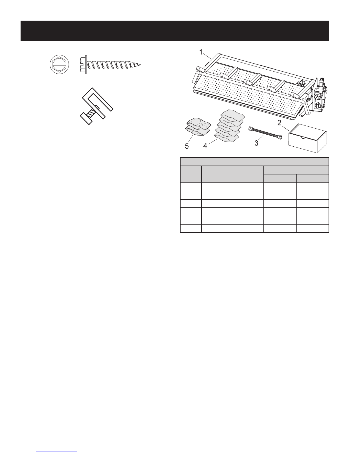
CARTON CONTENTS & HARDWARE PACK
HARDWARE PACK CONTENTS
1/4" X 1 1/4" SLOTTED HEX HEAD ANCHOR SCREW (2)
DAMPER CLAMP (1)
Items not shown to scale.
CARTON CONTENTS
BFR(2124,30)RN
INDEX
NO.
1 Burner Assembly 1 1
2 Remote And Receiver Kit 1 1
3 Flexline 1 1
4 Rockwool Mix 5 5
5 Lava Rock 2 2
NS Fiber Heat Sink 1 1
DESCRIPTION
QUANTITY SUPPLIED
BFR2124 BFR30
See Parts Lists on page 22 for ordering replacement parts.
Do not order batteries, bolts, screws, washers or nuts. They are
standard hardware items and can be purchased at any local
hardware store.
39246-0-0718Page 4
Page 5
IMPORTANT SAFETY INFORMATION
Installer: Leave these instructions with the owner. For Installation
In Solid Fuel Burning Fireplaces. Do not burn wood or solid fuels
in a replace where a decorative gas log set is installed. This
appliance is for installation only in a solid fuel burning replace,
masonry replace or manufactured replace.
WARNING
Before installing in a solid fuel burning replace, the chimney
ue and rebox must be cleaned of soot, creosote, ashes
and loose paint by a qualied chimney cleaner.
WARNING
Do not allow fans to blow directly into or at the replace.
Avoid any drafts that alter burner ame patterns.
WARNING
Do not use a blower insert, heat exchanger insert or other
accessory not approved for use with this appliance.
DANGER
Any modication to this gas log set or to controls can be
dangerous. Improper installation or use of the gas log set
can cause serious injury or death from re, burns, explosion or carbon monoxide poisoning.
WARNING
Do not operate this burner with glass doors closed.
• Installation and repair must be done by a QUALIFIED
SERVICE PERSON. The appliance should be inspected
before use and at least annually by a qualied service
person. More frequent cleaning may be required due to
excessive lint from carpeting, bedding materials, etc. It
is imperative that control compartments, burners and
circulating air passageways of the appliance be kept clean.
• Dot not place clothing or other ammable material on or near
the appliance.
• Do not place trash or other articles on the log set during
operation.
• Do not put anything around the replace that will obstruct the
ow of ventilation air.
• Do not use this appliance if any part has been under water.
Immediately call a qualied service technician to inspect the
appliance and to replace any part of the control system and
any gas control which has been under water.
• Do not use thermostats on vented burner applications
• Keep the appliance area clear and free from combustible
material, gasoline and other ammable vapors and liquids.
• Keep burner and control compartment clean.
• A yearly examination and cleaning of the venting system
of the solid-fuel burning replace must be performed by a
qualied agency.
• Make a periodic visual check of pilot and burners. Clean and
replace damaged parts.
• Alert children and adults to the hazards of high surface
temperatures and caution them to stay away to avoid burns
or clothing ignition.
• Carefully supervise young children when they are in the
same room as the appliance.
• During manufacture, this burner is treated with certain oils,
lms and bonding agents. These substances are not harmful
but may produce smoke and odors as they burn off during
initial operation of the replace. This is normal. Open a
window during the initial bake out period.
•
Proper installation, burner pan location and log placement
is important to achieve optimum look and performance of
your gas log set. Follow the log assembly sequence for
proper operation.
• Do not operate this log set with glass doors in the closed
position. A replace screen must be in place when the log
set is burning. Adequate combustion air must be provided for
proper venting. All ames should go up and out the top of the
rebox into the ue vent. If any ames oat or curl forward
into the room do not operate appliance. Check for an open
ue and adequate combustion air into the room. A damper
clamp must be installed on the rebox damper to maintain
an open ue. See page 10.
• Young children must be carefully supervised when they are
in the same room as the gas log while in operation. Do not
place stockings, clothing or any ammable material above or
near the replace.
• Do not substitute or use materials other than those supplied
for use with the log set.
WARNING
Follow all gas leak check procedures in this manual, prior
to operation.
WARNING
Fuels used in gas or oil-red appliances, and the products
of combustion of such fuels, contain chemicals known to
the State of California to cause cancer, birth defects, and/
or other reproductive harm. This warning is issued pursuant to California Health & Safety Code Sec. 25249.6.
DO NOT ATTEMPT TO DISCONNECT THE GAS OR ANY GAS
FITTING WHILE THIS APPLIANCE IS IN OPERATION.
NEVER leave the decorative gas log set unattended while in
operation.
NEVER allow children to operate this decorative gas log set.
NEVER place hands or ngers on the front-edge of this
decorative gas log set.
NEVER use liquid propane gas in a natural gas unit, or natural
gas in a liquid propane unit.
DO NOT use solid-fuel or lighter uid in any decorative gas log set.
Any safety screen or guard removed for servicing an appliance
must be replaced prior to operating the appliance.
39246-0-0718 Page 5
Page 6
IMPORTANT SAFETY INFORMATION (CONT'D)
WARNING
Do not use this appliance if any part has been under water.
Immediately call a qualied service technician to inspect
the appliance and replace any part of the control system
and any gas control that has been under water.
All units with gas control valves must be lit by a Safety Pilot. The
pilot is located at the right, rear of the unit.
Follow these instructions exactly when lighting the appliance.
BEFORE LIGHTING, smell around the appliance area for gas. Be
sure to smell next to the oor, as propane gas is heavier than air
and will settle to the oor. Use only your hand to rotate the gas
control knob. Never use tools. If the knob will not turn by hand, do
not try to repair it; call a qualied service technician or installer.
Force or attempted repair may result in a re or explosion.
WARNING
All gas burning appliances produce smoke and carbon monoxide gas during operation. These fumes can be harmful if the
appliance is used in any other than a fully vented replace.
WARNING
The Commonwealth of Massachusetts requires that the
chimney ue damper, when used with decorative gas log
sets, be welded open or completely removed. In the Commonwealth of Massachusetts, this appliance must be in-
stalled by a licensed plumber or gastter.
GAS WARNING ODOR
If a gas leak happens, you should be able to smell the gas
because of the odorant put in the propane gas.
That’s your signal to go into immediate action!
• Do not operate electric switches, light matches, use your phone.
Do not do anything that could ignite the gas.
• Get everyone out of the building, vehicle, trailer, or area. Do
that IMMEDIATELY.
• Close all gas tank or cylinder supply valves.
• Propane gas is heavier than air and may settle in low areas
such as basements. When you have reason to suspect a gas
leak, keep out of basements and other low areas. Stay out until
reghters declare them to be safe.
• Use your neighbor’s phone and call a trained propane gas
service person and the re department. Even though you may
not continue to smell gas, do not turn on the gas again. Do not
re-enter the building, vehicle, trailer, or area.
• Finally, let the service man and reghters check for escaped
gas. Have them air out the area before you return. Properly
trained propane gas service people should repair the leak, then
check and relight the gas appliance for you.
WARNING
Improper installation, adjustment, alteration, service or maintenance, can cause property damage, personal injury or loss
of life. Refer to the owner’s information manual, provided with
this appliance. Installation and service must be performed by
a qualied installer, service agency or the gas supplier.
39246-0-0718Page 6
Page 7

SAFETY INFORMATION FOR USERS OF PROPANE GAS
Propane Gas is a ammable gas which can cause res and
explosions. In its natural state, propane is odorless and colorless. You may not know all the following safety precautions
which can protect both you and your family from an accident.
Read them carefully now, then review them point by point with
the members of your household. Someday when there may not
be a minute to lose, everyone's safety will depend on knowing
exactly what to do. If, after reading the following information,
you feel you still need more information, please contact your
gas supplier.
NO ODOR DETECTED - ODOR FADE
Some people cannot smell well. Some people cannot smell
the odor of the chemical put into the gas. You must nd out if
you can smell the odorant in propane. Smoking can decrease
your ability to smell. Being around an odor for a time can affect your
sensitivity or ability to detect that odor. Sometimes other odors in
the area mask the gas odor. People may not smell the gas odor or
their minds are on something else. Thinking about smelling a gas
odor can make it easier to smell.
The odorant in propane gas is colorless, and it can fade under
some circumstances. For example, if there is an underground
leak, the movement of the gas through soil can lter the odorant.
Odorants in propane gas also are subject to oxidation. This fading
can occur if there is rust inside the storage tank or in iron gas pipes.
The odorant in escaped gas can adsorb or absorb onto or into
walls, masonry and other materials and fabrics in a room. That will
take some of the odorant out of the gas, reducing its odor intensity.
Propane gas may stratify in a closed area, and the odor intensity
could vary at different levels. Since it is heavier than air, there may
be more odor at lower levels. Always be sensitive to the slightest gas
odor. If you detect any odor, treat it as a serious leak. Immediately
go into action as instructed earlier.
SOME POINTS TO REMEMBER
• Learn to recognize the odor of propane gas. Your local pro-
pane gas dealer can give you a “Scratch and Sniff” pamphlet.
Use it to nd out what the propane odor smells like. If you
suspect that your propane gas has a weak or abnormal odor,
call your propane gas dealer.
• If you are not qualied, do not light pilot lights, perform service,
or make adjustments to appliances on the propane gas system.
If you are qualied, consciously think about the odor of propane
gas prior to and while lighting pilot lights or performing service
or making adjustments.
• Sometimes a basement or a closed-up house has a musty
smell that can cover up the propane gas odor. Do not try to
light pilot lights, perform service, or make adjustments in an
area where the conditions are such that you may not detect
the odor if there has been a leak of propane gas.
• Odor fade, due to oxidation by rust or adsorption on walls of
new cylinders and tanks, is possible. Therefore, people should
be particularly alert and careful when new tanks or cylinders
are placed in service. Odor fade can occur in new tanks, or
reinstalled old tanks, if they are lled and allowed to set too
long before relling. Cylinders and tanks which have been out
of service for a time may develop internal rust which will cause
odor fade. If such conditions are suspected to exist, a periodic
sniff test of the gas is advisable. If you have any question
about the gas odor, call your propane gas dealer. A periodic sniff test of the propane gas is a good safety measure
under any condition.
• If, at any time, you do not smell the propane gas odorant and
you think you should, assume you have a leak. Then take the
same immediate action recommended above for the occasion
when you do detect the odorized propane gas.
• If you experience a complete “gas out,” (the container is under
no vapor pressure), turn the tank valve off immediately. If the
container valve is left on, the container may draw in some air
through openings such as pilot light orices. If this occurs, some
new internal rusting could occur. If the valve is left open, then
treat the container as a new tank. Always be sure your container is under vapor pressure by turning it off at the container
before it goes completely empty or having it relled before it is
completely empty.
39246-0-0718 Page 7
Page 8

GENERAL INFORMATION
Qualied Installing Agency
Installation and replacement of gas piping, gas utilization equipment
or accessories and repair and servicing of equipment shall be per-
formed only by a qualied agency. The term "qualied agency" means
any individual, rm, corporation or company which either in person
or through a representative is engaged in and is responsible for (a)
the installation or replacement of gas piping or (b) the connection,
installation, repair or servicing of equipment, who is experienced in
such work, familiar with all precautions required and has complied
with all the requirements of the authority having jurisdiction.
Commonwealth of Massachusetts: The installation must be
made by a licensed plumber or gas tter in the Commonwealth
of Massachusetts.
The installation and the provisions for combustion and ventilation
air must conform with the National Fuel Gas Code, ANSI Z223.1/
NFPA54* Canadian Installation Code CAN/CGA B149.
*Available from the American National Standards Institute, Inc. 11
West 42nd St., New York, N.Y. 10018.
High Altitude Installation
When installing this unit at an elevation above 2000 feet (in the
United States) it may be necessary to decrease the input rating by
changing the existing burner orice to a smaller size. Generally,
input should be reduced 4 percent for each 1000 feet above sea
level. However, if the heating value of the gas has been reduced,
this general rule may not apply. Check with local gas utility for proper
orice size identication.
For Canadian high altitude applications, this appliance is suitable for
installation at elevations between 0 feet (0m) and 4,500 (1,370m)
without change.
When installing this unit at an elevation above 4500 feet (1,370m)
(in Canada), check with local authorities.
Consult your local gas utility for assistance in determining the proper
orice for location.
39246-0-0718Page 8
Page 9
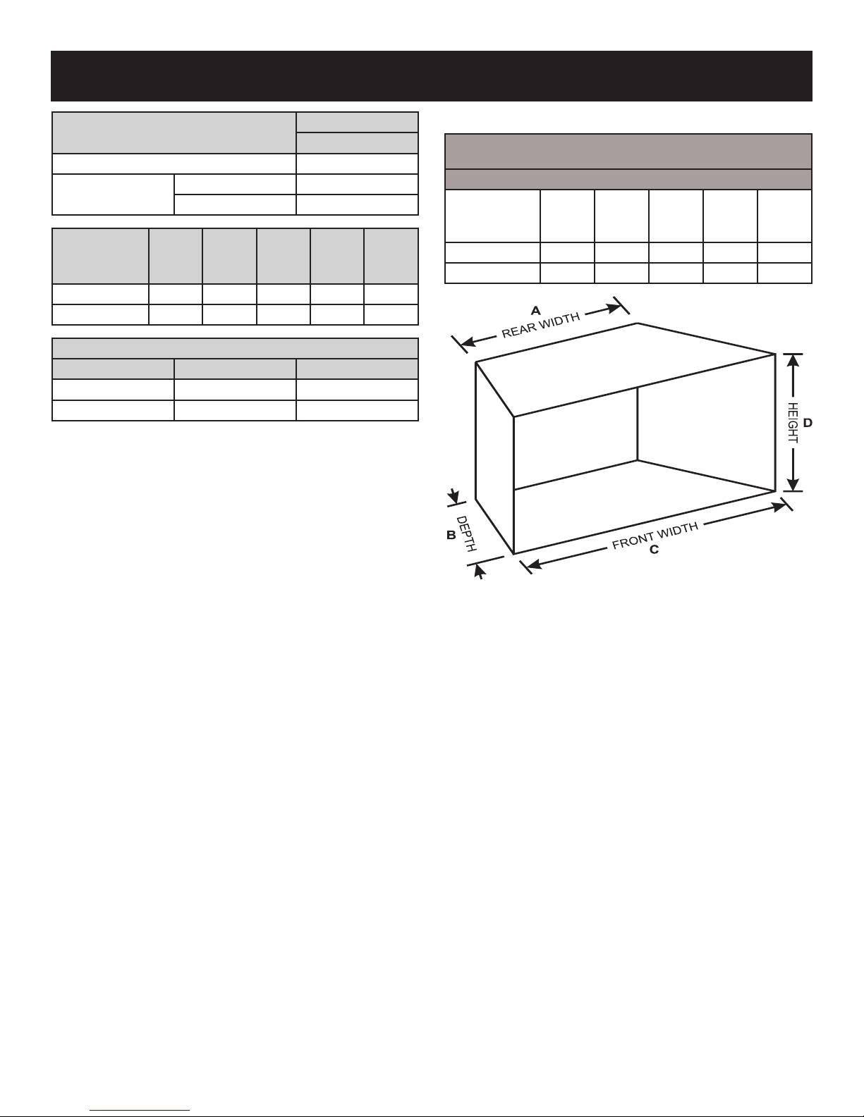
PRODUCT SPECIFICATIONS
NATURAL GAS
Millivolt
Regulator pressure setting 4.5"
Gas inlet pressure
Model
Gas
Type
Max. 10.5"
Min. 5.0"
Valve
Type
Orice
Manifold
Pressure
(w.c.)
BFR2124RN Natural Hi/Low #22 4.5" 55,000
BFR30RN Natural Hi/Low #12 4.5" 65,000
PROPANE CONVERSION KIT
Burner Model Valve Type Kit Number
BFR2124RN Hi/Low CKV119
BFR30RN Hi/Low CKV120
NOTE: The air shutter setting for all models is 1/16" open.
BTUH
Max.
Rate
Determining the Correct Burner Size for Your Fireplace
MINIMUM FIREPLACE DIMENSIONS
FACTORY BUILT FIREPLACES
Chimney Height Minimum of 6 Feet
Burner
Model
Rear
WidthADepth
B
Front
WidthCHeight
D
BFR2124RN 26 16 30 20
BFR30RN 30 16 36 20
Minimum
Vent
in Sq.
Inches
49
49
Figure 1
39246-0-0718 Page 9
Page 10

INTRODUCTION
Introduction
Always consult your local Building Department regarding regulations, codes or ordinances which apply to the installation of a
vented decorative gas log set in a solid-fuel burning replace.
This appliance is only for use with the type of gas indicated on
the rating plate.
Instructions to Installer
1. Installer must leave instruction manual with owner after
installation.
2. Installer must have owner ll out and mail warranty card
supplied with the replace.
3. Installer should show owner how to start and operate the
replace.
WARNING
Any change to this appliance or its controls can be dangerous. Improper installation or use of the appliance can cause
serious injury or death from re, burns, explosion or carbon
monoxide poisoning.
General Information
Any alteration of the original design, installed other than as
shown in these instructions or use with a type of gas not
shown on the rating plate is the responsibility of the person
and company making the change.
Important
All correspondence should refer to complete Model No., Serial
No. and type of gas. This information can be found on the data
plate supplied with the burner.
NOTICE: During initial use of the logs you will detect an odor as
the logs are cured. This is normal.
WARNING
A replace screen must be in place when this appliance is
in operation. The screen shall allow for introduction of combustion air.
WARNING
When this decorative gas appliance is used in a replace
equipped with glass doors, the glass doors should remain
open during log set operation. This will maximize the radiant
heat provided to the surrounding area, and minimize overheating of any valve installation. The glass doors may be
closed when the log set is not in use.
FIREPLACE PREPARATION
• Remove all contents from the burner carton.
• Check the contents of the carton against the parts list in this
manual. Report any missing or damaged parts to your dealer.
• Turn off gas supply to replace or rebox.
• Have the replace oor and chimney professionally cleaned to
remove ashes, soot, creosote or other obstructions.
Have this cleaning performed annually after installation.
•
Seal any fresh air vents or ash clean-out doors located on oor
or wall of replace. If not, drafting may cause pilot outage or
excessive sooting. Use a heat-resistant sealant. Do not seal
chimney ue damper.
Installing Damper Clamp
Remove all ashes or other debris from the replace. If the replace
is equipped with an ash dump be sure to seal the door with furnace
cement or high temperature silicone. Be sure to check the damper
for proper operation and verify that the ue passageway is open.
Attach damper clamp to the vent damper and tighten hold down bolt.
Place the clamp over the lip of the damper and tighten the hold
down bolt until the clamp is securely attached to the damper. This
will prevent the damper from accidentally closing.
Figure 2
39246-0-0718Page 10
Page 11

GAS SUPPLY
Check all local codes for requirements, especially for the size and
type of gas supply line required.
RECOMMENDED GAS PIPE DIAMETER
Pipe
Length
0-10 feet 1/2-in 3/8-in 1/2-in 3/8-in
10-40 feet 1/2-in 1/2-in 5/8-in 1/2-in
40-100 feet 1/2-in 1/2-in 3/4-in 1/2-in
100-150 feet 3/4-in 1/2-in 7/8-in 3/4-in
NOTICE: Never use plastic pipe. Check to conrm whether your
local codes allow copper tubing or galvanized.
NOTICE: Since some municipalities have additional local codes, it
is always best to consult your local authority and installation code.
Installing a New Main Gas Shut-Off Valve
Each appliance should have its own manual gas shut-off valve.
In the Commonwealth of Massachusetts the gas shut-off valve must
be a T handle type.
A manual main gas shut-off valve should be located in the vicinity
of the unit. Where none exists, or where its size or location is not
adequate, contact your local authorized installer for installation or
relocation.
Compounds used on threaded joints of gas piping shall be
resistant to the action of liqueed petroleum gases. The gas lines
must be checked for leaks by the installer. Testing for leaks on
all exposed connections should be done with leak detection test
solution. After testing is complete, all solution should be cleaned
off. On unexposed connections, a pressure test should be made.
Never use an exposed ame to check for leaks. Appliance must
be disconnected from piping at inlet of control valve and pipe
capped or plugged for pressure test. Never pressure test with
appliance connected; control valve will sustain damage!
A gas valve and ground joint union should be installed in the gas
line upstream of the gas control to aid in servicing. It is required by
the National Fuel Gas Code that a drip line be installed near the gas
inlet. This should consist of a vertical length of pipe tee connected
into the gas line that is capped on the bottom in which condensation
and foreign particles may collect.
The use of the following gas connectors is recommended:
— ANSI Z21.24 Appliance Connectors of Corrugated Metal Tubing
and Fittings
— ANSI Z21.45 Assembled Flexible Appliance Connectors of
Other Than All-Metal Construction
Schedule 40 Pipe
Inside Diameter
Natural Propane Natural Propane
Tubing, Type L
Outside Diameter
Figure 3
The above connectors may be used if acceptable by the authority
having jurisdiction. The Commonwealth of Massachusetts requires
that a exible appliance connector cannot exceed three feet in length.
A gas valve and ground joint union should be installed in the gas
line upstream of the gas control to aid in servicing. It is required
by the National Fuel Gas Code that a drip leg be installed near the
gas inlet. See Figure 4. This should consist of a vertical length of
pipe tee connected into the gas line that is capped on the bottom
in which condensation and foreign particles may collect.
39246-0-0718 Page 11
Figure 4
Page 12

GAS SUPPLY (CONT'D)
Pressure Testing of the Gas Supply System
1. To check the inlet pressure to the gas valve, use the test gauge
connection described below.
2. The appliance and its individual shutoff valve must be
disconnected from the gas supply piping system during any
pressure testing of that system at test pressures in excess of
1/2 psig (3.5 kPa).
3. The appliance must be isolated from the gas supply piping system
by closing its individual manual shutoff valve during any pressure
testing of the gas supply piping system at test pressures equal
to or less than 1/2 psig (3.5 kPa).
CAUTION
If one of the procedures results in pressures in excess of 1/2
psig (14-in w.c.) (3.5 kPa) on the appliance gas valve, it will
result in a hazardous condition.
Checking Manifold Pressure
Millivolt Natural Gas models will have a manifold pressure of ap-
proximately 3.5-in w.c. (.871kPa) at the pressure regulator outlet
with the inlet pressure to the pressure regulator from a minimum
of 5.0-in w.c. (1.120kPa) for the purpose of input adjustment to a
maximum of 10.5-in w.c. (2.615kPa). Manual Natural Gas models
will have a manifold pressure of approximately 5.3-in w.c. (1.12kPa)
at the pressure regulator outlet with the inlet pressure to the pressure
regulator from a minimum of 6.0-in w.c. (1.74kPa) for the purpose
of input adjustment to a maximum of 10.5-in w.c. (2.615kPa).
Manual
*NOTICE: A test gage connection is located downstream of the
gas appliance pressure regulator for measuring gas pressure. The
connection is a 1/8 inch 3mm) N.P.T. plugged tapping.
Millivolt
*NOTICE: The gas control is equipped with a captured screw-type
test gauge connection.
39246-0-0718Page 12
Page 13

INSTALLATION
Gas supply system must be installed in accordance with the U.S.
National Fuel Gas Code.
This appliance and its individual shut off valve must be disconnected from the gas supply piping system during any system
pressure test in excess of 1/2 PSI (3.5 KPA).
Use a system manual shut off valve to shut off the gas supply to
this gas appliance before continuing with installation procedures.
DANGER
To avoid injury and property damage, DO NOT obstruct the
ow of combustion and ventilation air when installing or
operating the appliance.
IMPORTANT
Seal any fresh air vents or ash clean-out doors located on the
oor or wall of the replace. If this is not performed, drafting
may cause pilot outage or excessive sooting. Use a heat-
resistant sealant. DO NOT seal the chimney ue damper.
IMPORTANT
BEFORE YOU BEGIN - Check the gas pressure at the
replace stub to ensure proper minimum gas pressure (see the
specications beginning on page 9 of this manual).
ANCHOR SCREWS
Figure 5
BFR MODEL FRONT AND REAR
IMPORTANT
BEFORE YOU BEGIN - Ensure that the rebox meets the
minimum specications of the appliance (see the specications
beginning on page 9 of this manual).
IMPORTANT
This appliance when rst installed and used may produce
odors. This is normal. Open a window when operating the
appliance for the rst time.
IMPORTANT
This appliance must be installed only in a solid-fuel burning
replace, which contains a working ue and is constructed of
non-combustible materials.
You must secure the gas burner to the replace oor. If not, the
entire unit may move when you adjust the controls. Movement
of unit may cause shifting of the gas logs which leads to
excessive sooting and improper burning. See Figure 5.
Special care is required if you are installing the unit into a
sunken replace. You must raise the replace oor with non-
combustible material to allow access to gas log controls.
This will ensure adequate air ow and guard against sooting.
Raise the replace oor using noncombustible materials.
ASSEMBLY PROCEDURE:
1. Place the burner in the replace or rebox. Make certain the
entire ember burner is inside the front edge of the replace
or rebox.
2. An anchor hole is provided in each burner leg. After cen-
tering the burner, mark the hole positions on the replace/
rebox oor. Drill two 5/32 inch diameter holes approximately
1-1/2 inches deep for masonry screws or 1/8 inch hole for
sheet metal screws.
3. Anchor to the replace/rebox oor using the screws provided. Refer to Figure 5.
Figure 6
39246-0-0718 Page 13
Page 14

INSTALLATION (CONT'D)
WARNING
Failure to position the parts in accordance with all included
pictures, diagrams and drawings, or failure to use only
parts specically approved with this appliance may result
in property damage or personal injury.
4. Spread the rock wool over the burner. The rock wool should
be broken into uffy quarter-sized pieces.
Figure 7
5. Place the lava rock around the burner assembly.
WARNING
Apply loose material (rockwool and lava rock) per instruction
manual. DO NOT apply extra material not supplied with this
appliance. All previously applied loose material (rock wool)
must be removed prior to reapplication.
CAUTION
DO NOT place rockwool or lava rock in the area of the
safety pilot assembly.
STOP!
The LKF Fiber Log Set and LPR2430 Refractory Log Set are the
only two log sets which are approved for use on these burners.
DO NOT substitute a different log set or deviate from the log
placement sequence.
Refer to the instructions packaged with your Decorative Gas Logs.
6.
Remove all contents from the Decorative Gas Log carton.
7. Check the contents of the carton against the parts list in the
manual. Report any missing or damaged parts to your retailer.
8. Remove any and all protective wrapping from the gas logs.
9. Arrange the decorative gas logs on the burner according to
the instructions.
NOTICE: The Commonwealth of Massachusetts requires that the
chimney ue damper, when used with decorative gas log sets, be
welded open or completely removed.
Figure 8
Figure 9
6. Place remote receiver in the front right corner of rebox and
cover with lava rock as shown in Figure 9.
39246-0-0718Page 14
Page 15

DOOR OPERATION
CAUTION
Operate the replace with the bifold glass doors in
only the fully open position.
NOTE: Always close the mesh rescreens when operating
the replace with the glass doors fully open.
CORRECT DOOR POSITION WHEN
OPERATING THE FIREPLACE
FULLYOPEN DOORS
Figure 10
INCORRECT DOOR POSITION WHEN
OPERATING THE FIREPLACE
PARTIALLYOPEN DOORS.
WARNING
DO NOT operate the replace with the doors partially open or closed. Operating the replace with the
doors partially open or closed creates a hazardous
situation.
• Partially open doors can cause sooting on front
of the replace.
• Closed doors can cause the glass to overheat
and shatter.
Figure 11
39246-0-0718 Page 15
Page 16

HI / LOW LIGHTING INSTRUCTIONS
FOR YOUR SAFETY READ BEFORE LIGHTING
WARNING
If you do not follow these instructions exactly, a re or explosion may result causing property damage,
personal injury or loss of life.
A. This appliance has a pilot which must be lighted by hand.
When lighting the pilot, follow these instructions exactly.
B. BEFORE LIGHTING smell all around the appliance area
for gas. Be sure to smell next to the oor because some
gas is heavier than air and will settle on the oor.
WHAT TO DO IF YOU SMELL GAS
• Do not try to light any appliance.
• Do not touch any electrical switch;
do not use any phone in your building.
• Immediately call your gas supplier from a neighbor's
phone. Follow the gas supplier's instructions.
• If you cannot reach your gas supplier, call the re
department.
C. Use only your hand to push in or turn the gas control
knob. Never use tools. If the knob will not push in or
turn by hand, don't try to repair it; call a qualied service
technician. Force or attempted repair may result in a re
or explosion.
D. Do not use this appliance if any part has been under
water. Immediately call a qualied service technician to
inspect the appliance and to replace any part of the control
system and any gas control which has been under water.
LIGHTING INSTRUCTIONS
WARNING
• Any glass doors shall be opened when the appliance is in operation.
• A replace screen must be in place when the appliance is operating and the screen shall have an opening(s) for
introduction of combustion air.
1. STOP! Read the safety information or other side of plate.
2. Push in gas control knob slightly and turn clockwise
to "OFF". Do not force.
3. Turn gas ow adjustment knob clockwise either
manually or with remote control to "OFF".
4. Wait ten (10) minutes to clear out any gas. Then smell for
gas, including near oor. If you smell gas, STOP! follow "B"
in the safety information on other side. If you do not smell
gas, go to the next step.
5. Find pilot - the pilot is attached to the rear-right of the burner.
6. Turn gas control knob counterclockwise to "IGN".
7. Depress and turn gas control knob counterclockwise
to "PILOT". A spark is produced when gas
control knob is turned between "IGN" and "PILOT".
Repeatedly depress and turn gas control knob between
"IGN" and "PILOT" until pilot is ignited. Continue to hold
the control knob in for about one (1) minute after pilot is lit.
Release knob and it will pop back up. Pilot should remain
lit. If it goes out repeat steps 2 through 7.
• If knob does not pop up when released, stop and
immediately call your service technician or gas supplier.
• If the pilot will not stay lit after several tries, turn the
gas control knob to "OFF" and call your service.
TO TURN OFF GAS TO APPLIANCE
8. Attention! Gas control has an INTERLOCK latching device.
When the pilot is initially lit and the safety magnet is
energized (pilot stays on) the INTERLOCK latching device
becomes operative. If the gas control is turned to the "OFF"
position or gas ow to the appliance is shut off, the pilot
cannot be relighted until the safety magnet is de-energized
(approximately 60 seconds). There will be an audible "click"
when the safety magnet in the gas control is de-energized.
Pilot can now be relighted. Repeat step 2 through 7.
9. Turn gas control knob counterclockwise to "ON".
10. Turn gas ow adjustment knob counterclockwise
either manually or with remote control between
"OFF" and "ON" to adjust ame height.
1. Set the ON/OFF switch to "OFF".
2. Push in gas control knob slightly and turn clockwise
to "OFF". Do not force.
39246-0-0718Page 16
Page 17

PILOT AND MAIN BURNER FLAME CHARACTERISTICS
Pilot Flame Pattern
Figure 12 shows a correct pilot ame pattern. The correct ame
will be blue and will extend beyond the thermocouple/thermopile.
The ame will surround the thermocouple/thermopile just below
the tip. A slight yellow ame may occur where the pilot ame and
main burner ame meet.
After use, cleaning of the pilot burner may be required for the proper
ame. The pilot orice can be cleaned with high pressure air or
by placing under running water. Pilot orice must be dry before
replacement. Use canned air to clean inside the pilot after the pilot
orice has been removed.
To Remove Pilot Orice
1. Disconnect the pilot supply line at the pilot burner.
2. Remove pilot orice from pilot burner. It may be necessary to
tap on pilot burner in order to remove the pilot orice.
Pilot Flame Pattern
Figure 12
If pilot ame pattern is incorrect -
• See Troubleshooting, page 21.
Main Burner Flame Pattern
The main burner ame will be yellow with a blue base.
Main Burner Flame Ignition and Extinction
When the main burner is ignited it will take a few seconds for the
full ame pattern to develop.
When the main burner is extinguished it will take a few seconds for
the ames to disappear. It is normal to have the ames burn down
near the rock wool, as the remaining gas is burned.
39246-0-0718 Page 17
Page 18

HI / LOW (BFR) WIRING
NOTICE: Thermostats are not approved on vented decorative
appliances.
Label all wires prior to disconnection when servicing controls. Wiring
errors can cause improper and dangerous operation. Verify proper
operation after servicing.
The gas valve does not require 24 or 110 volts. See pages 19 - 21
for remote control instructions.
It is important to use wire of a proper gauge for the length of the wire:
RECOMMENDED WIRE GAUGES
Maximum Length Wire Gauge
1' to 10' 18
10' to 25' 16
25' to 35' 14
Remote Receiver
Use the following steps to place the remote receiver adjacent to
the gas valve.
Attention:
1. The remote receiver cannot be placed behind the gas valve and
burner assembly.
2. When facing the appliance, the remote receiver must be placed
in the right side rebox, toward the front.
Wiring Diagram
Figure 13
NOTICE: Do not let remote control receiver come in contact with
burner assembly.
Refer to remote control installation and operating instructions for
more details on remote control.
39246-0-0718Page 18
Page 19

REMOTE OPERATION
APPLICATION
GV34 is a servo motor operated valve with remote control
allowing for innite adjustment from low re to hire re.
GENERAL NOTES
Radio Frequency Remote
868 MHz for Europe; 915 MHz for U.S. (FCC ID:
UX5-R300) and for Canada (IC: 4943-R300).
This device complies with part 15 of the FCC Rules.
Operation is subject to the following two conditions: (1)
This device may not cause harmful interference, and
(2) This device must accept any interference received,
including interference that may cause undesired operation.
Changes or modications not expressly approved by the
party responsible for compliance could void the user's
authority to operate the equipment.
Batteries Remote Handset:
2 X 1.5V "AAA"
(quality alkaline
recommended)
Batteries Receiver:
4 X 1.5V "AA"
(quality alkaline
recommended).
Battery
Replacement
Battery
replacement is
recommended
at the beginning
of each heating
season. Do not
use metal tools to
remove batteries.
Using a metal tool
could cause a short
that may damage
the receiver.
Location Of
Receiver
See page 14.
STANDARD HANDSET FEATURES
AM
PM
°F
°C
Figure 14:
R300 Standard
Model, Patented
LCD Icon Features And Description
Sleep Mode Icon. After 8 hours of no
signal between the handset and the
receiver, valve runs to pilot and Sleep
Mode icon is displayed.
Ambient Temperature Display: Indicates
the current room temperature. °F or °C
Child Safety Lock: When ON (icon
showing), the right button must be pushed
twice within 0.5 seconds to increase the
ame height.
Battery Life Indicator: 4 bars indicates a
fully charged battery.
Clock Mode: Set to 12 or 24 hour clock.
Communication Indicator: Indicates the
handset is transmitting to the receiver.
INITIAL SETUP
SETTING THE ELECTRONIC CODE
Radio Frequency Remote
A code is selected automatically for all Mertik Maxitrol
electronics from among 65,000 random codes available.
On initial and subsequent receiver battery changes, the
receiver has to learn the code of the handset.
Figure 15:
R300 Standard
Model Icons
39246-0-0718 Page 19
• Power up Handset
• Power up Receiver (LED blinks).
• While blinking, press any button.
• When the Receiver LED stops blinking, the code is set.
NOTE: These remote handset and receiver are not
interchangeable with previous versions. For all lighting
instructions please refer to appliance manufacturer's
instructions.
Page 20

REMOTE OPERATION (CONT'D)
WARNING
Read through this entire warning before attempting
initial setup / programming.
A red number/icon indicates the icon is blinking. This
will help determine which menu item is being set or
programmed.
When programming a menu item, use the right (up)
button ONLY. Pressing the left (down) button will
cause the programming menu to skip to the next
menu item. If you accidentally skip to the next menu
item, you must cycle through all the menu items to
return to the item you were programming.
When adjusting a menu item, the number will scroll
up only (1, 2, 3...) and will cycle back to the beginning
number.
15 seconds of inactivity will cause the remote to
automatically go to operation mode. Follow Step 1.
INITIAL SETUP - PROGRAMMING MODE to return to
programming mode. Any changes will be saved each
time you exit programming mode.
INITIAL SETUP - PROGRAMMING MODE
INITIAL SETUP - PROGAMMING MODE (CONT'D)
SETTING THE MINUTES
:
SETTING CHILD SAFETY LOCK
This concludes your basic programming. The remote will
automatically save your changes and go to operation
mode after 15 seconds of inactivity.
STANDARD HANDSET OPERATION
FLAME HEIGHT ADJUSTMENT
4. Press
• Press (down) button to set
5. Set Child Safety Lock either ON or
• Press (up) button to set Child
Minutes. 00-59.
NOTE: Use right (up) button only.
Numbers scroll up (1, 2, 3...) to 59
then cycle back to 00.
and scroll to the next menu item.
OFF.
Safety Lock ON (icon showing) or
OFF.
(up) button to set
• Press
• Press (down) to scroll through menu items.
• Press (up) to adjust menu items.
SETTING °F OR °C
SETTING 12 HOUR OR 24 HOUR MODE
SETTING THE HOUR
(until screen blinks) to enter Programming Mode.
(both buttons) and hold for 5 seconds
1. Press (up) button to choose
either °F or °C.
• Press (down) button to set
and scroll to the next menu item.
2. Press (up) button to choose
either “12” or “24”.
• Press (down) button to set
and scroll to the next menu item.
3. Press (up) button to set the
AM
Hour, 1-12 or 0-23.
NOTE: Use the (up) button only.
Numbers scroll up (1, 2, 3,...) to 12
or 23 then cycle back to 1 or 0.
• Press (down) button to set
and scroll to the next menu item.
PAGE 3
• To turn the main burner ON or to increase the ame
height, press the (up) button.
• To decrease the ame height, press the (down)
button or turn main burner OFF.
39246-0-0718Page 20
Page 21

REMOTE OPERATION (CONT'D)
SLEEP MODE
After 8 hours of no signal between the handset and the
receiver valve runs to pilot and the Sleep Mode icon is
displayed.
TURN OFF GAS TO APPLIANCE
Access the gas control.
Turn the main valve knob clockwise to the PILOT
position. Push in knob; turn and release. Continue turning
to the OFF full clockwise position.
Replace appliance accessibility cover (if applicable).
MANUAL VALVE OPERATION
1. STOP! Read the safety information included before
proceeding.
2. Turn main valve knob to the OFF full clockwise
position.
3. Turn the MANUAL knob to the full clockwise
position.
4. Wait ve (5) minutes to clear out any gas. Verify that
no gas is in the area around the appliance, including
near the oor. If you detect gas STOP! Follow
Warnings (see pg. 16) under “What to do if you
smell gas”. If no gas is present, proceed to step 5.
5. Turn main valve knob slightly counterclockwise
towards the IGN position unitl it stops, then
press down and continue turning counterclockwise
to the pilot position. Continue to hold down
knob for 10 seconds after pilot burner has been lit. If
pilot does light, steps 1 and 2 may be repeated.
NOTE: If the pilot does not stay lit after several tries,
turn main valve knob to the PILOT position. Push in
knob; turn and release. Continue turning to the OFF
full clockwise position and proceed to step 7.
6. Upon lighting, release knob and turn main valve knob
fully counterclockwise to ON position.
7. If the appliance will not operate, follow the
instructions “Turn Off Gas to Appliance”.
MANUAL FLAME HEIGHT OPERATION
The motorized valve is equipped with a slip clutch allowing
manual adjustment of the main burner by turning the
manual knob. When turning the manual knob, do not force.
STANDBY PROCEDURE
Turn main valve knob clockwise to Pilot position,
allowing only pilot gas to ow.
39246-0-0718 Page 21
Page 22

MAINTENANCE AND SERVICE
Maintenance
The Decorative Gas Log Set should be thoroughly inspected at
least once a year by a qualied technician.
At the beginning of each season, check for:
• Chimney ue or vent pipe is drawing properly, and that vent
pipe connections are tight.
• Blockages at the chimney or vent termination.
• Creosote and soot build-up in chimney and/or vents (clean if
necessary).
• Inspect the pilot and burners.
• Remove dust, cobwebs, pet hair or other debris from the
replace.
• Check for gas leaks. See page 11.
The burner system has been adjusted for proper operation at the
factory. No adjustment is necessary, other than altitude de-rate or
pilot ame.
WARNING
NEVER enlarge valve orices or burner ports.
Sooting
Some sooting of your log set is normal, adding to the appearance
of burned wood. If excessive sooting accumulates, clean the logs
using either of the following options::
A.
When the logs are cold, remove logs from burner, brush the
soot off with a brush. Do not use water or soot cleaners.
B. When the logs are cold, remove logs from burner. Take
logs outside and remove soot with an air hose. Refer to
Installation Instructions supplied with logs for re-installation information.
Cleaning
Keep the control area, logs and burner area surrounding the logs clean.
THE LOGS CAN GET VERY HOT— HANDLE ONLY WHEN COOL.
Always keep the appliance area clear and free from combustible
materials, gasoline, and other ammable vapors and liquids.
Never obstruct the ow of combustion and ventilation air. Keep the
front of the appliance clear of all obstacles and materials.
Inspecting Venting System
A vented replace venting system is designed and constructed
to develop a positive ow adequate to remove ue gases to the
outside atmosphere.
Any foreign objects in the venting system, may cause ue gases
to ow into the room.
Periodic examination and/or cleaning of the venting system of the
solid-fuel burning replace must be done by a qualied service
person. Visually inspect the damper and ue area for excessive
soot build-up. This soot (carbon) may be removed by brushing with
a soft bristle brush.
39246-0-0718Page 22
Page 23

TROUBLESHOOTING
PROBLEM OBSERVED POSSIBLE CAUSE CORRECTIVE MEASURE
Gas odor during setup Gas Leak
Gas odor before rst ignition Gas Leak
No gas to pilot Make sure gas is on, in pilot position
Thermocouple not hot Depress valve knob for at least 1 minute
Pilot will not ignite, or will not
stay lit
Delayed ignition
Burner does not light but pilot
remains on
Burner lights but does not
stay lit while pilot remains on
Burner & pilot light but will not
stay on
Incorrect burner ame
Backre of burner
Appliance produces unwanted
odors
Logs appear to smoke
Whistle noise from appliance
Improper pilot ame adjustment See Pilot Characteristics - adjust ame
Loose connections on the thermocouple Check gas connections
Faulty pilot or thermocouple Replace Safety Pilot
Faulty valve Replace Valve
Low gas pressure Check gas supply pressure
Clogged or dirty burner ports Clean burner ports
Blocked orice Check orice opening
Faulty valve Replace valve
Low gas pressure Check gas supply pressure
Clogged or dirty burner ports Clean burner ports
Blocked orice Check orice opening
Faulty pilot or thermocouple Replace safety pilot
Faulty valve Replace valve
Low gas pressure Check gas supply pressure
Faulty valve Replace valve
Faulty pilot or thermocouple Replace Safety pilot
Clogged or dirty burner ports Clean burner ports
Low gas pressure Check gas supply pressure
Not enough fresh air for pilot Open door or window - ventilate
Faulty valve Replace valve
Faulty pilot or thermocouple Replace safety pilot
Clogged or dirty burner ports Clean burner ports
Remote control overheating Move away from ame
Remote control batteries failing Replace batteries
Incorrect gas supply or pressure Check gas supply pressure
Blocked orice Check orice opening
Clogged or dirty burner ports Clean burner ports
Faulty valve Replace valve
High altitude Adjust orice size for altitude
Blocked orice Check orice opening
Clogged or dirty burner ports Clean burner ports
Low gas pressure Check gas supply pressure
Vapors from paint, hair spray, glues, etc. Ventilate room
Initial burn-off of manufacturing chemicals Ventilate room
Vapors from manufacturing chemicals Ventilate room
Logs curing See “Curing of Refractory Logs”
Air in gas line Bleed lines
Control knob not in fully open position Open control knob to full position
Spiral gas ex line Replace gas feed line
What To Do If You Smell Gas
• Do not try to light any appliance. • Do not touch any
electrical switch; do not use any phone in your building. •
Immediately call your gas supplier from a neighbor’s phone.
Follow the gas supplier’s instructions. • If you cannot reach
your gas supplier, call the re department.
39246-0-0718 Page 23
Page 24

BFR PARTS LIST AND EXPLODED VIEW
WARNING
Failure to position the parts in accordance with these
diagrams or failure to use only parts specically
approved with this appliance may result in property
damage or personal injury.
INDEX NO. PART NO. DESCRIPTION USED ON
1 11788 Decorative Rock BFR2124 BFR30
2 15496 Rock Wool, .75 oz BFR2124 BFR30
3 38633 Valve Bracket, Hi/Low BFR2124 BFR30
4
5 P253 Fitting, Orice, 90° Angle BFR2124 BFR30
6
7 R12602 Valve, NAT Maxitrol GV34 BFR2124 BFR30
8 R11977 Venturi Gasket BFR2124 BFR30
9 R11978 Venturi BFR2124 BFR30
10 R12052 Pilot w/ Thermopile - NG BFR2124 BFR30
11 R12059 Nipple, 3/8 X 3/8 X 1 Black Iron BFR2124 BFR30
12 R12217
13 R12219
14
15 R6207 Elbow 5/16 X 3/8 90 BFR2124 BFR30
16 39028 Electrode Bracket BFR2124 BFR30
17 R2809 Damper Clamp BFR2124 BFR30
18 R1155 Electrode BFR2124 BFR30
19 R7624 Air Shutter BFR2124 BFR30
20 R12635 Remote And Receiver BFR2124 BFR30
21
NS
38340 Tube Assembly, 2124 BFR2124
38665 Tube Assembly, 30 BFR30
P273 Orice, #22 BFR2124
P325 Orice, #12 BFR30
Fitting, 1/2 Flare X 3/8 NPT Internal Threads
Flex Line, Non-Whistling 16 Inch X 1/2 Flare
R12624 Grate Weldment, 24 BFR2124
R12625 Grate Weldment, 30 BFR30
39114 Burner Assembly BFR2124
39115 Burner Assembly BFR30
38898 Fiber Heat Sink BFR2124
38899 Fiber Heat Sink BFR30
BFR2124 BFR30
BFR2124 BFR30
39246-0-0718Page 24
Page 25

MASTER PARTS DISTRIBUTOR LIST
To Order Parts Under Warranty, please contact your local Empire dealer. See the dealer locator at www.empirecomfort.com. To provide warranty service, your dealer will need your name and address, purchase date and serial number, and the nature of the problem with the unit.
To Order Parts After the Warranty Period, please contact your dealer or one of the Master Parts Distributors listed below. This list changes
from time to time. For the current list, please click on the Master Parts button at www.empirecomfort.com.
Please note: Master Parts Distributors are independent businesses that stock the most commonly ordered Original Equipment repair
parts for Heaters, Grills, and Fireplaces manufactured by Empire Comfort Systems Inc.
Dey Distributing
1401 Willow Lake Boulevard
Vadnais Heights, MN 55101
Phone: 651-490-9191
Toll Free: 800-397-1339
Website: www.deydistributing.com
Parts: Heater, Hearth and Grills
East Coast Energy Products
10 East Route 36
West Long Branch, NJ 07764
Phone: 732-870-8809
Toll Free: 800-755-8809
Fax: 732-870-8811
Website: www.eastcoastenergy.com
Parts: Heater, Hearth and Grills
HOW TO ORDER REPAIR PARTS
F. W. Webb Company
200 Locust Street
Hartford, CT 06114
Phone: 860-722-2433
Toll Free: 800-243-9360
Fax: 860-293-0479
Toll Free Fax: 800-274-2004
Websites: www.fwwebb.com & www.victormfg.com
Parts: Heater, Hearth and Grills
Parts Not Under Warranty
Parts can be ordered through your Service Person, Dealer, or a Master Parts Distributor. See this page for the Master Parts Distributors list. For best results, the service person or dealer should order parts through the distributor. Parts can be shipped directly to the
service person/dealer.
Warranty Parts
Warranty parts will need a proof of purchase and can be ordered by your Service Person or Dealer. Proof of purchase is required for
warranty parts.
All parts listed in the Parts List have a Part Number. When ordering parts, rst obtain the Model Number and Serial Number from the
name plate on your equipment. Then determine the Part Number (not the Index Number) and the Description of each part from the
following illustration and part list. Be sure to give all this information . . .
Appliance Model Number Part Description
Appliance Serial Number Part Number
Type of Gas (Propane or Natural)
Do not order bolts, screws, washers or nuts. They are standard hardware items and can be purchased at any local hardware store.
Shipments contingent upon strikes, res and all causes beyond our control.
39246-0-0718 Page 25
Page 26

WARRANTY
Empire Comfort Systems Inc. warranties this hearth product to be free from defects at the time of purchase and for the periods specied
below. Hearth products must be installed by a qualied technician and must be maintained and operated safely, in accordance with the
instructions in the owner’s manual. This warranty applies to the original purchaser only and is not transferable. All warranty repairs must
be accomplished by a qualied gas appliance technician.
Limited Lifetime – Refractory Logs
Should any part fail because of defective workmanship or material during the normal life of this product, Empire will repair or
replace at Empire’s option.
Limited Five-Year Parts Warranty – Burners, Grates, Ceramic Fiber Logs
Should any part fail because of defective workmanship or material within ve years from the date of purchase, Empire will repair
or replace at Empire’s option.
Limited Two-Year Parts Warranty – Valves
Should the valve fail because of defective workmanship or material within two years from the date of purchase, Empire will repair
or replace at Empire’s option.
Limited One-Year Parts Warranty – Remote Controls, Accessories, and Parts
Should any remote control, thermostat, accessory, or other part fail because of defective workmanship within one year from
the date of purchase, Empire will repair or replace at Empire’s option.
Duties of the Owner
The appliance must be installed by a qualied installer and operated in accordance with the instructions furnished with the
appliance. A bill of sale, cancelled check, or payment record should be kept to verify purchase date and establish warranty
period. Ready access to the appliance for service.
What Is Not Covered
Damages that might result from the use, misuse, or improper installation of this appliance.
Travel, diagnostic costs and freight charges on warranted parts to and from the factory.
Claims that do not involve defective workmanship or materials.
Unauthorized service or parts replacements.
Removal and reinstallation cost.
Inoperable due to improper or lack of maintenance.
How To Get Service
To make a claim under this warranty, please have your receipt available and contact your installing dealer. Provide the dealer
with the model number, serial number, type of gas, and purchase verication. The installing dealer is responsible for providing
service and will contact the factory to initiate any warranted parts replacements. Empire will make replacement parts available
at the factory. Shipping expenses are not covered.
If, after contacting your Empire dealer, service received has not been satisfactory, contact: Consumer Relations Department,
Empire Comfort Systems Inc., PO Box 529, Belleville, Illinois 62222, or send an e-mail to info@empirecomfort.com with
“Consumer Relations” in the subject line.
Your Rights Under State Law
This warranty gives you specic legal rights, and you may also have other rights, which vary from state to state.
39246-0-0718Page 26
Page 27

APPLIANCE SERVICE HISTORY
Date Dealer Name Service Technician Name Service Performed/Notes
39246-0-0718 Page 27
Page 28

Empire Comfort Systems Inc.
Belleville, IL
If you have a general question
about our products, please e-mail
us at info@empirecomfort.com.
If you have a service or repair
question, please contact your dealer.
www.empirecomfort.com
39246-0-0718Page 28
 Loading...