

Page 1
Manual Control Models
LIGHTING
INSTRUCTIONS
1. STOP! Read the safety
information on the side of
heater.
2. Check that gas supply to
heater is on.
3. Push in gas control knob
slightly and turn clockwise
to the OFF position.
NOTE
: Knob cannot be turned from
“PILOT” to “OFF” unless knob is
pushed in slightly. Do not
force.
4. Wait five (5) minutes to clear
out any air. Then smell for
gas, including near the floor.
If you smell gas, STOP!
Follow “B” in the safety
information on the side of the
heater. If you do not smell
gas, go to the next step.
5. Push in gas control knob
slightly and turn
counterclockwise
“PILOT/IGN” and depress for
five(5) seconds
to
OPERATING YOUR HEATER
7. Keep control knob pressed in
for thirty (30) seconds after
lighting pilot. After 30
seconds, release control knob.
If control knob does not pop
up when released, contact a
qualified service person or
gas supplier for repairs.
NOTE
: If pilot goes out, repeat
steps 3 through 7. Wait one (1)
minute before lighting pilot again
8. Turn control knob
counterclockwise
desired heating level. The
main burner should light. Set
control knob to any heat level
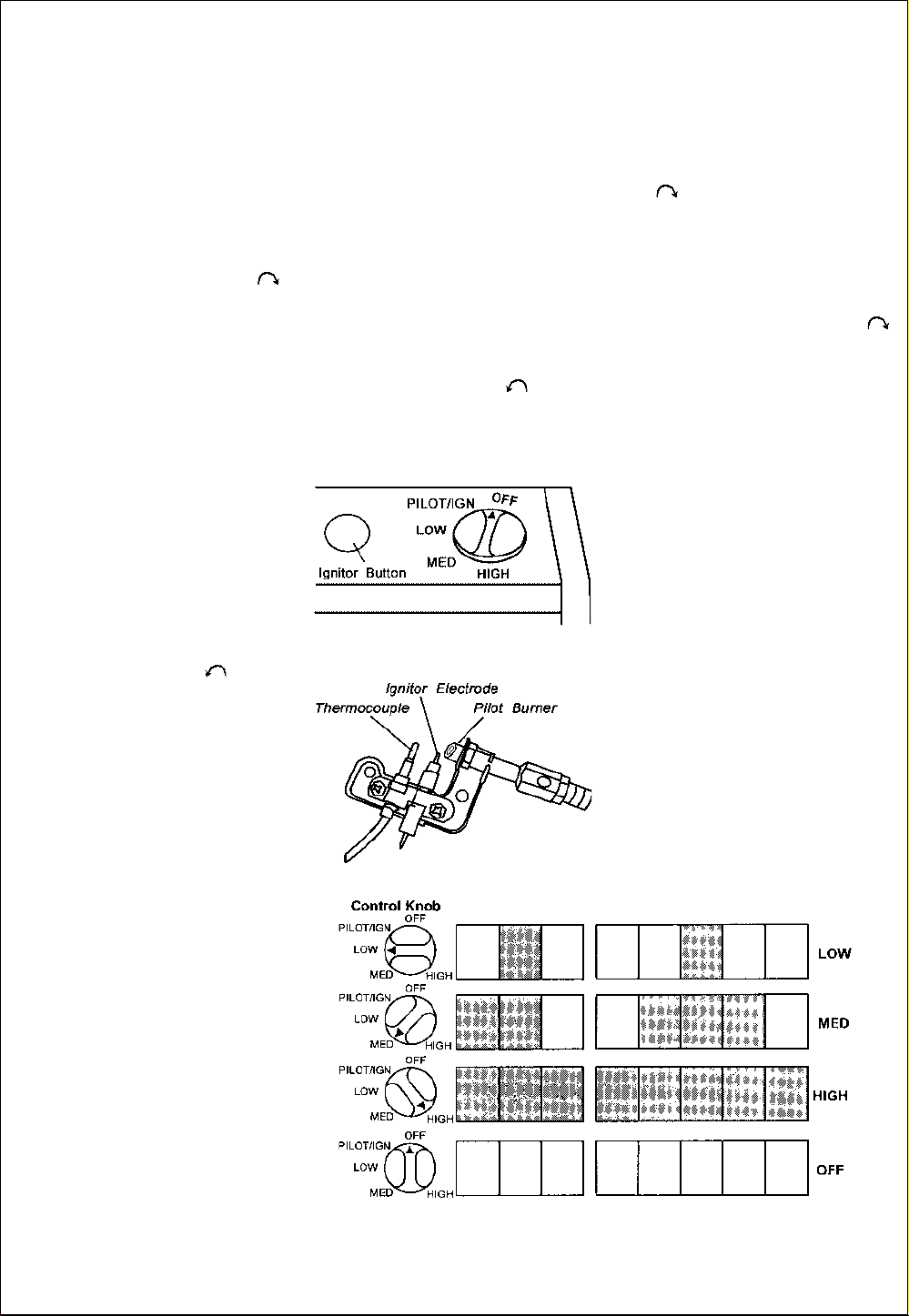
between HI and LO.
Figure 16 - Control Knob In The OFF
Position
to
TO TURN OFF
GAS TO APPLIANCE
Shutting Off Heater
1. Turn control knob clockwise
to the OFF position.
2. Turn off all electric power to
the appliance if service is to
be performed.
SHUTTING OFF BURNER ONLY
(PILOT STA YS LIT)
Turn control knob clockwise
to the PILOT/IGN position.
MANUAL LIGHTING
PROCEDURE
1. Remove lower front panel (see
Figure 7 page 7).
2. Follow steps 1 through 5
under
3. With control knob pressed in,
strike match. Hold match to
pilot until pilot lights.
4. Keep control knob pressed in
for 30 seconds after lighting
pilot. After 30 seconds, release
control knob. Follow step 8
under
5. Replace lower front panel.
Lighting Instructions
Lighting Instructions
.
.
NOTE
: The first time that the
heater is operated after
connecting the gas supply , the
control knob should be depressed
for about thirty (30) seconds. This
will allow air to bleed from the gas
system.
6. With control knob pressed in,
push down and release the
ignitor button. This will light
pilot. If needed, keep pressing
ignitor button until pilot lights.
NOTE
: If pilot does not stay lit,
refer to
14 through 16. Also contact a
qualified service person or gas
supplier for repairs. Until repairs
are made, light pilot with match.
To light pilot with match, see
Troubleshooting
, pages
Manual Lighting Procedure.
Figure 17 - Pilot
Figure 18 - Burner Patterns
11
Page 2
OPERATING YOUR HEATER
THERMOSTAT MODELS
FOR YOUR SAFETY
READ BEFORE LIGHTING
WARNING: If you do not follow
these instructions exactly, a fire or
explosion may result causing
property damage, personal injury or
loss of life.
A. When lighting the pilot, follow
these instructions exactly.
B. BEFORE LIGHTING smell all
around the appliance area for gas.
Be sure to smell next to the floor
because some gas is heavier than
air and will settle on the floor.
WHAT TO DO IF YOU SMELL GAS
Do not try to light any
appliance.
Do not touch any electric
switch; do not use any phone
in your building.
Immediately call your gas
supplier from a neighbor’s
phone. Follow the gas
supplier’s instructions.
if you cannot reach your gas
supplier, call the fire
department.
C. Use only your hand to push in
or turn the gas control knob.
Never use tools. If the knob will
not push in or turn by hand, don’t
try to repair it , call a qualified
service technician or gas supplier.
Force or attempted repair may
result in a fire or explosion.
D. Do not use this appliance if
any part has been under water.
Immediately call a qualified service
technician to inspect the
appliance and to replace any part of
the control system and any gas
control which has been under water.
LIGHTING
INSTRUCTIONS
1. STOP! Read the safety
information on the side of heater.
2. Make sure equipment shutoff
valve is fully open.
3. Turn control knob clockwise
to the OFF position.
4. Wait five(5) minutes to clear
out any gas. Then smell for gas,
including near the floor. If you
smell gas, STOP! Follow "B" in the
safety information on the side of
heater. If you don’t smell
gas, go to the next step.
5. Turn control knob counterclockwise
Press in control knob for five(5)
seconds. (see Figure 19).
Note:
this heater for the first time
after hooking up to gas supply.
If so, the control knob may
need to be pressed in for 30
seconds. This will allow air to
bleed from the gas system.
If control knob does not
pop up when released, contact
a qualified service person or
gas supplier for repairs.
6. With control knob pressed in,
push down and release ignitor
button. This will light pilot. The
pilot is attached to the front of
burner. If needed, keep pressing
ignitor button until pilot lights.
NOTE
to
Troubleshooting
16. Also contact a qualified service
person or gas supplier for repairs.
Until repairs are made, light pilot with
match.To light pilot with match, see
Manual Lighting Procedure
7. Keep control knob pressed
in for 30 seconds after lighting
pilot. After 30 seconds, release
control knob.
If control knob does not
pop up when released, contact
to the PILOT position.
You may be running
: If pilot does not stay lit, refer
, pages 14 through
.
a qualified service person or
gas supplier for repairs.
NOTE
lighting pilot again.
8. Turn control knob
LO.(see Figure 19)
adjust heating levels by using the
equipment shutoff valve.
: If pilot goes out,repeat
steps 3 through 7.This heater
has a safety interlock system.
Wait one(1)minute before
counterclockwise
heating level. The main burner
should light. Set control knob to
any heat level between HI and
CAUTION: Do not try to
to desired
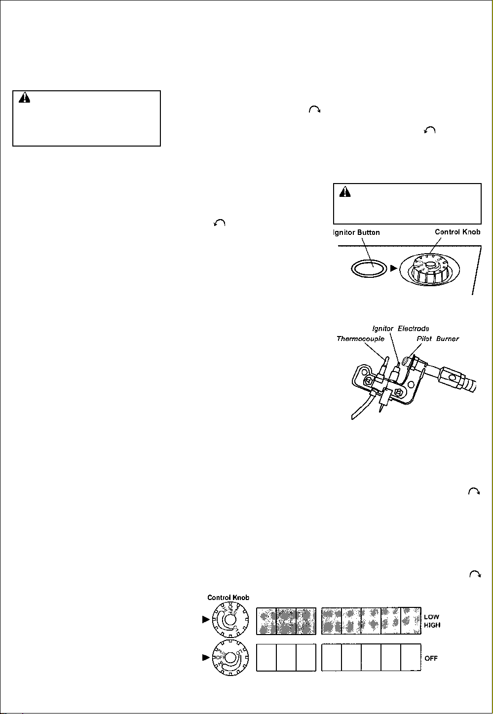
Figure 19 - Control Knob In The
OFF Position
Figure 20 - Pilot
TO TURN OFF
GAS TO APPLIANCE
Shutting Off Heater
1. Turn control knob clockwise
to the OFF position.
2. T urn off all electric power to the
appliance if service is to
be performed.
Shutting Off Burner Only (pilot
stays lit )
Turn control knob clockwise
to the PILOT position.
Figure 21 - Burner Patterns
12
Page 3

OPERATING YOUR HEATER
Continued
THERMOSTAT
CONTROL OPERATION
The thermostatic control used on
these Models differs from standard
thermostats. Standard thermostats
simply turn on and off the burner.
The thermostat used on this heater
senses the room temperature. At
times the room may exceed the set
temperature. If so, the burner will shut
off. The burner will cycle back on
when room temperature drops below
the set temperature. The control
knob can be set to any heat
level between HI and LO.
NOTE
: The thermostat sensing bulb
measures the temperature of air near
the heater cabinet. This may not always agree with room temperature
(depending on housing construction,
installation location, room size, open
air temperatures, etc.)Frequent use of
your heater will let you determine
your own comfort levels.
MANUAL LIGHTING
PROCEDURE
1. Remove lower front panel (see
Figure 7 page 7).
2. Follow steps 1 through 5
under Lighting Instructions on
page 12.
3. With control knob pressed in,
strike match. Hold match to
pilot until pilot lights.
4. Keep control knob pressed in for
30 seconds after lighting pilot. After
30 seconds, release control knob.
Follow step 8 under
Instructions
5. Replace lower front panel.
on page 12.
Lighting
INSPECTING BURNER
Check pilot flame pattern and
burner flame pattern often.
PILOT FLAME PATTERN
Figure 22 shows a correct pilot
flame pattern. Figure 23 shows an
incorrect pilot flame pattern. The
incorrect pilot flame is not touching
thermocouple. This will cause the
thermocouple to cool. When the
thermocouple cools, the heater will
shut down. If pilot flame pattern is
incorrect, as shown in Figure 23.
turn heater off (see T o Turn Of f
Gas To Appliance. page 11 for
non-thermostat models or
page 12 for thermostat models)
see Troubleshooting. pages 14
through 16.
Figure 22 - Correct Pilot Flame
Pattern
Figure 23 - Incorrect Pilot Flame
Pattern
BURNER FLAME P ATTERN
Figure 24 shows a correct burner
flame pattern. Figure 25 shows an
incorrect burner flame pattern. If
burner flame pattem is incorrect,
as shown in Figure 25.
turn heater off (see To T urn Of f
Gas to Appliance. page 11 for
non-thermostat models or page
12 for thermostat models)
see Troubleshooting. pages 14
through 16
Figure 24 - Correct Burner Flame
Pattern
Figure 25 - Incorrect Burner
Flame Pattern
CLEANING AND
MAINTENANCE
WARNING: Turn off heater
and let cool before servicing.
CAUTION: Y ou must keep control
areas, burner, and circulating air
passageways of heater clean. Inspect
these areas of heater before each
use. Have heater inspected yearly by
a qualified service person. Heater may
need more frequent cleaning due to
excessive lint from carpeting, bedding
material, pet hair, etc.
CLEANING ODS/PILOT AND
BURNER
Use a vacuum cleaner,
pressurized air. or a small, soft
bristled brush to clean.
CLEANING BURNER
PILOT AIR INLET HOLE
We recommend that you clean the
unit every 2,500 hours of operation or
every three months. We also
recommend that you keep the burner
tube and pilot assembly clean and
free of dust and dirt. To clean these
parts we recommend using compressed air no greater than 30 PSl.
Your local computer store, hardware store, or home center may
carry compressed air in a can. You
can use a vacuum cleaner in the
blow position. If using compressed
air in a can, please follow the directions on the can. If you don’t follow
directions on the can, you could
damage the pilot assembly.
1. Shut off the unit, including the
pilot. Allow the unit to cool for
at least thirty minutes.
2. Inspect burner, and pilot for dust
and dirt.
3. Blow air through the ports/slots
and holes in the burner.
Also, clean the pilot assembly. A
yellow tip on the pilot flame indicates dust and dirt in the pilot
assembly. There is a small pilot air
inlet hole about two inches from
where the pilot flame comes out of
the pilot assembly (see Figure 26).
With the unit off, lightly blow air
through the air inlet hole. You may
blow through a drinking straw if compressed air is not available.
Figure 26 - Pilot Inlet Air Hole
CLEANING HEA TER CABINET
Air Passageways
Use a vacuum cleaner or
pressurized air to clean.
Exterior
Use a soft cloth dampened with
a mild soap and water mixture.
Wipe the cabinet to remove dust.
13
Page 4

TROUBLESHOOTING
Note :
items are listed in order of
operation.
When ignitor button is pressed and
control knob is pressed in and turned to
the PILOT position, there is no spark
at ODS/pilot.
ODS/pilot lights but flame goes out
when control knob is released.
All troubleshooting
OBSERVED PROBLEM
WARNING: Only a qualified
service person should service and
repair heater.
POSSIBLE CAUSE
1. Ignitor electrode is positioned
wrong.
2. Ignitor electrode is broken.
3. Ignitor electrode is not connected
to ignitor cable.
4. Ignitor cable pinched or wet.
5. Broken ignitor cable.
6. Bad piezo ignitor.
1. Gas supply turned off or
equipment shutoff valve is closed.
2. Control knob not fully pressed in
while pressing ignitor button.
3. Air in gas lines when installed.
4. ODS/pilot is clogged.
5. Gas regulator setting is not correct.
6. Control knob not in PILOT position.
CAUTION: Never use a wire,
needle, or similar object to clean
ODS/pilot. This can damage
ODS/pilot unit.
REMEDY
1. Replace ignitor.
2. Replace ignitor.
3. Reconnect ignitor cable.
4. Free ignitor cable if pinched by
any metal or tubing. Keep
ignitor cable dry.
5. Replace ignitor cable.
6. Replace piezo ignitor.
1. Turn on gas supply of open
equipment shutoff valve.
2. Fully press in control knob
while pressing ignitor button.
3. Continue holding down control
knob. Repeat igniting operation
until air is removed.
4. Clean ODS/pilot (see Cleaning and
Maintenance, Page 13) or
replace ODS/pilot assembly.
5. Replace gas regulator.
6. Turn control knob to PILOT
position.
When ignitor button is pressed and
control knob is press in and turned to
the PILOT position, there is a spark
at ODS/pilot but no ignition.
1. Control knob is not fully pressed
in.
2. Control knob is not pressed in
long enough.
3. Equipment shutoff valve not fully
open.
4. Thermocouple connection loose
at control valve.
5 Pilot flame is not touching
thermocouple, which allows
thermocouple to cool, causing
pilot flame to go out. This
problem could be caused by
one or both of the following:
A) Low gas pressure
B) Dirty or partially clogged
ODS/ pilot
6. Thermocouple damaged.
7. Control valve damaged.
14
1. Press in control knob fully.
2. After ODS/pilot lights, keep control
knob pressed in 30 seconds.
3. Fully open equipment shutoff valve.
4. Hand tighten until snug, then
tighten 1/4 turn more.
5. A) Contact local natural gas
company.
B) Clean ODS/pilot (see Cleaning
and Maintenance, Page 13)
or replace ODS/pilot assembly.
6. Replace thermocouple.
7. Replace control valve.
Page 5

TROUBLESHOOTING
Continued
OBSERVED PROBLEM
Burner(s) does not light after
ODS/pilot is lit.
Delayed ignition of burner(s).
Burner backfiring during combustion.
Burner plaque(s) does not glow.
POSSIBLE CAUSE
1. Burner orifice is clogged.
2. Burner orifice diameter is too small.
3. Inlet gas pressure is too low.
1. Manifold pressure is too low.
2. Burner orifice is clogged.
1. Burner orifice is clogged or
damaged.
2. Burner is damaged.
3. Gas regulator is defective.
1. Plaque is damaged.
2. Inlet gas pressure is too low.
3. Control knob set between locked
positions.
REMEDY
1. Clean burner orifice (see Cleaning
and Maintenance, Page 13) or
replace burner orifice.
2. Replace burner orifice.
3. Contact local natural gas company.
1. Contact local natural gas company.
2. Clean burner (see
Maintenance
burner orifice.
1. Clean burner orifice (see Cleaning
and Maintenance, Page 13) or
replace.
2. Replace burner.
3. Replace gas regulator.
1. Replace burner.
2. Contact local natural gas company.
3. Turn control knob until it locks at
desired setting.
, Page 13) or replace
Cleaning and
Slight smoke or odor during
initial operation.
Heater produces clicking/ticking
noise just after burner is lit or
shut off.
White powder residue forming within
burner box or on adjacent
walls or furniture.
1. Residues from manufacturing
processes.
1. Metal is expanding while heating
or contracting while cooling.
1. When heated the vapors from
furniture polish, wax, carpet
cleaners, etc. turn into white
powder residue.
1. Problem will stop after a few hours
of operation.
1. This is common with most
heaters. if noise is excessive,
contact qualified service person.
1. Turn heater off when using
furniture polish, wax. carpet
cleaner or similar products.
15
Page 6

TROUBLESHOOTING
Continued
WARNING: If you smell gas
Shut off gas supply.
Do not try to light any appliance.
Do not touch any electrical switch; do not use any phone in your building.
Immediately cal l your gas supplier from a neighbor’s phone. Follow the gas
supplier’s instructions.
If you cannot reach your gas supplier, call the fire department.
IMPORTANT
supplies, paint, paint remover, cigarette smoke, cements and glues, new carpet or
textiles, etc., create fumes. These fumes may mix with combustion air and create odors.
OBSERVED PROBLEM
Heater produces unwanted odors.
Heater shuts off in use (ODS operates).
Gas odor even when control knob is
in OFF position.
: Operating heater where impurities in air exist may create odors. Cleaning
POSSIBLE CAUSE
1. Heater burning vapors from
paint, hair spray, glues, etc.
(See IMPORTANT statement
above).
2. Gas leak. See Warning
Statement at top of page.
1. Not enough fresh air is available.
2. Low line pressure.
3. ODS/pilot is partially clogged.
1. Gas leak. See Warning
statement at top of page.
2. Control valve is defective.
REMEDY
1. Ventilate room. Stop using odor
causing products while heater
is running.
2. Locate and correct all leaks(see
Checking Gas Connections,
page 10).
1. Open window and/or door for
ventilation.
2. Contact local natural gas
company.
3. Clean ODS/pilot (see Cleaning
page 13).
1. Locate and correct all leak s(see
Checking Gas Connections,
page 10)
2. Replace control valve.
Gas odor during combustion.
Moisture/condensation noticed on
windows.
1. Foreign matter between control
valve and burner.
2. Gas leak. See Warning
Statement at top of page.
1. Not enough combustion/ventilation
air.
16
1. Take apart gas tubing and
remove foreign matter.
2. Locate and correct all leaks
(see Checking Gas
Connections, page 10).
1. Refer to Air for Combustion and
Ventilation requirements (page
4).
 Loading...