

Empire Vent-Free Log Sets, VFSV-16, VFSR-16, VFSV-18, VFSR-18 Technical Service And Troubleshooting Manual
...
Register Your
Service Manual
Empire Comfort Systems Inc. 918 Freeburg Avenue Belleville, Illinois 62220-2623
618 233-7420 800 851-3153 Fax: 618 233-7097 800 443-8648
Name Date
Company Location
Mailing Address City, ST, ZIP
Phone Fax: E-Mail *
My Company’s Products and Services: (Please check all that apply)
Sell Install Service **
LP Fired Products
Natural Gas Fired Products
Vented Heaters
Vent-Free Heat ers
Vented Hearth
Vent-Free Hearth
Gas Grills
Please List Any Certifications You Currently Hold and the Year Earned:
Your Comments/Suggestions:
* Empire will send Sales Bulletins, Service Bulletins, and other product information to the e-mail
address listed above. If you do not wish to receive these, please check this box.
** Empire’s web sites list servicing companies. If you wish to have your company/location listed,
please provide the service contact information. This information will be published:
Contact Name
Phone E-Mail
Physical Address City, ST, ZIP
(no PO Boxes)
Fax your completed form to Tech Services at 800 443-8648

2

Fireplace Technical Service
And Troubleshooting Manual

TABLE OF CONTENTS
Section Page
Vent Free Fireplace Troubleshooting .....................................................................................1:1
Pilot Flame Characteristics For Vent Free ............................................................................1:12
Clearances And Ventilation For Vent Free ..........................................................................1:14
Direct Vent Fireplace Troubleshooting ...................................................................................2:1
Venting Examples .................................................................................................................2:12
Venting Clearances ...............................................................................................................2:18
Vent Kits ...............................................................................................................................2:21
B Vent Fireplace Troubleshooting ..........................................................................................3:1
Control Valves And Devices ..................................................................................................4:1
Pilot Assemblies (ODS)..........................................................................................................4:2
Gas Valves ..............................................................................................................................4:6
DSI Valves ............................................................................................................................4:16
IP Valves ...............................................................................................................................4:20
RF Valves .............................................................................................................................4:26
Control Device Troubleshooting ..........................................................................................4:32
Sizing Charts ..........................................................................................................................5:1
Service Bullitens.....................................................................................................................6:1
4

Vent Free Fireplace Troubleshooting
Sect1:1

INFORMATION
BULLETIN
NUMBER: 02-1
MODELS: Vent-Free Log Sets
PURPOSE: This is a general information bulletin written to insure the proper installation, application, and use of vent-free log sets.
There are many factors that come into play when there is an occurrence of sooting with any log set. We have compiled the following
informtion to cover any potential issue that can create sooting. Preventative measures taken before initial start up can avoid future
issues with log sets.
IMPORTANT INSTALLATION GUIDELINES
Proper Log Placement
Log placement is critical to proper burner performance. Logs must
be correctly positioned onto the burner. The photos in this manual
show the proper pinned position for logs on this set. Owners need to
be shown proper log placement and instructed not to move the logs.
Logs must t rmly onto the burner when positioned as shown in the
photos. Misformed logs or logs with sloppy holes must be replaced.
Proper Placement of Rock Wool and Decorative Lava Rock
Rock wool can be added to burners for a glowing ember effect. It
must be positioned only on the front portion of the burner. The
photos in this manual show the proper placement of rock wool.
Decorative lava rock or small wood pieces should never be placed
on the burner. These items are only for placement on the oor of the
replace or rebox.
Proper Primary Airow into Burner
For proper burner operation and ame appearance , the ow of
primary air into the venturi tube, located on the rear of the burner,
must not be reduced. This ow of air is reduced if dirt, lint or other
obstructions build-up around or inside the venturi. Any obstruction
in the venturi tube area must be removed. The ow of air into the
venturi is also reduced if the gas orice isn’t centered in the venturi
inlet and/or is not aligned with the venturi. Any misalignment of the
burner orice may be corrected by bending the shutter cap holding
the orice to the inlet of the venturi tube.
Ceiling Fans, Portable Fans or Logs Installed Near Cold Air Returns
Ceiling fans or oscillating oor type fans need to be monitored
during the operation of vent-free logs. If the air blows directly into
the ame causing it to impinge on the log set, or rebox, it should be
turned off or redirected. Ceiling fans could be
reversed to possibly eliminate ame impingement, and the oor
fan could be redirected. Upon installation, be aware of any cold air
returns or vents in the proximity of the log set. Any draft created
around a vent-free log set can cause the ame to impinge on the log
and create a sooting situation.
Candles
Avoid the use of scented or decorative candles while the log set
is in operation. Candles produce a residue in the air that creates a
soot like substance. Burning candles while the log set is operating
magnies the problem. It should be noted that candles, in general
produce soot. The amount of time burned and the quantity of
candles burned will determine the amount of soot produced and
deposited.
Make Owners Aware of Proper Log Set Operation
Properly installed and properly maintained log sets do not deposit
soot on the logs. If users see soot appear on a log, call for service.
Do not continue to operate the log set.
Sunken Fireplace
If installing this unit into a sunken replace, you must raise the oor
to insure adequate airow and guard against sooting. Raise replace
oor using a non-combustible material, which is secure.
Glass Doors
Make sure that glass doors are open during all operations of the
logset. The opening of the glass door frame should be the dimension
used for the minumum front opening of the rebox.
Woodburning Fireplaces
The interior of the rebox and the chimney should be cleared and
free of all creosote before installing a gas burning log set. Creosote
will soften when heated and can drop on the log set casuing odors
and possible sooting.
Empire Comfort Systems Inc. 918 Freeburg Avenue Belleville, Illinois 62222-0529
Sect1:2
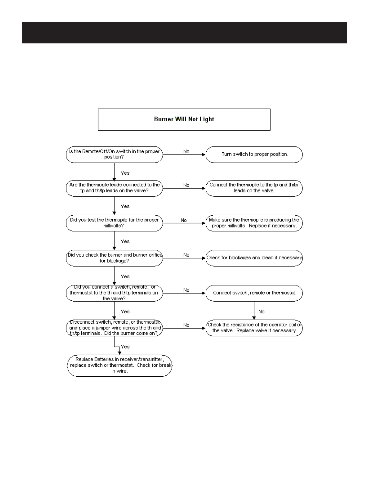
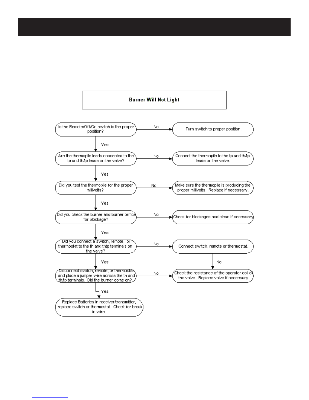
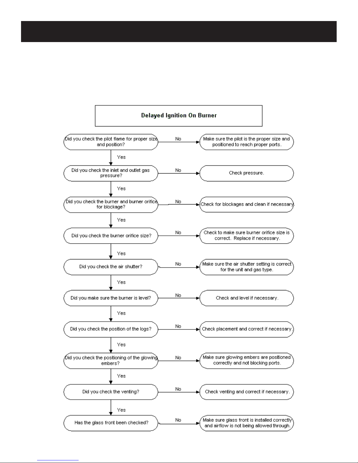
DIAGNOSING VENT FREE FIREPLACES
Sect1:3
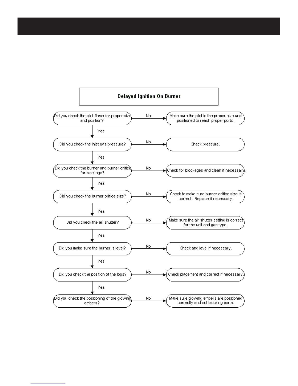
DIAGNOSING VENT FREE FIREPLACES
Sect1:4
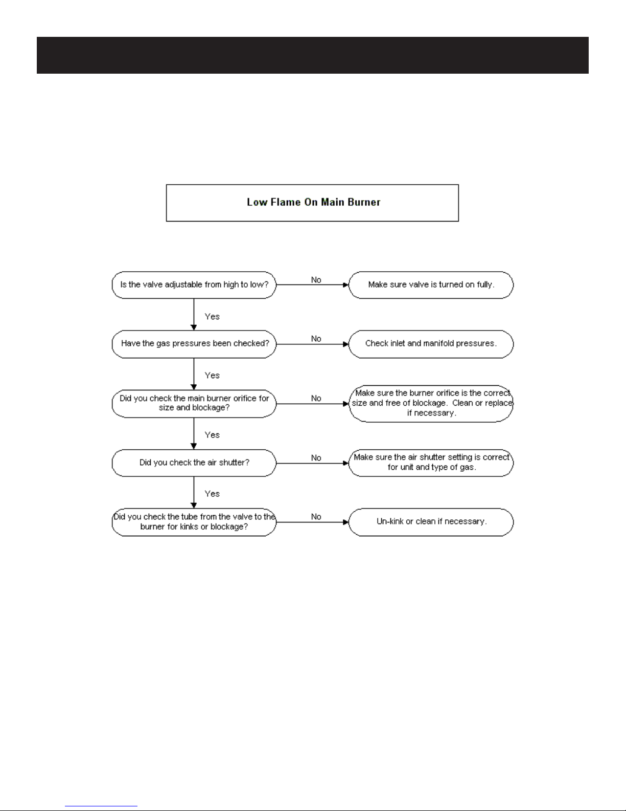
DIAGNOSING VENT FREE FIREPLACES
Sect1:5
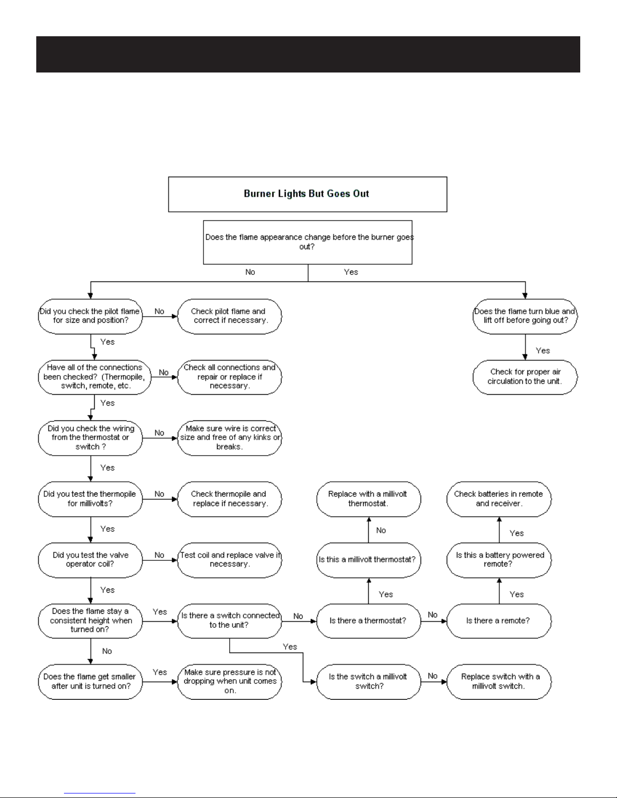
DIAGNOSING VENT FREE FIREPLACES
Sect1:6
DIAGNOSING VENT FREE FIREPLACES
Sect1:7
DIAGNOSING VENT FREE FIREPLACES
Sect1:8
DIAGNOSING VENT FREE FIREPLACES
Sect1:9
DIAGNOSING VENT FREE FIREPLACES
Sect1:10
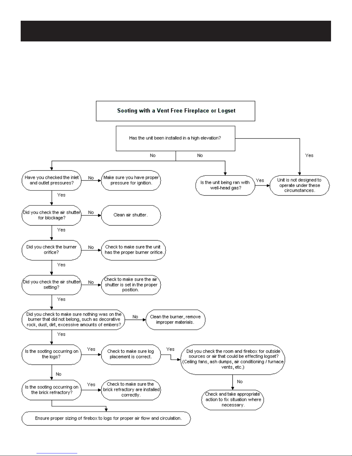
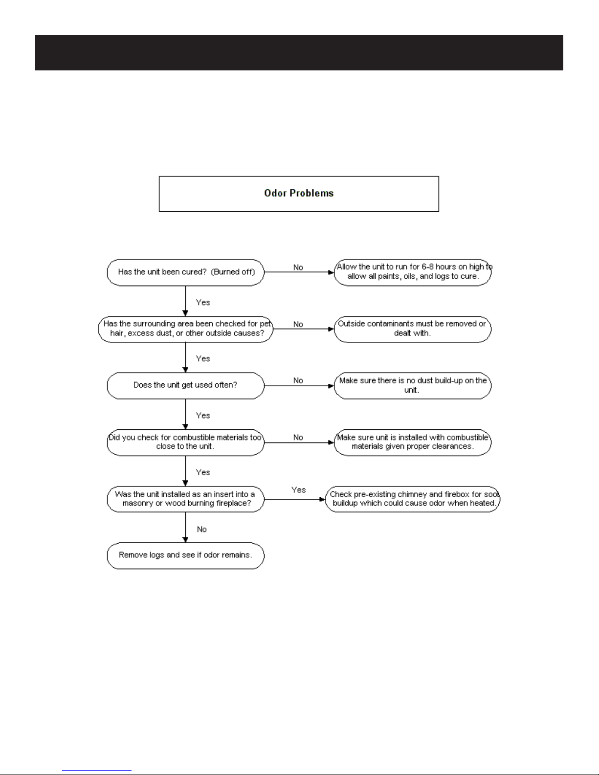
SOOTING CAUSES
Sect1:11
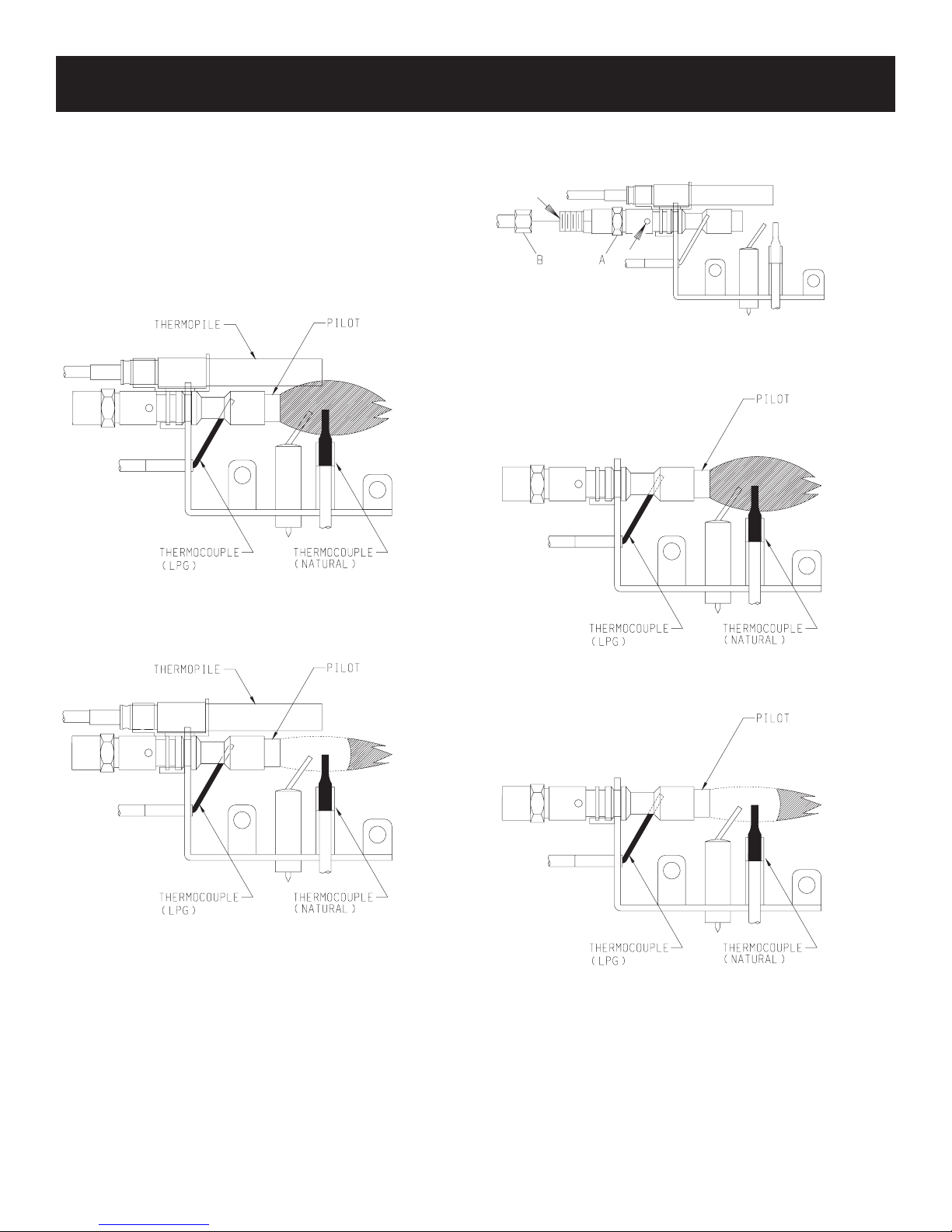
PILOT FLAME CHARACTERISTICS
Figures 1 and 4 show a correct pilot ame pattern. The correct
ame will be blue and will extend beyond the thermocouple. The
ame will surround the thermocouple just below the tip. A slight
yellow ame may occur where the pilot ame and main burner
ame meet. Figures 2 and 5 show an incorrect pilot ame pattern.
The incorrect pilot ame is not touching the thermocouple. This
will cause the thermocouple to cool. When the thermocouple cools,
the heater will shut down.
VFSR PILOT
2. Blow air pressure through the holes indicated by the arrows.
This will blow out foreign materials such as dust, lint and spider
webs. Tighten nut B also by grasping nut A.
Figure 3
VFSV PILOT
Correct appearance of pilot ame.
Figure 1
Incorrect appearance of pilot ame.
Figure 2
If pilot ame pattern is incorrect, as shown in Figure 2
• See Troubleshooting, page 1:13.
Cleaning and Maintenance/Pilot
Oxygen Depletion Sensor Pilot (Figure 3 )
When the pilot has a large yellow tip ame, clean the Oxygen
Depletion Sensor as follows:
1. Clean the ODS pilot by loosening nut B from the pilot tubing.
When this procedure is required, grasp nut A with an open end
wrench.
Correct Pilot Flame Pattern
Figure 4
Incorrect Pilot Flame Pattern
Figure 5
If pilot ame pattern is incorrect, as shown in Figure 5
• See Troubleshooting, page 1:13.
Sect1:12

TROUBLESHOOTING
SYMPTOMS - POSSIBLE CAUSES AND CORRECTION
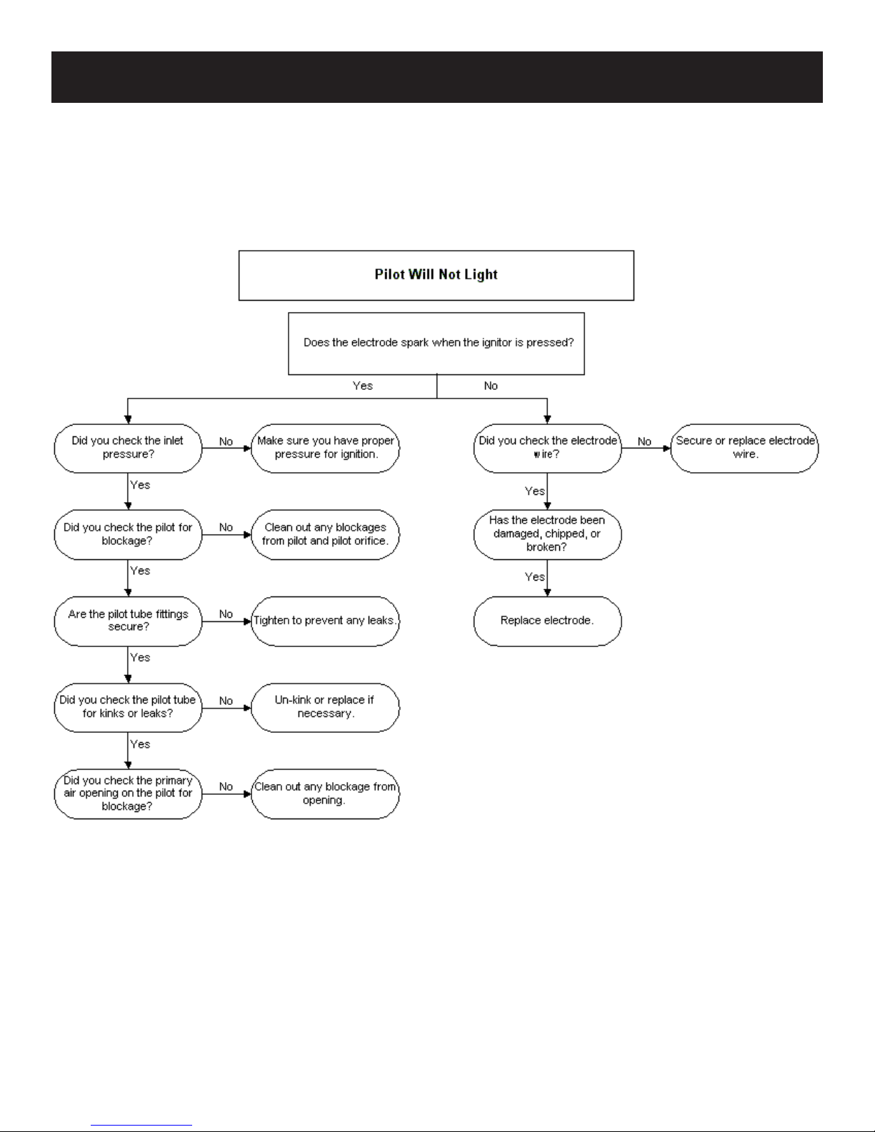
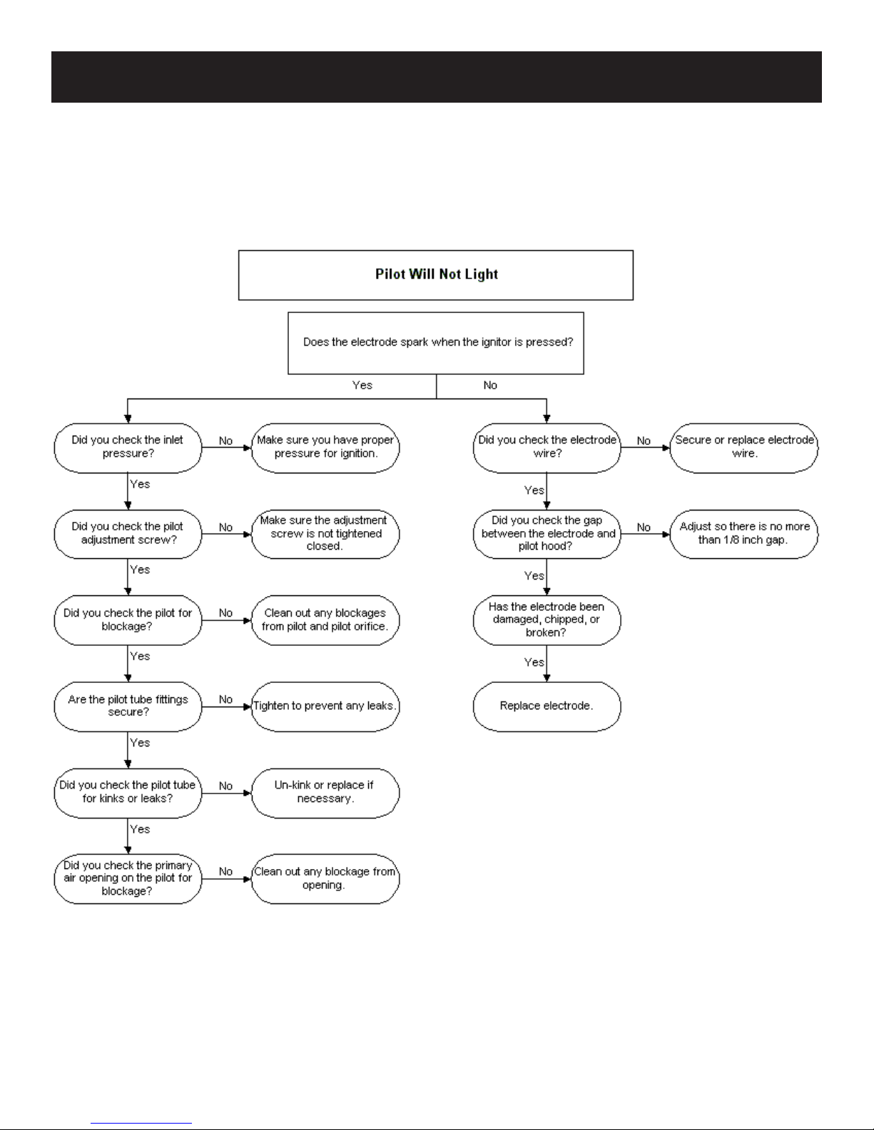
1. When ignitor button is pressed, there is no spark at ODS/
pilot.
a. Ignitor electrode positioned wrong - Replace pilot.
b. Ignitor electrode is broken - Replace pilot.
c. Ignitor electrode not connected to ignitor cable - Reconnect
ignitor cable.
d. Ignitor cable pinched or wet. Keep ignitor cable dry - Free
ignitor cable if pinched by any metal or tubing.
e. Broken ignitor cable - Replace ignitor cable.
f. Bad piezo ignitor - Replace piezo ignitor.
2. Appliance produces unwanted odors.
a. Appliance burning vapors from paint, hair spray, glues,
etc. - Ventilate room. Stop using odor causing products
while heater is running.
b. Gas leak - Locate and correct all leaks.
3. Appliance shuts off during use. (Pilot and main burner are
off.)
a. Not enough fresh air is available for ODS/pilot to operate
- Open window and/or door for ventilation.
b. Low line pressure - Contact local gas company.
c. ODS/pilot is partially clogged - Clean ODS/pilot.
d. Defective thermocouple - Replace pilot.
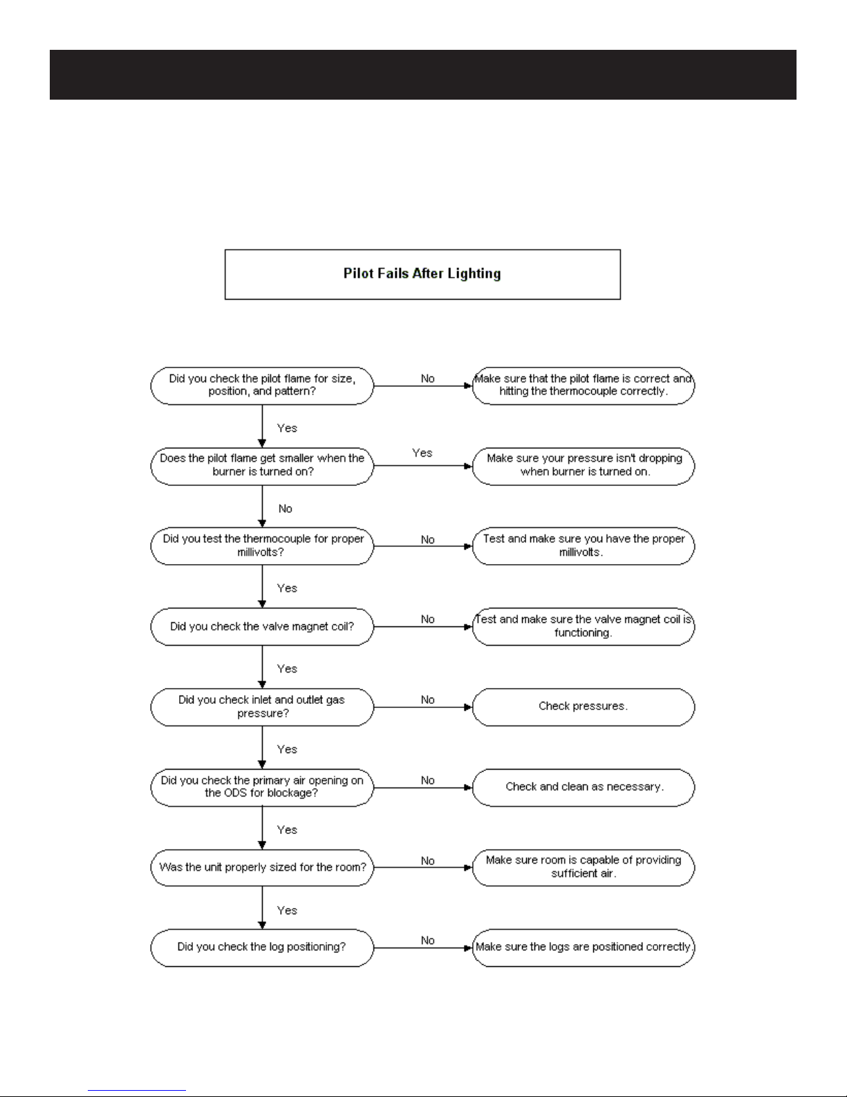
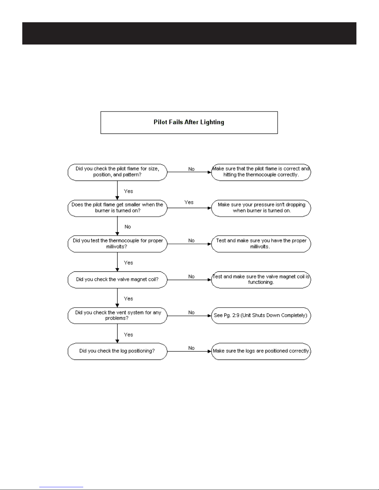
4. Appliance shuts off during use. (Pilot stays on.)
a. Low line pressure - Check line pressure to the valve.
b. Defective thermopile - Check pilot ame, check wire
connections, output should be a minimum of 325 millivolts
across. TH/TP and TP terminals with ON/OFF switch
off.
5. Gas odor even when control knob is in OFF position.
a. Gas leak - Locate and correct all leaks.
b. Control valve defective - Replace control valve.
6. When ignitor button is pressed, there is spark at ODS/pilot,
but no ignition.
a. Gas supply turned off or manual shutoff valve closed - Turn
on gas supply or open manual shutoff valve.
b. Control knob not in PILOT position - Turn control knob
to PILOT position.
c. Control knob not pressed in while in PILOT position - Press
in control knob while in PILOT position.
d. Air in gas lines when installed - Continue holding down
control knob. Repeat igniting operation until air is
removed.
e. ODS/pilot is clogged - Replace ODS/pilot assembly or get
it serviced.
g. Gas regulator setting is not correct - Replace gas
regulator.
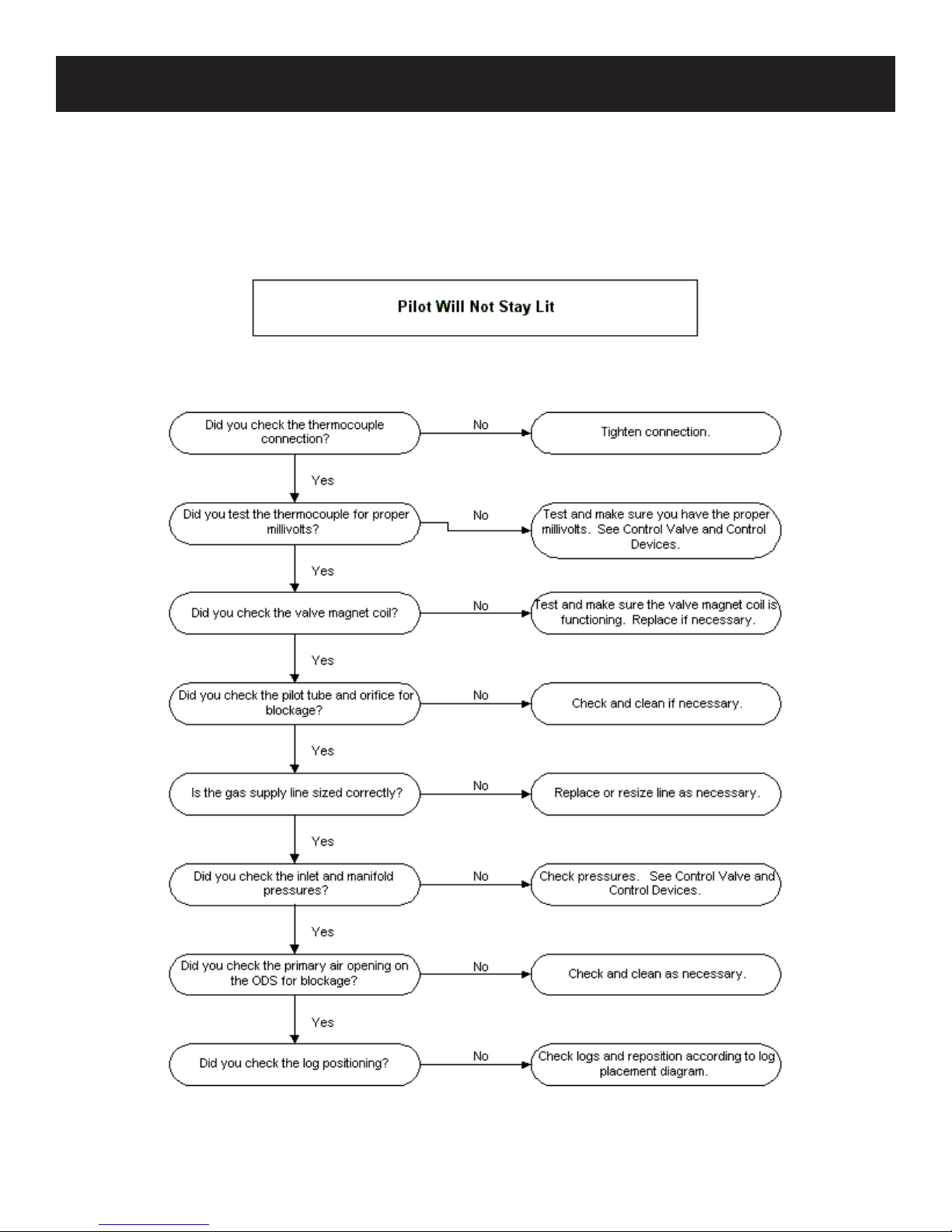
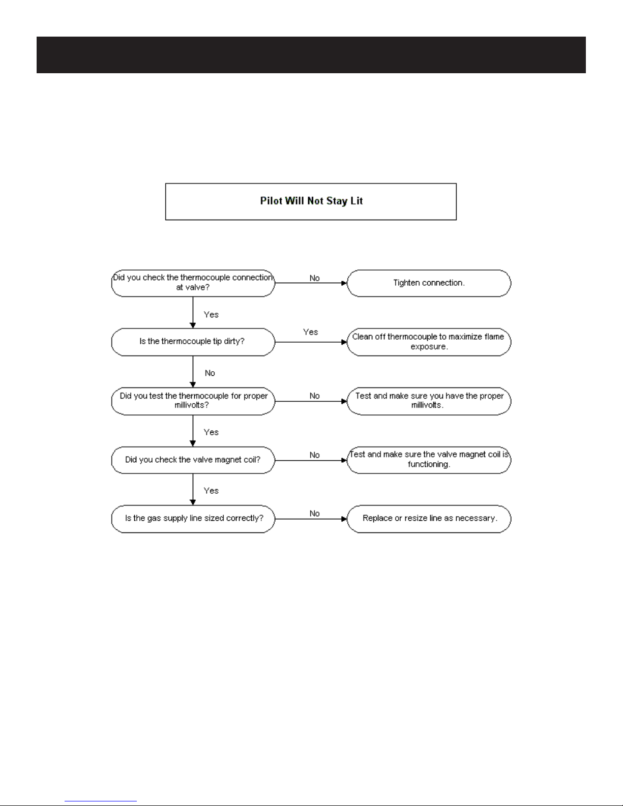
7. ODS/pilot lights but ame goes out when control knob is
released.
a. Control knob not fully pressed in - Press in control knob
fully.
b. Control knob not pressed in long enough - After ODS/pilot
lights, keep control knob pressed in 30 seconds.
c. Manual Shutoff valve not fully open - Fully open manual
shutoff valve.
d. Thermocouple connection loose at control valve - Hand
tighten until snug, then tighten 1/4 turn more.
e. Pilot ame not touching thermocouple, which allows
thermocouple to cool, causing pilot ame to go out. This
problem could be caused by either low gas pressure or
dirty or partially clogged ODS/pilot - Contact local gas
company.
f. Thermocouple damaged - Replace thermocouple.
h. Control valve damaged - Replace control valve.
8. Burner does not light after ODS/pilot is lit.
a. Burner orice clogged - Clean burner or replace main burner
orice.
b. Burner orice diameter is too small - Replace burner
orice.
c. Inlet gas pressure is too low - Contact qualied service
person.
9. If burning at main burner orice occurs (a loud, roaring
blow torch noise).
a. You must turn off burner assembly and contact a qualied
service person.
b. Manifold pressure is too low - Contact local gas
company.
c. Burner orice clogged - Clean burner or replace burner
orice.
10. Logs appear to smoke after initial operation.
a. Vapors from paint or curing process of logs - Problem will
stop after a few hours of operation. Run the heater with the
damper open if you have one, or open a window for the
rst few hours.
Log heater is intended to be smokeless. Turn OFF heater
and call qualied service person.
11. Heater produces a whistling noise when main burner is
lit.
a. Turning control knob to HIGH position when main burner
is cold - Turn control knob to LOW position and let warm
up for a minute.
b. Air in gas line - Operate burner until air is removed from
line. Have gas line checked by local gas company.
c. Dirty or partially clogged burner orice - Clean burner or
replace burner orice.
12. No gas to pilot.
a. LP-regulator shut down due to inlet pressure too high -
Verify LP tank regulator is installed and set at 11" to 13"
w.c. Replace regulator on heater.
13. New Installation.
a. On VFSV Model variable does not operate-On is OFF/OFF
is ON-wires into the back of receiver are reversed.
If the gas quality is bad, your pilot may not stay lit, the burners may produce soot and the heater may backre when lit. If the gas quality or
pressure is low, contact your local gas supplier immediately.
Sect1:13
PROVISIONS FOR ADEQUATE COMBUSTION & VENTILATION AIR
This heater shall not be installed in a conned space unless provisions are
provided for adequate combustion and ventilation air.
The National Fuel Gas Code denes a conned space as a space whose
volume is less than 50 cubic feet per 1,000 Btu per hour (4.8m3 per kw) of
the aggregate input rating of all appliances installed in that space and an
unconned space as a space whose volume is not less than 50 cubic feet
per 1,000 Btu per hour (4.8 m3 per kw) of the aggregate input rating of all
appliances installed in that space. Rooms communicating directly with the
space in which the appliances are installed, through openings not furnished
with doors, are considered a part of the unconned space.
Unusually Tight Construction
The air that leaks around doors and windows may provide enough fresh
air for combustion and ventilation. However, in buildings of unusually
tight construction, you must provide additional fresh air.
Unusually tight construction is dened as construction where:
a. Walls and ceilings exposed to the outside atmosphere have a con-
tinuous water vapor retarder with a rating of one perm or less with
openings gasketed or sealed, and
b. Weatherstripping has been added on openable windows and doors,
and
c. Caulking or sealants are applied to areas such as joints around
window and door frames, between sole plates and oors, between
wall-ceiling joints, between wall panels, at penetrations for plumb-
ing, electrical, and gas lines, and at other openings.
If your home meets all of the three criteria above, you must provide
additional fresh air.
Warning: If the area in which the heater may be operated is smaller than
that dened as an unconned space or if the building is of unusually tight
construction, provide adequate combustion and ventilation air by one of
the methods described in the National Fuel Gas Code, ANSI Z223.1/NFPA
54, Air for Combustion and Ventilation, or applicable local codes.
The following formula can be used to determine the maximum heater
rating per the denition of unconned space:
If the area in which the heater may be operated is smaller than that dened
as an unconned space, provide adequate combustion and ventilation air
by one of the methods described in the National Fuel Gas Code, ANSI
Z223.1, NFPA54.
Adhere to all codes, or in their absence, the latest edition of THE
NATIONAL FUEL GAS CODE ANSI Z223.1/NFPA54 which can be
obtained from:
American National Standards Institute National Fire Protection Association, Inc.
11 West 42nd St. Batterymarch Park
New York, NY 10018 Quincy, MA 02269
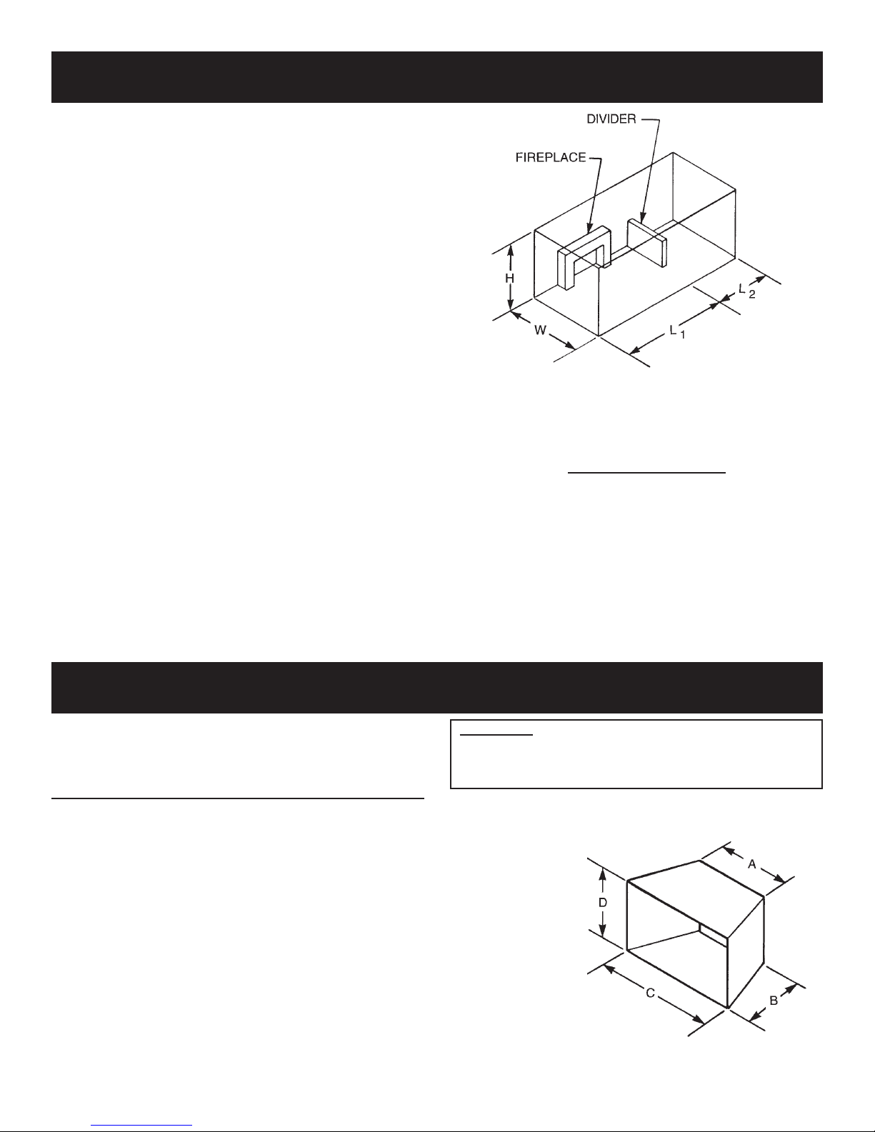
Example of Large Room with 1/2 Wall divider.
Figure 7
Btu/Hr =
(L1 + L2)FT x (W)FT x (H)FT
50
x 1000
CLEARANCES
Minimum Dimensions For Solid Fuel Burning Fireplaces
UL127 Factory Built Fireplaces (Figure 8)
Model A B C D
VFSV-16 18" 11 1/2" 24" 18"
VFSR-16 18" 11 1/2" 24" 18"
VFSV-18 17" 14" 28" 17"
VFSR-18 17" 14" 28" 17"
VFSM-18 21" 14" 32" 17"
VFSV-24 23" 14" 30" 18"
VFSR-24 23" 14" 30" 18"
VFSM-24 27" 14" 34" 18"
VFSV-30 26" 14" 34" 20"
VFSR-30 26" 14" 34" 20"
VFSM-30 30" 14" 38" 20"
The dimensions shown and dened in the replace manufacturer’s
instructions are minimum clearances to maintain in installing this
heater. Left and right clearances are determined when facing the
front of the heater.
Glass Doors
Make sure that glass doors are open during all operations of
the logset. The opening of the glass door frame should be the
dimension used for the minimum front opening of the rebox.
Follow these instructions to ensure safe installation.
Failure to follow instructions
exactly can create a
re hazard.
Figure 8
Sect1:14

PILOT FLAME CHARACTERISTICS (continued)
Cleaning and Maintenance/Pilot
Oxygen Depletion Sensor Pilot (Figure 6)
When the pilot has a large yellow tip ame, clean the Oxygen
Depletion Sensor as follows:
1. Clean the ODS pilot by loosening nut B from the pilot tubing.
When this procedure is required, grasp nut A with an open end
wrench.
2. Blow air pressure through the holes indicated by the arrows.
This will blow out foreign materials such as dust, lint and spider
webs. Tighten nut B also by grasping nut A.
CLEANING AND SERVICING
Annual inspection and cleaning by your dealer or qualied
service technician is recommended to prevent malfunction
and/or sooting.
TURN OFF HEATER AND ALLOW TO COOL BEFORE
CLEANING.
Remove logs, handling carefully by holding gently at each end.
Gloves are recommended to prevent skin irritation from ceramic
bers. If skin becomes irritated, wash gently with soap and water.
Refer to manual for correct log placement.
PERIODIC CLEANING – Refer to parts diagram for location
of items discussed below.
• Do not use cleaning uid to clean logs or any part of heater.
• Logs - brush with soft bristle brush or vacuum with brush
attachment.
• Remove loose particles and dust from the burner areas,
controls, piezo covers and grate. Don’t remove crushed media
from inside burner box.
• Inspect and clean burner air intake holes. Remove lint or
particles with brush. Failure to keep air intake holes clean will
result in sooting and poor combustion.
Warning:
Never use needles, wires, or similar cylindrical objects to
clean the pilot to avoid damaging the calibrated ruby that
controls the gas ow.
Figure 6
ANNUAL CLEANING/INSPECTION – Refer to parts diagram
for location of items discussed below.
• Inspect and clean rear burner air intake holes. Remove lint or
particles with vacuum or brush. Failure to keep air intake
holes clean will result in sooting and poor combustion.
• Inspect and clean all burner ports.
• Inspect ODS pilot for operation and accumulation of lint at air
intake holes.
• Verify ame pattern and log placement for proper operation.
• Verify smooth and responsive ignition of main burner.
• Check level of glass media in burner. Burner should be full,
up to the level of openings in burner top.
Attention: Ceramic media that is dislodged from burner box
during shipment can be replaced through openings in burner
top. If settling of ceramic media occurs during shipment an
additional bag of ceramic media, part number, 12389 can be
ordered from Empire Comfort Systems, Inc.
Sect1:15
PLACEMENT OF GLOWING EMBERS AND LAVA ROCK
Placement of the glowing embers (rock wool) is very individual
and light coverage will provide your best effects. We recommend
separation of the rock wool by hand and make your coverage as
light and uffy as possible.
Place just enough embers on the burner to obtain the glow and a
gold, yellow ame.
Do not place embers (rock wool) over large ports in rear portion
of burner.
Rock wool should not be placed in the area of the pilot assembly.
Replacement of loose material (glowing embers) must be purchased
from Empire Comfort Systems, Inc. Application of excess loose
material (glowing embers) may adversely affect performance of
the heater. WARNING: All previously applied loose material must
be removed prior to reapplication.
Refer to Parts List in owners manual to order loose material (rock
wool).
Placing Lava Rock in Front of Burner on Fireplace Floor
Spread lava rocks on replace oor in front of the burner pan.
The lava rocks are for decorative effect and are not required for
replace operation.
ATTENTION: DO NOT PLACE LAVA ROCKS ON BURNER, LOGS OR ROCK WOOL. THE LAVA ROCKS SHOULD
ONLY BE PLACED ON THE FIREPLACE FLOOR.
FIREPLACE PREPARATION
• Turn off gas supply to replace or rebox.
• Have the replace oor and chimney professionally cleaned to remove
ashes, soot, creosote or other obstructions.
Have this cleaning performed annually after installation.
• Seal any fresh air vents or ash clean-out doors located on oor or wall
of replace. If not, drafting may cause pilot
outage or sooting. Use a heat-resistant sealant. Do not seal chimney
ue damper.
Install and operate the appliance as directed in this manual.
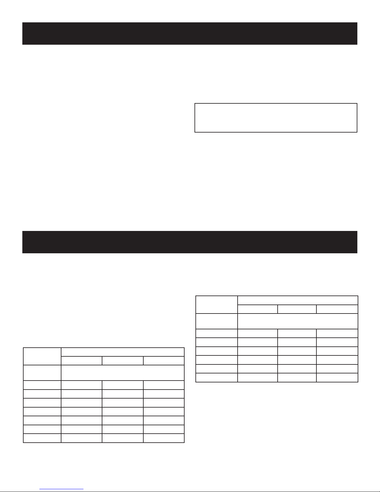
FOR FACTORY BUILT FIREPLACES
FREE OPENING AREA OF CHIMNEY DAMPER FOR VENTING
COMBUSTION PRODUCTS FROM DECORATIVE APPLIANCES
FOR INSTALLATION IN SOLID FUEL BURNING FIREPLACES
Appliance Input Rate (BTU/hr)
20 30 40
Chimney
Height* (ft)
10 11.3 16.6 22.1
15 8.6 12.6 17.3
20 7.5 10.8 14.5
25 6.6 9.6 12.6
30 6.2 9.1 11.3
35 5.7 8.0 10.8
40 5.3 7.5 10.2
* Height is from hearth to top of chimney and the minimum height
is 10 feet.
** Chart shows minimum opening (sq. in.) for given height and input
rate.
Minimum Opening** (sq. in.)
FOR MASONRY BUILT FIREPLACES
FREE OPENING AREA OF CHIMNEY DAMPER FOR VENTING
COMBUSTION PRODUCTS FROM DECORATIVE APPPLIANCES
FOR INSTALLATION IN SOLID FUEL BURNING FIREPLACES
Appliance Input Rate (BTU/hr)
20 30 40
Chimney
Height* (ft)
6 17.6 25.7 33.8
8 16.5 23.7 31.2
10 15.1 21.7 28.7
15 14.1 19.9 26.1
20 12.9 18.5 23.7
30 12.2 16.9 21.6
* Height is from hearth to top of chimney and the minimum height is
6 feet.
** Chart shows minimum opening (sq. in.) for given height and input
rate.
Minimum Opening** (sq. in.)
Sect1:16

Sect1:17

SERVICE NOTES
Sect1:18

SERVICE NOTES
Sect1:19

Sect1:20

Direct Vent Fireplace
Troubleshooting
Sec2:1
DIAGNOSING DIRECT VENT FIREPLACES
Sec2:2
DIAGNOSING DIRECT VENT FIREPLACES
Sec2:3
DIAGNOSING DIRECT VENT FIREPLACES
Sec2:4
DIAGNOSING DIRECT VENT FIREPLACES
Sec2:5
DIAGNOSING DIRECT VENT FIREPLACES
Sec2:6
 Loading...