

Empire Vent-Free Log Sets, VFSV-16, VFSR-16, VFSV-18, VFSR-18 Technical Service And Troubleshooting Manual
...Page 1
Register Your
Service Manual
Empire Comfort Systems Inc. 918 Freeburg Avenue Belleville, Illinois 62220-2623
618 233-7420 800 851-3153 Fax: 618 233-7097 800 443-8648
Name Date
Company Location
Mailing Address City, ST, ZIP
Phone Fax: E-Mail *
My Company’s Products and Services: (Please check all that apply)
Sell Install Service **
LP Fired Products
Natural Gas Fired Products
Vented Heaters
Vent-Free Heat ers
Vented Hearth
Vent-Free Hearth
Gas Grills
Please List Any Certifications You Currently Hold and the Year Earned:
Your Comments/Suggestions:
* Empire will send Sales Bulletins, Service Bulletins, and other product information to the e-mail
address listed above. If you do not wish to receive these, please check this box.
** Empire’s web sites list servicing companies. If you wish to have your company/location listed,
please provide the service contact information. This information will be published:
Contact Name
Phone E-Mail
Physical Address City, ST, ZIP
(no PO Boxes)
Fax your completed form to Tech Services at 800 443-8648
Page 2

2
Page 3

Fireplace Technical Service
And Troubleshooting Manual
Page 4

TABLE OF CONTENTS
Section Page
Vent Free Fireplace Troubleshooting .....................................................................................1:1
Pilot Flame Characteristics For Vent Free ............................................................................1:12
Clearances And Ventilation For Vent Free ..........................................................................1:14
Direct Vent Fireplace Troubleshooting ...................................................................................2:1
Venting Examples .................................................................................................................2:12
Venting Clearances ...............................................................................................................2:18
Vent Kits ...............................................................................................................................2:21
B Vent Fireplace Troubleshooting ..........................................................................................3:1
Control Valves And Devices ..................................................................................................4:1
Pilot Assemblies (ODS)..........................................................................................................4:2
Gas Valves ..............................................................................................................................4:6
DSI Valves ............................................................................................................................4:16
IP Valves ...............................................................................................................................4:20
RF Valves .............................................................................................................................4:26
Control Device Troubleshooting ..........................................................................................4:32
Sizing Charts ..........................................................................................................................5:1
Service Bullitens.....................................................................................................................6:1
4
Page 5

Vent Free Fireplace Troubleshooting
Sect1:1
Page 6

INFORMATION
BULLETIN
NUMBER: 02-1
MODELS: Vent-Free Log Sets
PURPOSE: This is a general information bulletin written to insure the proper installation, application, and use of vent-free log sets.
There are many factors that come into play when there is an occurrence of sooting with any log set. We have compiled the following
informtion to cover any potential issue that can create sooting. Preventative measures taken before initial start up can avoid future
issues with log sets.
IMPORTANT INSTALLATION GUIDELINES
Proper Log Placement
Log placement is critical to proper burner performance. Logs must
be correctly positioned onto the burner. The photos in this manual
show the proper pinned position for logs on this set. Owners need to
be shown proper log placement and instructed not to move the logs.
Logs must t rmly onto the burner when positioned as shown in the
photos. Misformed logs or logs with sloppy holes must be replaced.
Proper Placement of Rock Wool and Decorative Lava Rock
Rock wool can be added to burners for a glowing ember effect. It
must be positioned only on the front portion of the burner. The
photos in this manual show the proper placement of rock wool.
Decorative lava rock or small wood pieces should never be placed
on the burner. These items are only for placement on the oor of the
replace or rebox.
Proper Primary Airow into Burner
For proper burner operation and ame appearance , the ow of
primary air into the venturi tube, located on the rear of the burner,
must not be reduced. This ow of air is reduced if dirt, lint or other
obstructions build-up around or inside the venturi. Any obstruction
in the venturi tube area must be removed. The ow of air into the
venturi is also reduced if the gas orice isn’t centered in the venturi
inlet and/or is not aligned with the venturi. Any misalignment of the
burner orice may be corrected by bending the shutter cap holding
the orice to the inlet of the venturi tube.
Ceiling Fans, Portable Fans or Logs Installed Near Cold Air Returns
Ceiling fans or oscillating oor type fans need to be monitored
during the operation of vent-free logs. If the air blows directly into
the ame causing it to impinge on the log set, or rebox, it should be
turned off or redirected. Ceiling fans could be
reversed to possibly eliminate ame impingement, and the oor
fan could be redirected. Upon installation, be aware of any cold air
returns or vents in the proximity of the log set. Any draft created
around a vent-free log set can cause the ame to impinge on the log
and create a sooting situation.
Candles
Avoid the use of scented or decorative candles while the log set
is in operation. Candles produce a residue in the air that creates a
soot like substance. Burning candles while the log set is operating
magnies the problem. It should be noted that candles, in general
produce soot. The amount of time burned and the quantity of
candles burned will determine the amount of soot produced and
deposited.
Make Owners Aware of Proper Log Set Operation
Properly installed and properly maintained log sets do not deposit
soot on the logs. If users see soot appear on a log, call for service.
Do not continue to operate the log set.
Sunken Fireplace
If installing this unit into a sunken replace, you must raise the oor
to insure adequate airow and guard against sooting. Raise replace
oor using a non-combustible material, which is secure.
Glass Doors
Make sure that glass doors are open during all operations of the
logset. The opening of the glass door frame should be the dimension
used for the minumum front opening of the rebox.
Woodburning Fireplaces
The interior of the rebox and the chimney should be cleared and
free of all creosote before installing a gas burning log set. Creosote
will soften when heated and can drop on the log set casuing odors
and possible sooting.
Empire Comfort Systems Inc. 918 Freeburg Avenue Belleville, Illinois 62222-0529
Sect1:2
Page 7
DIAGNOSING VENT FREE FIREPLACES
Sect1:3
Page 8
DIAGNOSING VENT FREE FIREPLACES
Sect1:4
Page 9
DIAGNOSING VENT FREE FIREPLACES
Sect1:5
Page 10
DIAGNOSING VENT FREE FIREPLACES
Sect1:6
Page 11
DIAGNOSING VENT FREE FIREPLACES
Sect1:7
Page 12
DIAGNOSING VENT FREE FIREPLACES
Sect1:8
Page 13
DIAGNOSING VENT FREE FIREPLACES
Sect1:9
Page 14
DIAGNOSING VENT FREE FIREPLACES
Sect1:10
Page 15
SOOTING CAUSES
Sect1:11
Page 16
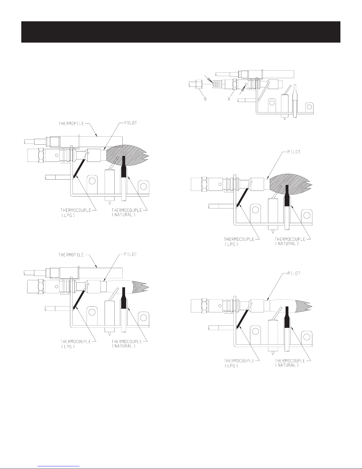
PILOT FLAME CHARACTERISTICS
Figures 1 and 4 show a correct pilot ame pattern. The correct
ame will be blue and will extend beyond the thermocouple. The
ame will surround the thermocouple just below the tip. A slight
yellow ame may occur where the pilot ame and main burner
ame meet. Figures 2 and 5 show an incorrect pilot ame pattern.
The incorrect pilot ame is not touching the thermocouple. This
will cause the thermocouple to cool. When the thermocouple cools,
the heater will shut down.
VFSR PILOT
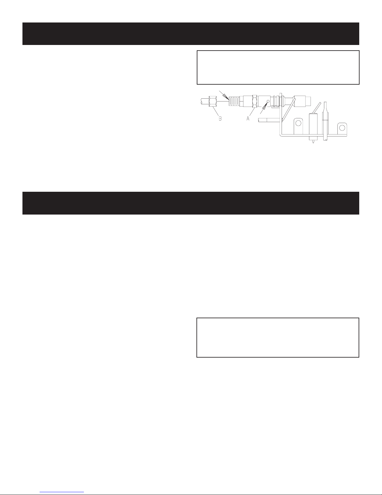
2. Blow air pressure through the holes indicated by the arrows.
This will blow out foreign materials such as dust, lint and spider
webs. Tighten nut B also by grasping nut A.
Figure 3
VFSV PILOT
Correct appearance of pilot ame.
Figure 1
Incorrect appearance of pilot ame.
Figure 2
If pilot ame pattern is incorrect, as shown in Figure 2
• See Troubleshooting, page 1:13.
Cleaning and Maintenance/Pilot
Oxygen Depletion Sensor Pilot (Figure 3 )
When the pilot has a large yellow tip ame, clean the Oxygen
Depletion Sensor as follows:
1. Clean the ODS pilot by loosening nut B from the pilot tubing.
When this procedure is required, grasp nut A with an open end
wrench.
Correct Pilot Flame Pattern
Figure 4
Incorrect Pilot Flame Pattern
Figure 5
If pilot ame pattern is incorrect, as shown in Figure 5
• See Troubleshooting, page 1:13.
Sect1:12
Page 17

TROUBLESHOOTING
SYMPTOMS - POSSIBLE CAUSES AND CORRECTION
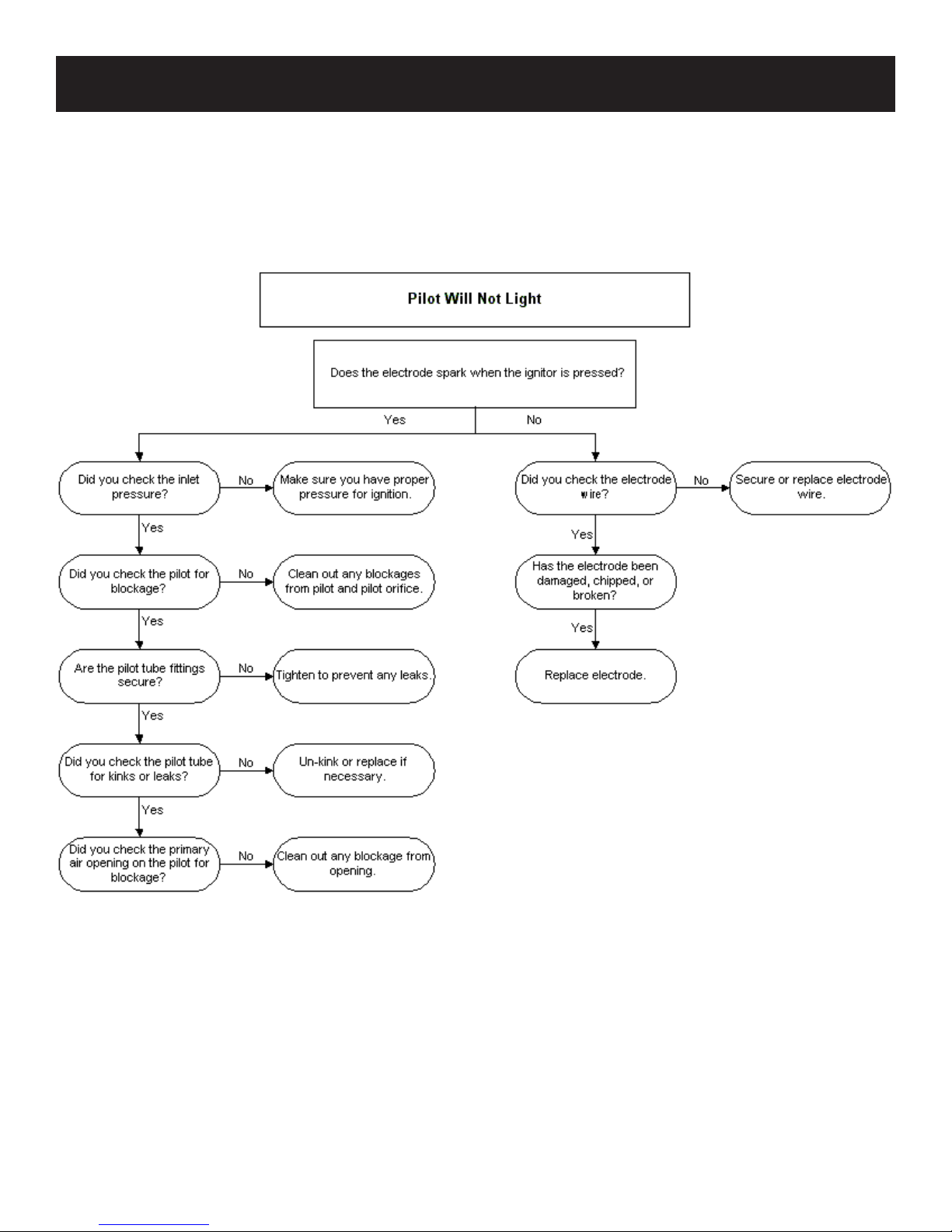
1. When ignitor button is pressed, there is no spark at ODS/
pilot.
a. Ignitor electrode positioned wrong - Replace pilot.
b. Ignitor electrode is broken - Replace pilot.
c. Ignitor electrode not connected to ignitor cable - Reconnect
ignitor cable.
d. Ignitor cable pinched or wet. Keep ignitor cable dry - Free
ignitor cable if pinched by any metal or tubing.
e. Broken ignitor cable - Replace ignitor cable.
f. Bad piezo ignitor - Replace piezo ignitor.
2. Appliance produces unwanted odors.
a. Appliance burning vapors from paint, hair spray, glues,
etc. - Ventilate room. Stop using odor causing products
while heater is running.
b. Gas leak - Locate and correct all leaks.
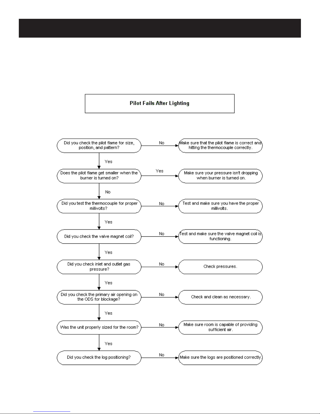
3. Appliance shuts off during use. (Pilot and main burner are
off.)
a. Not enough fresh air is available for ODS/pilot to operate
- Open window and/or door for ventilation.
b. Low line pressure - Contact local gas company.
c. ODS/pilot is partially clogged - Clean ODS/pilot.
d. Defective thermocouple - Replace pilot.
4. Appliance shuts off during use. (Pilot stays on.)
a. Low line pressure - Check line pressure to the valve.
b. Defective thermopile - Check pilot ame, check wire
connections, output should be a minimum of 325 millivolts
across. TH/TP and TP terminals with ON/OFF switch
off.
5. Gas odor even when control knob is in OFF position.
a. Gas leak - Locate and correct all leaks.
b. Control valve defective - Replace control valve.
6. When ignitor button is pressed, there is spark at ODS/pilot,
but no ignition.
a. Gas supply turned off or manual shutoff valve closed - Turn
on gas supply or open manual shutoff valve.
b. Control knob not in PILOT position - Turn control knob
to PILOT position.
c. Control knob not pressed in while in PILOT position - Press
in control knob while in PILOT position.
d. Air in gas lines when installed - Continue holding down
control knob. Repeat igniting operation until air is
removed.
e. ODS/pilot is clogged - Replace ODS/pilot assembly or get
it serviced.
g. Gas regulator setting is not correct - Replace gas
regulator.
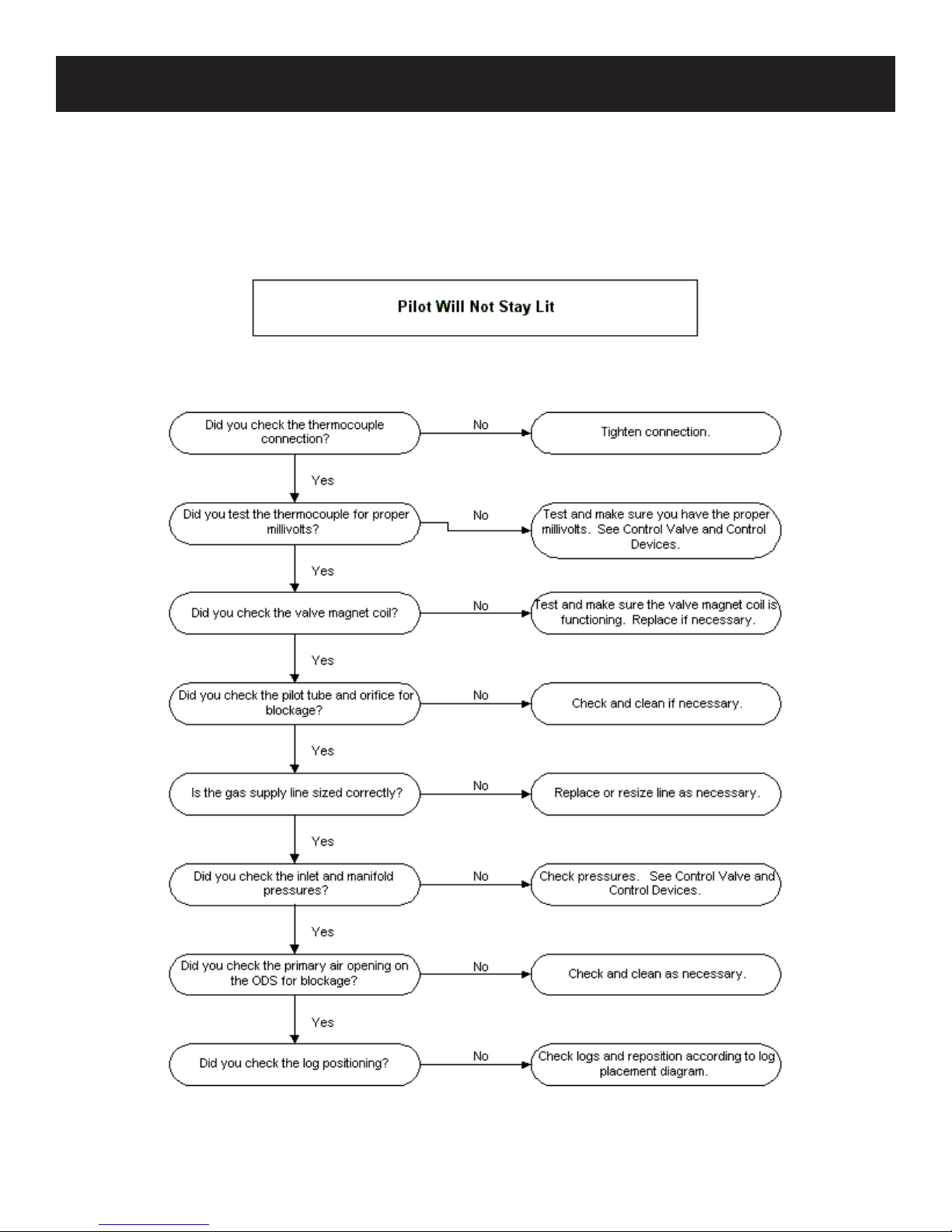
7. ODS/pilot lights but ame goes out when control knob is
released.
a. Control knob not fully pressed in - Press in control knob
fully.
b. Control knob not pressed in long enough - After ODS/pilot
lights, keep control knob pressed in 30 seconds.
c. Manual Shutoff valve not fully open - Fully open manual
shutoff valve.
d. Thermocouple connection loose at control valve - Hand
tighten until snug, then tighten 1/4 turn more.
e. Pilot ame not touching thermocouple, which allows
thermocouple to cool, causing pilot ame to go out. This
problem could be caused by either low gas pressure or
dirty or partially clogged ODS/pilot - Contact local gas
company.
f. Thermocouple damaged - Replace thermocouple.
h. Control valve damaged - Replace control valve.
8. Burner does not light after ODS/pilot is lit.
a. Burner orice clogged - Clean burner or replace main burner
orice.
b. Burner orice diameter is too small - Replace burner
orice.
c. Inlet gas pressure is too low - Contact qualied service
person.
9. If burning at main burner orice occurs (a loud, roaring
blow torch noise).
a. You must turn off burner assembly and contact a qualied
service person.
b. Manifold pressure is too low - Contact local gas
company.
c. Burner orice clogged - Clean burner or replace burner
orice.
10. Logs appear to smoke after initial operation.
a. Vapors from paint or curing process of logs - Problem will
stop after a few hours of operation. Run the heater with the
damper open if you have one, or open a window for the
rst few hours.
Log heater is intended to be smokeless. Turn OFF heater
and call qualied service person.
11. Heater produces a whistling noise when main burner is
lit.
a. Turning control knob to HIGH position when main burner
is cold - Turn control knob to LOW position and let warm
up for a minute.
b. Air in gas line - Operate burner until air is removed from
line. Have gas line checked by local gas company.
c. Dirty or partially clogged burner orice - Clean burner or
replace burner orice.
12. No gas to pilot.
a. LP-regulator shut down due to inlet pressure too high -
Verify LP tank regulator is installed and set at 11" to 13"
w.c. Replace regulator on heater.
13. New Installation.
a. On VFSV Model variable does not operate-On is OFF/OFF
is ON-wires into the back of receiver are reversed.
If the gas quality is bad, your pilot may not stay lit, the burners may produce soot and the heater may backre when lit. If the gas quality or
pressure is low, contact your local gas supplier immediately.
Sect1:13
Page 18
PROVISIONS FOR ADEQUATE COMBUSTION & VENTILATION AIR
This heater shall not be installed in a conned space unless provisions are
provided for adequate combustion and ventilation air.
The National Fuel Gas Code denes a conned space as a space whose
volume is less than 50 cubic feet per 1,000 Btu per hour (4.8m3 per kw) of
the aggregate input rating of all appliances installed in that space and an
unconned space as a space whose volume is not less than 50 cubic feet
per 1,000 Btu per hour (4.8 m3 per kw) of the aggregate input rating of all
appliances installed in that space. Rooms communicating directly with the
space in which the appliances are installed, through openings not furnished
with doors, are considered a part of the unconned space.
Unusually Tight Construction
The air that leaks around doors and windows may provide enough fresh
air for combustion and ventilation. However, in buildings of unusually
tight construction, you must provide additional fresh air.
Unusually tight construction is dened as construction where:
a. Walls and ceilings exposed to the outside atmosphere have a con-
tinuous water vapor retarder with a rating of one perm or less with
openings gasketed or sealed, and
b. Weatherstripping has been added on openable windows and doors,
and
c. Caulking or sealants are applied to areas such as joints around
window and door frames, between sole plates and oors, between
wall-ceiling joints, between wall panels, at penetrations for plumb-
ing, electrical, and gas lines, and at other openings.
If your home meets all of the three criteria above, you must provide
additional fresh air.
Warning: If the area in which the heater may be operated is smaller than
that dened as an unconned space or if the building is of unusually tight
construction, provide adequate combustion and ventilation air by one of
the methods described in the National Fuel Gas Code, ANSI Z223.1/NFPA
54, Air for Combustion and Ventilation, or applicable local codes.
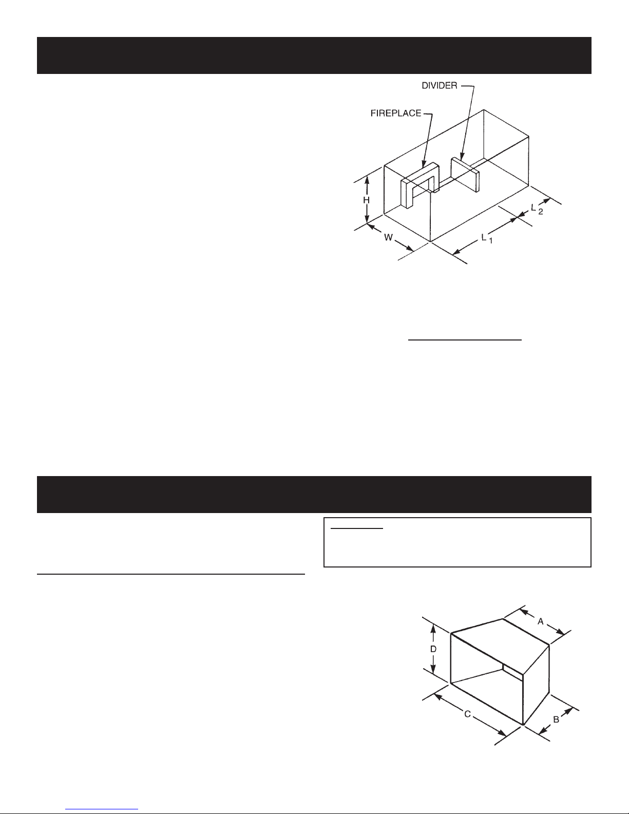
The following formula can be used to determine the maximum heater
rating per the denition of unconned space:
If the area in which the heater may be operated is smaller than that dened
as an unconned space, provide adequate combustion and ventilation air
by one of the methods described in the National Fuel Gas Code, ANSI
Z223.1, NFPA54.
Adhere to all codes, or in their absence, the latest edition of THE
NATIONAL FUEL GAS CODE ANSI Z223.1/NFPA54 which can be
obtained from:
American National Standards Institute National Fire Protection Association, Inc.
11 West 42nd St. Batterymarch Park
New York, NY 10018 Quincy, MA 02269
Example of Large Room with 1/2 Wall divider.
Figure 7
Btu/Hr =
(L1 + L2)FT x (W)FT x (H)FT
50
x 1000
CLEARANCES
Minimum Dimensions For Solid Fuel Burning Fireplaces
UL127 Factory Built Fireplaces (Figure 8)
Model A B C D
VFSV-16 18" 11 1/2" 24" 18"
VFSR-16 18" 11 1/2" 24" 18"
VFSV-18 17" 14" 28" 17"
VFSR-18 17" 14" 28" 17"
VFSM-18 21" 14" 32" 17"
VFSV-24 23" 14" 30" 18"
VFSR-24 23" 14" 30" 18"
VFSM-24 27" 14" 34" 18"
VFSV-30 26" 14" 34" 20"
VFSR-30 26" 14" 34" 20"
VFSM-30 30" 14" 38" 20"
The dimensions shown and dened in the replace manufacturer’s
instructions are minimum clearances to maintain in installing this
heater. Left and right clearances are determined when facing the
front of the heater.
Glass Doors
Make sure that glass doors are open during all operations of
the logset. The opening of the glass door frame should be the
dimension used for the minimum front opening of the rebox.
Follow these instructions to ensure safe installation.
Failure to follow instructions
exactly can create a
re hazard.
Figure 8
Sect1:14
Page 19
PILOT FLAME CHARACTERISTICS (continued)
Cleaning and Maintenance/Pilot
Oxygen Depletion Sensor Pilot (Figure 6)
When the pilot has a large yellow tip ame, clean the Oxygen
Depletion Sensor as follows:
1. Clean the ODS pilot by loosening nut B from the pilot tubing.
When this procedure is required, grasp nut A with an open end
wrench.
2. Blow air pressure through the holes indicated by the arrows.
This will blow out foreign materials such as dust, lint and spider
webs. Tighten nut B also by grasping nut A.
CLEANING AND SERVICING
Annual inspection and cleaning by your dealer or qualied
service technician is recommended to prevent malfunction
and/or sooting.
TURN OFF HEATER AND ALLOW TO COOL BEFORE
CLEANING.
Remove logs, handling carefully by holding gently at each end.
Gloves are recommended to prevent skin irritation from ceramic
bers. If skin becomes irritated, wash gently with soap and water.
Refer to manual for correct log placement.
PERIODIC CLEANING – Refer to parts diagram for location
of items discussed below.
• Do not use cleaning uid to clean logs or any part of heater.
• Logs - brush with soft bristle brush or vacuum with brush
attachment.
• Remove loose particles and dust from the burner areas,
controls, piezo covers and grate. Don’t remove crushed media
from inside burner box.
• Inspect and clean burner air intake holes. Remove lint or
particles with brush. Failure to keep air intake holes clean will
result in sooting and poor combustion.
Warning:
Never use needles, wires, or similar cylindrical objects to
clean the pilot to avoid damaging the calibrated ruby that
controls the gas ow.
Figure 6
ANNUAL CLEANING/INSPECTION – Refer to parts diagram
for location of items discussed below.
• Inspect and clean rear burner air intake holes. Remove lint or
particles with vacuum or brush. Failure to keep air intake
holes clean will result in sooting and poor combustion.
• Inspect and clean all burner ports.
• Inspect ODS pilot for operation and accumulation of lint at air
intake holes.
• Verify ame pattern and log placement for proper operation.
• Verify smooth and responsive ignition of main burner.
• Check level of glass media in burner. Burner should be full,
up to the level of openings in burner top.
Attention: Ceramic media that is dislodged from burner box
during shipment can be replaced through openings in burner
top. If settling of ceramic media occurs during shipment an
additional bag of ceramic media, part number, 12389 can be
ordered from Empire Comfort Systems, Inc.
Sect1:15
Page 20
PLACEMENT OF GLOWING EMBERS AND LAVA ROCK
Placement of the glowing embers (rock wool) is very individual
and light coverage will provide your best effects. We recommend
separation of the rock wool by hand and make your coverage as
light and uffy as possible.
Place just enough embers on the burner to obtain the glow and a
gold, yellow ame.
Do not place embers (rock wool) over large ports in rear portion
of burner.
Rock wool should not be placed in the area of the pilot assembly.
Replacement of loose material (glowing embers) must be purchased
from Empire Comfort Systems, Inc. Application of excess loose
material (glowing embers) may adversely affect performance of
the heater. WARNING: All previously applied loose material must
be removed prior to reapplication.
Refer to Parts List in owners manual to order loose material (rock
wool).
Placing Lava Rock in Front of Burner on Fireplace Floor
Spread lava rocks on replace oor in front of the burner pan.
The lava rocks are for decorative effect and are not required for
replace operation.
ATTENTION: DO NOT PLACE LAVA ROCKS ON BURNER, LOGS OR ROCK WOOL. THE LAVA ROCKS SHOULD
ONLY BE PLACED ON THE FIREPLACE FLOOR.
FIREPLACE PREPARATION
• Turn off gas supply to replace or rebox.
• Have the replace oor and chimney professionally cleaned to remove
ashes, soot, creosote or other obstructions.
Have this cleaning performed annually after installation.
• Seal any fresh air vents or ash clean-out doors located on oor or wall
of replace. If not, drafting may cause pilot
outage or sooting. Use a heat-resistant sealant. Do not seal chimney
ue damper.
Install and operate the appliance as directed in this manual.
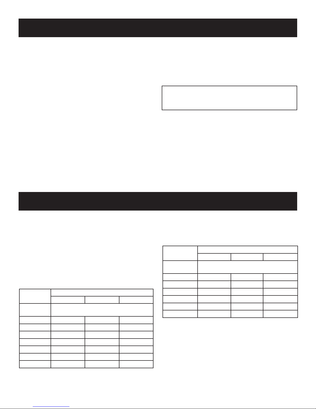
FOR FACTORY BUILT FIREPLACES
FREE OPENING AREA OF CHIMNEY DAMPER FOR VENTING
COMBUSTION PRODUCTS FROM DECORATIVE APPLIANCES
FOR INSTALLATION IN SOLID FUEL BURNING FIREPLACES
Appliance Input Rate (BTU/hr)
20 30 40
Chimney
Height* (ft)
10 11.3 16.6 22.1
15 8.6 12.6 17.3
20 7.5 10.8 14.5
25 6.6 9.6 12.6
30 6.2 9.1 11.3
35 5.7 8.0 10.8
40 5.3 7.5 10.2
* Height is from hearth to top of chimney and the minimum height
is 10 feet.
** Chart shows minimum opening (sq. in.) for given height and input
rate.
Minimum Opening** (sq. in.)
FOR MASONRY BUILT FIREPLACES
FREE OPENING AREA OF CHIMNEY DAMPER FOR VENTING
COMBUSTION PRODUCTS FROM DECORATIVE APPPLIANCES
FOR INSTALLATION IN SOLID FUEL BURNING FIREPLACES
Appliance Input Rate (BTU/hr)
20 30 40
Chimney
Height* (ft)
6 17.6 25.7 33.8
8 16.5 23.7 31.2
10 15.1 21.7 28.7
15 14.1 19.9 26.1
20 12.9 18.5 23.7
30 12.2 16.9 21.6
* Height is from hearth to top of chimney and the minimum height is
6 feet.
** Chart shows minimum opening (sq. in.) for given height and input
rate.
Minimum Opening** (sq. in.)
Sect1:16
Page 21

Sect1:17
Page 22

SERVICE NOTES
Sect1:18
Page 23

SERVICE NOTES
Sect1:19
Page 24

Sect1:20
Page 25

Direct Vent Fireplace
Troubleshooting
Sec2:1
Page 26
DIAGNOSING DIRECT VENT FIREPLACES
Sec2:2
Page 27
DIAGNOSING DIRECT VENT FIREPLACES
Sec2:3
Page 28
DIAGNOSING DIRECT VENT FIREPLACES
Sec2:4
Page 29
DIAGNOSING DIRECT VENT FIREPLACES
Sec2:5
Page 30
DIAGNOSING DIRECT VENT FIREPLACES
Sec2:6
Page 31

DIAGNOSING DIRECT VENT FIREPLACES
Sec2:7
Page 32

DIAGNOSING DIRECT VENT FIREPLACES
Sec2:8
Page 33

DIAGNOSING DIRECT VENT FIREPLACES
Sec2:9
Page 34

DIAGNOSING DIRECT VENT FIREPLACES
Sec2:10
Page 35

SOOTING CAUSES
Sec2:11
Page 36

VERTICAL DIMENSION FROM THE BOTTOM OF THE UNIT
TO THE CENTER OF THE FLUE OUTLET
WITH VERTICAL OR HORIZONTAL TERMINATION CAPS
VENTING FIREPLACE - TOP
To Use the Vent Graph (Figure 9)
1. Determine the height of the center of the horizontal vent
pipe. Using this dimension on the Sidewall Vent Graph,
locate the point it intersects with the slanted graph
line.
2. From the point of this intersection, draw a vertical line
to the bottom of the graph.
3. Select the indicated dimension, and position the unit in
accordance with same.
EXAMPLE A:
If the vertical dimension from the oor of the unit is 35
feet, the horizontal run to the outer wall ange must not
exceed 6.5 feet.
EXAMPLE B:
If the vertical dimension from the oor of the unit is 6.5
feet, the horizontal run to the outer wall ange must not
exceed 14.5 feet.
SPECIAL NOTE: For each 45 degree elbow installed in
the horizontal run, the length of the horizontal run MUST be
reduced by 18" (45cm). This does not apply if the 45 degree
elbows are installed on the vertical part of the vent system.
Reduce 3' for every 90° elbow.
Example: According to the chart the maximum horizontal
vent length is 20' and if two 45 degree elbows are required
in the horizontal vent it must be reduced to 17'.
The maximum number of 45 degree elbows permitted per
side wall installation is two (2). These elbows can be installed
in either the vertical or horizontal run.
Note: On vertical venting the rst elbow does not get
counted.
Venting Graph (Dimensions in Feet)
Figure 9
Acceptable vertical and horizontal vent run.
(40' maximum vertical and 20' maximum horizontal)
Unacceptable vertical and horizontal vent run.
Sec2:12
Page 37

24”
24” MINIMUM
CLEARANCE TO
COMBUSTIBLES
EXAMPLES - TOP VENT RUN
Figure 10
Figure 11
Sec2:13
Figure 12
Page 38

VERTICAL DIMENSION FROM THE BOTTOM OF THE UNIT
TO THE CENTER OF THE FLUE OUTLET
WITH VERTICAL OR HORIZONTAL TERMINATION CAPS
26
27
28
29
30
31
32
33
34
35
36
37
38
39
40
HORIZONTAL RUN
REAR EXIT-VERTICAL AND HORIZONTAL TERMINATION
(DIMENSIONS IN FEET)
REAR HORIZONTAL
VENT CONNECTION
B
A
DVD48FP(ONLY)
VENTING FIREPLACE - REAR
To Use the Vent Graph (Figure 13)
1. Determine the height of the center of the
horizontal vent pipe. Using this dimension on
the Sidewall Vent Graph, locate the point it
intersects with the slanted graph line.
2. From the point of this intersection, draw a vertical
line to the bottom of the graph.
3. Select the indicated dimension, and position the
unit in accordance with same.
EXAMPLE A:
If the vertical dimension from the oor of the unit
is 12 feet, 4 inches the horizontal run to the outer
wall ange must not exceed 12 feet, 3 inches.
EXAMPLE B:
If the vertical dimension from the oor of the unit
is 6 feet, 9 inches, the horizontal run to the outer
wall ange must not exceed 6 feet, 6 inches.
SPECIAL NOTE: For each 45 degree elbow
installed in the horizontal run, the length of the
horizontal run MUST be reduced by 18" (45cm).
This does not apply if the 45 degree elbows are
installed on the vertical part of the vent system.
Reduce 3' for every 90° elbow.
Example: According to the chart the maximum
horizontal vent length is 20' and if two 45 degree
elbows are required in the horizontal vent it must
be reduced to 17'.
The maximum number of 45 degree elbows
permitted per side wall installation is two (2).
These elbows can be installed in either the vertical
or horizontal run.
Venting Graph (Dimensions in Feet)
Note: When rear venting unit, adjust air shutter
from 1/16" open up to between 1/8" and 3/16"
for NAT gas.
Adjust air shutter from 1/4" open to between 5/16"
and to 3/8" for LP gas.
Figure 13
Acceptable vertical and horizontal vent run.
Unacceptable vertical and horizontal vent run.
Note: When rear venting unit, adjust air shutter from 1/16" open
up to between 1/8" and 3/16" for NAT gas.
Adjust air shutter from 1/4" open to between 5/16" and 3/8" for
LP gas.
Sec2:14
Page 39

EXAMPLES - REAR VENT RUN
Model Maximum Pipe
DVD32 24"
DVD36 24"
DVD42 24"
DVD48 6"
Figure 15
Length H1
Figure 14
Model Maximum Pipe
DVD32 24"
DVD36 24"
DVD42 18"
DVD48 N/A
Figure 16
Sec2:15
Length H1
Figure 17
Page 40

REAR VENT CONVERSION
Note: Discard insulation
& retainer when using
vertical venting off
VERTICAL VENTING
HORIZONTAL VENTING
FLUE INSULATION
INSULATION
RETAINER
INLET VENT COLLAR
INLET VENT COLLAR
FLUE OUTLET
COLLAR
FLUE COVER PLATE
(See note above)
INLET VENT
COVER PLATE
FLUE COVER PLATE
INLET VENT
COVER PLATE
Note:Itis recommended that the
flue cover plate tab be pulled
outward prior to removal.
This will ensure that the plate
is not accidentally dropped
inside the rear air chamber.
Note: Discard insulation
& retainer when venting off
top of fireplace.
Converting ue take-off to rear venting
When switching out the ue and inlet vent collars to run horizontally
off the rear vent, the following steps must be taken.
1. Remove the inlet vent collar (8 screws) and ue collar (4 screws)
from the top of the replace, and set to the side.
2. Remove the inlet cover plate and ue cover plate located on the
back of the replace. These will be used to close the top ue
and inlet openings.
3. Insert the insulation retainer bracket and insulation into the top
ue pipe before reinstalling the ue cover plate over the top ue
with 4 screws.
4. Reinstall the inlet cover plate over the top inlet opening with 4
5. Install the ue collar assembly to the rear ue with 4 screws.
6. Install the inlet vent collar to the rear of the replace with 8
7. This completes the conversion for a rear vent application.
screws. See illustration above..
screws.
Note: for top vented installations, the insulation and retainer are
to be removed from the ue pipe and discarded.
Sec2:16
Page 41

WALL THIMBLE
(MAXIMUM OF
THREE 90 ELBOWS)
(MAXIMUM OF
TWO 90 ELBOWS)
VENT SYSTEM IDENTIFICATION
Installing Vent Components (Figure 18)
Begin the vent system installation by installing the rst Simpson
Duravent component, 90° elbow to the starting collars or straight
pipe on the top of the appliance, then the straight pipe length and
then horizontal or vertical termination kit.
NOTE: All outer connection joints must be sealed with aluminum
tape, screws or silicone sealant rated above 300°F/149°C. The
inner ue joints do not require any sealant.
Simpson Duravent vent system components lock into place by
sliding the concentric pipe section with four (4) equally spaced
interior beads onto the appliance collar or previously installed
component end with four (4) equally spaced indented sections.
When the internal beads of each starting outer pipe line up, rotate
pipe section clockwise 90° (approximately 3 inches). The vent pipe
is now locked together.
Continue adding components per the pre-planned vent system
conguration. Be certain that each succeeding vent component
is securely tted and locked into the preceding component in the
vent system.
Figure 18
Special Venting Components (Simpson Duravent)
See Empire Comfort Systems Retail Price List for Simpson Duravent part
numbers and pricing.
Special DV Vent Kits
Available from Empire Comfort Systesm, Inc. dealers
DVVK-4FV Vertical Flex Vent Kit 4" x 7"
DVVK-4VP
(DVVK-4V)
DVVK-4TP
(DVVK-4T)
DVVK-4RP
(DVVK-4R)
Direct-Vent Fireplace Vent Kit - Vertical, Includes SD-991,
SD-953, and SD-943
Direct-Vent Fireplace Vent Kit for Top Vent, Thru-the-wall,
8 to 11 inch wall thickness, Includes SD-911, SD-985,
SD-990 and SD-942
Direct-Vent Fireplace Vent Kit for Rear Vent, 5 to 7 inch
wall thickness, (standard thru-the-wall venting) Includes
SD-908, SD-985 and SD-942
Direct-Vent Fireplace Vent Kit for Rear Vent, Thru-the
DVVK-4RE
wall, 5 to 7 inch wall thickness, (standard thru-the-wall
venting) Includes SD-908, SD985 and SD-942
DVVK-4TSP
(DVVK-4TS)
Direct-Vent Fireplace Vent Kit for Top Vent, Thru-the-wall,
5 to 7 inch wall thickness, Includes SD-908, SD-985,
SD-990 and SD-942
VIB6A Vertical Inlet Bafe Kit for 6 5/8" diameter.
VIB7A Vertical Inlet Bafe Kit for 7" diameter.
Sec2:17
Page 42

VENT CLEARANCES
Figure 19
A = *Clearance above grade, veranda, porch, deck or balcony
[*12 inches (30cm) minimum]
B = clearance to window or door that may be opened [*12 inches
(30cm) minimum for appliances < 100,000 Btuh (30kW)
C = clearance to permanently closed window [minimum 12
inches (30cm) recommended to prevent condensation on
window]
D = vertical clearance to ventilated soft located above the
terminal within a horizontal distance of 24 inches (60 cm) from
the center of the terminal [18 Inches (46 cm) minimum
E = clearance t o unventilated soffit [12 inche s 30cm)
minimum]
F = clearance to outside corner [See Page 2:19]
G = clearance to inside corner [See Page 2:19]
H = *not to be installed above a meter/regulator assembly
within 3 feet (90cm) horizontally from the center-line of
the regulator
I = clearance to service regulator vent outlet [*6 feet (1.8m)
minimum]
J = clearance to non-mechanical air supply inlet to building or
the combustion air inlet to any other appliance [*12 inches
(30cm) minimum for appliances ≤ 100,000 Btuh (30 kW)
36 inches (90cm) minimum for appliances > 100,000 Btuh
(30kW)]
K = clearance to a mechanical air supply inlet [* 6 feet (1.8m)
minimum]
L = †clearance above paved sidewalk or a paved driveway located
on public property [*7 feet (2.1m) minimum]
M = clearance under veranda, porch, deck, or balcony [*12 inches
(30cm) minimum ¥]
† a vent shall not terminate directly above a sidewalk or
paved driveway which is located between two single family
dwellings and serves both dwellings*
¥ only permitted if veranda, porch, deck, or balcony, is fully
open on a minimum of 2 sides beneath the oor*
* as specied in CGA B149 Installations Codes or ANSI
Z223.1. Note: Local Codes or Regulations may require
different clearances.
Sec2:18
Page 43

TERMINATION CLEARANCES
Termination clearance for buildings with combustible and noncombustible exteriors.
Vertical Sidewall Installations
Important! Minimum clearance between vent pipes and combustible materials is three (3") (76mm) on top, and (1") (25mm) on bottom
and sides.
Important! When vent termination exits through foundation less than 20" below siding outcrop, the vent pipe must extend outward so
that the horizontal vent terminal is located ush to, or beyond the outcrop siding.
Information on Various Venting Routes and Components
Important: It is always best to locate the replace in such a way that minimizes the number of offsets and horizontal vent length.
Since it is very important that the venting system maintain its balance between the combustion air intake and the ue gas exhaust, certain
limitations as to vent congurations apply and must be strictly adhered to.
The graph showing the relationship between vertical and horizontal side wall venting will help to determine the various vent lengths
allowable.
The horizontal vent run refers to the total length of vent pipe from the ue collar of the replace to the face of the outer wall.
The maximum horizontal vent run is 20 feet (457 cm) when the vertical vent rise is 8 feet (244 cm).
Venting terminals shall not be recessed into wall or siding.
Sec2:19
Figure 20
Page 44

VENT CAP
GAS VENT
H
LOWEST
DISCHARGE
OPENING
H (Min.)-Minimum height from
roof to lowest discharge opening
ROOF PITCH IS X/12
VERTICAL TERMINATION
ROOF PITCH H (Min.)
Flat to 6/12 12" (305 mm)
6/12 to 7/12 15" (381 mm)
Over 7/12 to 8/12 18" (457 mm)
Over 8/12 to 16/12 24" (610 mm)
Over 16/12 to 21/12 36" (914 mm)
Sec2:20
Page 45

DVVK-4FV DIRECT VENT TERMINATION KIT
Installation Instructions
This termination kit can only be used with Empire Comfort Systems direct vent replaces listed for use with
DVVK-4FV Vertical Flex Vent Kit. Please review the instructions packaged with your replace and verify the
replace model number. Check that this ex vent system is listed for use with your replace model prior to
starting the installation.
This vent kit may be installed as an OEM installation in a manufactured home (USA only) or mobile
home and must be installed in accordance with the manufacturer’s instructions and the manufactured
home construction and safety standard, Title 24 CFR, Part 3280 or Standard for Installation in Mobile
Homes, CAN/CSA Z240 MH.
CAUTION
All Fireplaces listed for use with the DVVK-4FV will operate safely when installed in accordance with this instruction manual. Read
all instructions before starting installation, then follow these instructions carefully to maximize replace performance and safety.
Report damaged parts to your dealer.
WARNING
Any common venting of the gas appliance using the DV vent kit with other gas appliances is not allowed. Do not connect this appli-
ance to a chimney ue servicing a separate solid fuel-burning appliance.
WARNING
Failure to follow these instructions may create a possible re hazard and will void the warranty.
WARNING
Always maintain minimum clearances around vent systems. The minimum clearance to combustibles for horizontal runs of vent pipe
is 3 inches from the top, and 1 inch from the sides and bottom of the vent system. Do not pack the open air spaces around the replace
or ue with insulation or other materials. Any horizontal run must have a 1/4” rise for every one (1) foot of run towards the vent ter-
mination. The vent above the roof must terminate vertically.
WARNING
Contact your Local Building and Fire Ofcials about restrictions and installation inspections in your area.
IMPORTANT SAFETY INFORMATION
• The vertical termination cap MUST be vented directly to the
outside. The termination kit MUST NEVER be connected to
a chimney ue(s) servicing a separate solid-fuel burning appliance or any other appliances.
• Termination cap MUST NOT be mounted horizontally.
• The exible vent pipe cannot be intermingled with any of the
rigid vent pipe section(s). DO NOT connect two sections of
exible vent pipe together to achieve a longer length without
the use of approved connectors.
• The installation must conform with local codes or in the ab-
sence of local codes, with the National Fuel Gas Code, ANSI
Z223.1 (in the United States) or with the current installation
code CAN/CGA B149 (in Canada).
• Only Direct Vent replaces approved for use with Empire
Comfort Systems, Inc. DVVK-4FV termination kit shall be
used. See PARTS LIST/ILLUSTRATIONS section for vent
component identication.
Sec2:21
• Horizontal vent runs must be supported every 2 feet using
wall straps. Vertical runs must be supported every 3 feet using wall straps. Slip wall straps loosely on to pipe. Attach
installer provided straps to framing members using nails or
screws.
• The replace and venting system should be inspected before
initial use and at least annually by a qualied eld service
person. Inspect the external vent cap on a regular basis to
make sure that no debris is interfering with the airow. Inspect entire venting system to ensure proper function.
• Please refer to the replace instructions for information on
Termination Cap clearances.
Page 46

PRE-INSTALLATION INFORMATION:
Items Required For Installation:
Tools Building Supplies
Phillips Screwdriver
Hammer
Saw and/or saber saw
Level
Measuring Tape
Electric Drill and Bits
Pliers
Square
Tin Snips
Before You Start:
Plan your installation. Read these instructions and the replace installation manual before installing unit and vent system. Set unit in
place and survey how best to vent the unit. After the vent conguration has been decided, stretch the ex pipe components out, then trim
off what will not be needed.
Refer to the replace installation manual for information on vertical venting requirements. The maximum length of vent when using ex
venting is 35 feet total. Contact your dealer or distributor for information on ex vent extension kits that may be added to the DVVK-4-
FV kit, in order to terminate up to 35 feet. Available extension kits include the DVEK-10 (10’ Flex) or the DVEK-25 (25’ Flex) extension
kits. The extension kits include connection hardware.
Installation of the Vertical Flex Termination Kit
Framing Materials
Wall Finishing Materials
Caulking Material (Noncombustible)
Support Strap supplies
WARNING
Ensure that the venting system exits the structure through the roof and does not terminate less than 12 inches (305mm) above the
roof.
WARNING
Refer to your replace homeowner’s manual for the minimum and maximum venting requirement of your replace prior to installation. Failure to do so may cause a re hazard.
WARNING
This exible pipe termination kit is ONLY for vertical terminations.
WARNING
Any horizontal run section must have a 1/4” rise for every one (1) foot of run towards the vent termination. Never allow the vent pipe
to run downward. This could cause high temperatures and may present a re hazard. This vertical kit may incorporate two (2) 90 de-
gree bends, but must terminate vertically.
CAUTION
This ex vent kit can be installed either vertically or horizontally off of Direct Vent Series replaces but must only terminate vertically.
WARNING
Because of sharp edges, always use gloves when handling the ex vent components.
CAUTION
Vent connections should overlap a minimum of 1” for proper sealing.
Always stretch and secure venting with metal strapping secured with nails (nails and strapping not supplied) to ensure that the ex
vent runs remain true.
If space permits, it is generally easier to attach venting in the top vent conguration.
CAUTION
INSTALLATION NOTE:
Sec2:22
Page 47

NAILS
(4) REQ'D.
THIMBLE
FIRESTOP
CEILING FRAMING
9½”Min.
(241mm)
9½” Min.
(241mm)
NOTE: ADDITIONAL
HOLES FOR ADJUSTING
THIMBLE UP OR DOWN
AS NEEDED
FLEX OUTER
AIR INTAKE PIPE
SPACER SPRINGS
FLEX FLUE PIPE
SPACER SPRINGS
4" FLEX
VENT PIPE
12”
305mm
12”
305mm
12”
305mm
12”
305mm
DVVK-4FV DIRECT VENT TERMINATION KIT (continued)
Step-By-Step Installation For Flex DV Kit
1. Unpack vent components and check all items for shipping
damage.
2. For this venting system to operate as designed it is dependent on the use of all parts and procedures detailed in these
instructions. Failure to follow these instructions may potentially affect the performance of this vent system and the attached appliance.
3. As per the replace manufacturer’s instructions, replace the
existing 6 5/8” diameter replace vent adapter with the 7”
diameter ex vent replace adapter included in the vent kit.
Install the adapter collar with the screws removed from the
standard replace collar. Refer to the replace manual for additional information on the vent collar removal and installation.
4. Once the replace location has been determined, mark the
ceiling where the ex vent will pass through. Cut an opening
for installation of the restop thimble assembly. The opening must measure a minimum of 9-1/2” x 9-1/2” square. See
Figure 21.
5. Next, determine the location for the cutout in the roof opening. This opening must be large enough to provide a mini-
mum 1” air space clearance from the vertical vent pipe to any
combustible framing.
6. Install the Firestop/Thimble assembly to the framed opening
in the ceiling using common nails or screws.
Note: The thimble assembly is adjustable up or down as
needed within the restop. It is also designed with a pivoting
restop for use with 0 - 3/12 pitch cathedral ceilings.
7. To begin vent system assembly, rst layout all the vent components on the oor in the order in which they will be as-
sembled.
8. Stretch the 4” diameter inner ex ue and 7” diameter outer
ex vent to the maximum length of 6 feet.
9. Install the spring spacers provided around the 4” diameter
ex ue at 1 foot intervals, then slide the ue pipe with spacers into the 7” diameter outer ex vent pipe. Make sure the
springs are spaced evenly starting at 12 inches from the re-
place collar. See Figure 22.
Sec2:23
Figure 21
Figure 22
Page 48

10. With the ex vent assembly and the 48” long hard pipe
WING NUT (2)
PIPE CLAMP
ROOF BRACKET (2)
NUT (2)
SCREW (2)
H
X
12
ROOF PITCH IS X/12
H (Min.)-Minimum height from
roof to lowest discharge opening
DISCHARGE
LOWEST
OPENING
VENT CAP
GAS VENT
components laid out on the oor, begin securing these parts
together. First, apply a generous bead of silicone sealant to
the inside of the 4” diameter ex ue (not the end with the
pre-installaed connector), then slide the ex ue over the 4”
diameter hard pipe ue. Be sure to overlap at least 1-1/4”. Secure this connection with a 4” diameter band clamp provided.
Be careful not to damage or tear the ex ue when tightening
clamp.
11. Repeat the connection process for the outer 7” diameter ex
vent to hard pipe connection. Use silicone sealant at this joint
also, overlap at least 1-1/4”, then secure the joint with the 7”
diameter band clamp provided. Be careful not to damage or
tear the ex vent pipe when tightening the clamp.
12. While the venting is still on the oor, assemble the roof jack
components as shown in Figure 23 and pre-install the roof
jack assembly to the hard pipe approximately 18” from the
top end of the hard pipe.
13. Now the pre-assembled vent system may be carried to the
roof, then lowered through the roof cutout opening (see step
5). Feed the ex vent end down through the roof opening and
restop/thimble assembly installed in steps 4 through 6.
14. Secure the roof support assembly to the roof sheathing with
at least (4) nails/screws through each support bracket. Check
that the combustible clearances through the roof framing will
maintain at least a 1” clearance from the vent pipe.
15. Determine how high the vent terminal should be located
above the roof line based on the roof pitch information shown
in Figure 24. Adjust the vent system height by loosening the
pre-installed roof support pipe clamp and sliding the vent
pipe up or down as pre-determined, then re-tighten the pipe
clamp. Install a couple of sheet metal screws through the pipe
clamp into the outer hard vent pipe to lock in place.
16. Check to make sure that the bottom end of the ex vent is
long enough to reach the replace adapter collars. If too long,
trim off the extra ex vent not needed.
Figure 23
ROOF PITCH H (Min.)
Flat to 6/12 12” (305mm)
6/12 to 7/12 15” (381mm)
Over 7/12 to 8/12 18” (457mm)
Over 8/12 to 16/12 24” (610mm)
Over 16/12 to 21/12 36” (914mm)
Figure 24
Sec2:24
Page 49

BANDCLAMP
APPLY HIGH
TEMPERAT URE
SEALANT
(WITH GASKET)
ADAPTER COLLAR
7" DIA. INLET
4" DIA. FLUE
ADAPTER
COLLAR
FLUE PIPE
4" DIA. FLEX
7” DIA. FLEX AIR
INTAKE PIPE
Vent Cap
Storm
Minimum
Clearance to
Combustibles
Collar
Exterior
Roof
Roof
Flashing
Support
Roof
Assembly
7"(178mm) Dia.
Must Extend
7"(178mm) Dia.
Hard Pipe
Through Roof
Flashing
1” (25mm)
Flex
DVVK-4FV DIRECT VENT TERMINATION KIT (continued)
17. To attach the vent connections at the replace, be sure the 7”
diameter adapter collar has been installed per step 3. Apply
a bead of silicone sealant to the 4” diameter ex connector,
then slide the ex pipe adapter collar into the replace ue
collar and secure by installing a minimum of two (2) screws
through the ue collar and into the adapter. See Figure 25.
18. Apply sealant to the 7” diameter adapter collar, slide outer
ex vent over the collar, then secure with a 7” diameter band
clamp. See Figure 25.
19. Once the lower connections are made and the ex pipe is
secured with support bands as required (3 feet minimum be-
tween supports) then the roof ashing can be installed. See
Figure 26.
20. Install the roof ashing, and seal using common constructions practices.
21. An additional storm collar band is provided in kit that may be
used as an attic insulation shield. The collar can be installed
around the ex pipe (or hard pipe) just above the restop
thimble. This collar will act as a shield to prevent blown insulation from entering the thimble.
22. To complete the vent installation, install the vent termination
cap to the top of the hard vent pipe assembly. Mate up the ue
and outer telescopes with the hard pipe assembly, then secure
by installing a minimum of two (2) sheet metal screws into
the overlapped anges of the cap and pipe.
23. Figure 27 shows a completed installation with components
identied and other installation information such as heights
and clearance to combustibles.
LP and Nat models
Figure 25
Sec2:25
Figure 26
Page 50

Storm
Clearance to
Combustibles
Collar
Exterior
Roof
Roof
Flashing
Roof Jack
Adjustable
Assembly
4' Long Rigid Pipe
Direct Vent
Fireplace
Required From
Vent Pipe
Firestop/Thimble
Ceiling
Straps (As Req'd.)
Venting Support
With Gasket&Clamps
7" Dia. Adapter Collar
4" Dia. Flue Connector
Assembly
Firestop/Thimble
Adjustable
Storm Collar (Use TO
Keep Insulation Out Of
Inlet Vent Connections
Clamps At Flue &
Vertical Termination
Thimble Assembly)
35 ft. Max
Note: DVVK-4VF Kit
Maximum Height
(including fireplace) Is
13’. To Extend Vent
Run, an Additional
Vent ExtensionKit
Is Necessary
Figure 27
Sec2:26
Page 51

DVVK-4FV DIRECT VENT TERMINATION KIT (continued)
Vertical Flex Termination Kit
Sec2:27
Item
Number Item Description Repair Part No.
1 4”/7” Vertical Termination Cap MF100038 1
2 Roof Support Kit MF100503 1
3 2 Ply Alum Flex 4” Diameter by 6 ft. MF04ALA2F006 1
4 2 Ply Alum Flex 7” Diameter by 6 ft. MF07ALA2F006 1
5 4”/7” x 48” Rigid Pipe Assembly MF100554 1
6 Firestop Thimble Assembly MF100124 1
7 Roof Flashing (0/12 to 6/12) MF100091 1
8 7” Flex Adapter Collar with Gasket MF100524 1
9 7” Storm Collar MF100147 2
10 Spring Spacers MF100548 5
N/S Clamp 4” Diameter MF100330 2
N/S Clamp 7” Diameter MF100534 2
N/S #8 x 1/2” Self Drilling Screws N/A 20
N/S HT Silicone N/A 1
N/S #8 x 5/8” Self Drilling Screws N/A 10
Quantity
Supplied
Page 52

X
X=13/3/4” MAX
TOTALWALL THICKNESS
(SUBTRACT 3” IF USING THE
DV822 VINYL SIDING KIT)
½” AIR
SPACE
CLEARANCE
11”
9”
NOTE: SPACING FLANGE
INSTALLED TO TOPSIDE
INTERIOR WALL
EXTENSION
THIMBLE
DVVK-4RE VENT KIT INSTALLATION INSTRUCTIONS
CAUTI O N : S h a r p e d g e s , use protective gl o v e s w h e n
installing.
Tools Needed for Installation:
Sheet metal snips
5/16” nut driver
Phillips head screwdriver - #2
High temperature sealant or furnace cement rated for continuous use
at 1,000oF minimum
Measuring tape
Parts Verication
See parts list on page 2:27 to verify components included in this vent
kit prior to installation.
NOTE: If installing onto wood, lap, or vinyl siding, the vinyl siding
kit should be used (sold separately, part number DV-822).
The vinyl siding vent kit, DV-822, is available from Empire Comfort
Systems, Inc. The depth is 3” (76mm), which enables the vent cap to
be extended away from vinyl siding or projections. The wall depth plus
the additional 3” (76mm) depth of the vinyl siding vent cap extension
should not exceed a total depth of 13 3/4” (349mm).
If wall depth exceeds 13 3/4” (349mm), extend system using
6 5/8” (168mm) x 4” (102mm) rigid venting (See Fireplace Instructions
for approved lengths) See Figure 29.
Installing Wall Thimble/Firestop Assembly
1. Fix replace to permanent location. If using rigid venting system,
install up to the location where it will exit the building.
2. Cut hole in wall for wall thimble/restop assembly (Figure 28)
into your combustible wall. Note: On brick or block exterior wall
a 7” (178mm) diameter hole needs to be cut.
Measure the total wall thickness to determine whether or not the
extension thimble is to be used. If the combustible wall depth is
over 5 3/8” (137mm), then the extension thimble should be used
(Figure 1).
3. Install the wall thimble assembly through the framed opening so
the restop plate is on the interior wall (Figure 28). Telescope
section should extend all the way through the exterior wall. Attach
with (4) 10 x 1” screws.
4. When placing the vent cap on an exterior wall covered with combustibles such as wood, lap, or vinyl siding, install the vinyl siding
kit to the exterior wall sheathing.
Figure 28
Nat models only
Figure 29
Cutting Vent Tubes
This is the most important part of the installation. With the
replace (and the rigid venting system if used) xed to its permanent location, the 6 5/8” (168mm) diameter air inlet tube and the
4” (102mm) diameter ue outlet tube are to be marked and cut
using the following procedure.
5. Attach the inlet tube to the outside mounting plate. Align
tinnerman clips on the tabs of the air inlet tube to the holes on
outside mounting plate, and x with (2) #10 x 1/2” screws.
6. With the vinyl siding kit installed to wall (if necessary), insert the 6
5/8” (168mm) diameter tube with outside mounting plate attached
through hole in wall. Connect to collar on replace or rigid vent
system. Measure between wall or vent cap extension and outside
mounting plate (Figures 30 and 31).
Sec2:28
Page 53

OUTSIDE WALL
MEASURE
VINYL SIDING KIT DV822
OUTSIDE MOUNTING
PLATE
EXT.WALL
SURFACE OR
VINYL SIDING KIT
FLUE
PIPE
CUT
2½”
BEYOND EXTERNAL
WALL SURFACE OR
VINYL SIDING KIT
1
”
VENT CAP END
APPLY SEALANT
ON THE INSIDE
DO NOT PLACE
OVERLAPPED
SECTION OVER
THE SEAM IN THE TUBE
DVVK-4RE VENT KIT INSTALLATION INSTRUCTIONS (continued)
the opposite end. Do not crimp or enlarge tube.
8. Attach the 4” (102mm) diameter ue outlet tube onto the rigid
venting system or directly to replace. Ensure the 4” (102mm)
diameter ue outlet tube is placed as far as possible onto the rigid
venting system. Mark the 4” (102mm) diameter ue outlet tube
2 1/2” (64mm) beyond the vinyl siding kit or wall. See Figure
31. Remove the 4” (102mm) diameter ue outlet tube from rigid
venting system. When installing directly to replace, tape gasket
needs to be used.
9. Mark or wrap tape completely around the tubes at the marked points
to help in making a true cut. Do not crimp or enlarge tubes.
10. From outside: Push the 6 5/8” (168mm) diameter inlet tube/mounting plate onto end of rigid venting system to correct position. Fasten
the outside mounting plate to the vinyl siding kit or wall with (4)
10 x 1 1/2” screws. (Ensure upward slope).
Figure 30
7. Remove outside mounting plate with tube attached from wall. Mark
and cut the extra length of the 6 5/8” (168mm) diameter tube from
11. From inside: Attach the inlet tube to the collar on the back of
the replace (or the rigid venting system) using (3) self tapping
screws.
12. Seal the 4” (102mm) diameter ue outlet tube. Follow instructions
and diagram (Figure 32).
13. Fasten 4” (102mm) diameter ue outlet tube in place. Do not “twist”
the ue outlet tube into the replace collar (or rigid venting sys-
tem). Hold the tube by the seam and push in using a perpendicular
“rocking” motion. This ensures the seam on the tube stay intact.
Figure 31
Sec2:29
14. Fasten vent cap end using (3) 10 x 1/2” screws to mounting plate.
Sealing 4” (102mm) Diameter Flue Outlet Tube
Figure 32
Note: Tape gasket to be applied prior to installing to replace ue outlet tube
only. Tape gasket should not be used when mating the ue outlet tube to a rigid
venting system.
Page 54

DVVK-4RE VENT KIT INSTALLATION INSTRUCTIONS (continued)
Follow correct option according to venting method.
Connecting Directly to Fireplace
If the air inlet and ue outlet tubes are to be connected directly to
the unit (no rigid venting system is being used), then the gasket
provided must be used to seal the 4” (102mm) ue outlet tube.
Peel the paper off the self-adhesive gasket and then wrap it around
the end of the tube (if tube was cut, it is recommended to use cut
end) as shown in Figure 56. Pull the gasket tight at all times while
wrapping it around tube. The gasket ends should align, to form a
complete seal. The overlapped section should NOT come in contact with the seam in the tube. Apply high temperature sealant to
the opposite end of the tube (on the inside of the tube). The end
with the gasket will attach to the back of the unit. Continue with
Step 13.
PARTS LIST
INDEX
NUMBER
1 DV769 Vent Cap Assembly
2 19193 Outside Mounting Plate
3 19194 Air Inlet Tube
4 DV524 Flue Outlet Tube
5 19196 Firestop/Thimble Assembly
6 20527 Gasket
PART
NUMBER
DESCRIPTION
Connecting to Rigid Vent System
If the air inlet and ue outlet tubes are to be connected to a rigid
venting system (and not directly to the back of the unit), then do
not use the gasket provided. High temperature sealant should be
applied to the outside of the 4” diameter (102mm) ue outlet tube
(if tube was cut, it is recommended to use cut end) and to the inside of the tube on the end that connects to the vent cap. Continue
with step 13.
Sec2:30
Page 55

8
(203 mm)
8
(203 mm)
8
(203 mm)
4 FLEX
VENT PIPE
SPACER
SPRING
FIGURE B
””
”
”
”
FLEX OUTER VENT FLEX FLUE PIPE
SPACER
SPRINGS
FIGURE A
To pofVent
Combustibles NOT
allowed in shaded
area
1"
1"
3"
(25 mm)
7
” Diameter
intake vent
4” Diameter flue
(25 mm)
(76 mm)
FIGURE D
BAND CLAMP
4 DIA. FLUE
ADAPTOR
COLLAR
4 DIA. FLEX
FLUE PIPE
7 DIA. FLEX
VENT PIPE
APPLY HIGH
TEMPERATURE
SEALANT
7 DIA. INLET
ADAPTOR COLLAR
(WITH GASKET)
FIGURE C
”
”
”
”
DVVK-4F FLEX VENT INSTRUCTIONS
The DVVK-4F FLEX VENT KIT includes the following components:
• (1) Horizontal Termination Cap
• (1) 4-foot section of Flex vent with spacers (4" ue/7" outer
pipe)
• (1) 4" dia. Flue adapter collar
Flex venting can be installed either vertically or horizontally off of the DVP36 Series replaces. When installing a horizontal vent run from
top connections, maintain at least ½" rise for every 12" of vent run. When venting horizontal off the rear vent connections, allow a minimum
rise of 2". Refer to Figure 30 when mounting termination near vinyl siding.
CAUTION: Always stretch and secure venting with wire or metal strapping to ensure that the horizontal runs do not sag.
If space permits, it is generally easier to attach venting in the top vent conguration.
Because of sharp edges, always use gloves when handling the ex vent components.
Vent connections should overlap a minimum of 1" for proper sealing.
Always follow the general venting requirements for vent terminal location, vent lengths, and clearance to combustible materials.
INSTALLATION
1. Unpack vent components and check that all items are included.
2. Check to see that the vent spacer springs are located around the ue
vent at 8" and 12" intervals along its length. See Figure A. If not,
stretch the spacer springs to about 15" long and wrap them around
the ue, then interlock the ends of each spring about 2". See Figure
B. Maintain equal distance between spring spacers.
• (1) 7" dia. Outer Vent adapter collar
• (1) Wall Firestop/Thimble Assembly
• Hardware pack that includes band clamps and screws
7. If the venting is to long, trim off any excess vent before attaching
the vent end connectors.
8. Attach the Termination Cap to the outside of the house.
9. Prior to making the vent connections, apply high temperature
sealant (1000 degree F min.) to the vent connections before securing
with the band clamps provided. Note: the flue pipe end without the
adapter is to be installed to the Termination Cap.
10. Apply sealant to the outside of the flue pipe adapter and connect
to the flex flue pipe. Then insert the adapter into the fireplace flue.
Secure flue adapter to the fireplace flue with a minimum of two
screws provided. See Figure C.
11. Attach the Outer Vent pipe to the 7" dia. Collar on the fireplace with
a large band clamp provided. Sealant may also be used on the outer
vent connections.
12. Check all vent connections for tightness. Make sure horizontal
venting has the proper rise and combustible clearances required.
Refer to venting charts in fireplace instruction manual.
3.
Remove the 6-⅝" dia. Vent collar from the fireplace. Replace this
4. Slide the Flex Vent flue pipe into the Outer Flex Vent pipe.
5. Install the Wall Firestop/Thimble assembly as required through the
6. In most cases, after determining the length of the vent that is
collar with the 7" dia. Flex Vent adapter collar provided with the
vent kit.
wall. Refer to the venting charts in the fireplace manual to determine
the proper height and size of the vent opening. The minimum
opening should be 9" wide by 11" high. The minimum combustible
clearance from the horizontal vent is 1" from sides and bottom, and
3" above the vent pipe. See Figure D.
needed, it may be easier to install the flue and outer vent pipes to
the Termination Cap first, then from the outside, feed the venting
through the wall to the fireplace.
Sec2:31
Page 56

SERVICE NOTES
Sec2:32
Page 57

SERVICE NOTES
Sec2:33
Page 58

Sec2:34
Page 59

B Vent Fireplace Troubleshooting
Sec3:1
Page 60

DIAGNOSING B VENT FIREPLACES
Sec3:2
Page 61

DIAGNOSING B VENT FIREPLACES
Sec3:3
Page 62

DIAGNOSING B VENT FIREPLACES
Sec3:4
Page 63

DIAGNOSING B VENT FIREPLACES
Sec3:5
Page 64

DIAGNOSING B VENT FIREPLACES
Sec3:6
Page 65

DIAGNOSING B VENT FIREPLACES
Sec3:7
Page 66

DIAGNOSING B VENT FIREPLACES
Sec3:8
Page 67

DIAGNOSING B VENT FIREPLACES
Sec3:9
Page 68

DIAGNOSING B VENT FIREPLACES
Sec3:10
Page 69

SOOTING CAUSES
Sec3:11
Page 70

SERVICE NOTES
Sec3:12
Page 71

SERVICE NOTES
Sec3:13
Page 72

Sec3:14
Page 73

Control Valve and Control Devices
Sec4:1
Page 74

Gas Inlet
Air Mixer
Thermocouple
Thermopile
Pilot Barrel
LP ODS PILOT
Ceramic Ignitor
Thermopile Output = 750 MV Max
Thermocouple Output = 30 MV Max
Sec4:2
Page 75

Gas Inlet
Air Mix
Thermopile
NATURAL ODS PILOT
Sec4:3
Pilot Barrel
Thermocouple
Ceramic Ignitor
Thermopile Output = 750 MV Max
Thermocouple Output = 30 MV Max
Page 76

Hot Junction
450° temperature
difference between Hot
and Cold Junction
Cold Junction
Mounting Nut
Thermopile Lead
750 MV Maximum
Negative Terminal
(White)
Positive Terminal
(Red)
Sec4:4
Page 77

THERMOCOUPLE
ELECTRODE
PILOT
THERMOPILE
GAS CONTROL KNOB SHOWN
IN "OFF" POSITION
REMOTE
OFF
ON
STANDING PILOT LIGHTING INSTRUCTIONS
FOR YOUR SAFETY, READ BEFORE LIGHTING
WARNING: If you do not follow these instructions exactly, a re or explosion may result
causing property damage, personal injury or loss of life.
A. This appliance has a pilot which must be lighted by hand.
When lighting the pilot, follow these instructions exactly.
B. Before lighting smell all around the appliance area for gas.
Be sure to smell next to the oor because some gas is heavier
than air and will settle on the oor.
What To Do If You Smell Gas
• Do not try to light any appliance.
• Do not touch any electrical switch;
• Do not use any phone in your building.
• Immediately call your gas supplier from a neighbor's
phone. Follow the gas supplier's instructions.
LIGHTING INSTRUCTIONS
1. Stop! Read the safety information above.
2. Set REMOTE/OFF/ON switch to OFF.
3. Turn off all electric power to the appliance (if applicable).
4. Lower bottom louver assembly.
5. Push in gas control knob slightly and turn clockwise
to "OFF."
Note: Knob cannot be turned from "PILOT" to "OFF" unless
knob is pushed in slightly. Do not force.
6. Wait ten (10) minutes to clear out any gas. Then smell for gas,
including near the oor. If you then smell gas, STOP! Follow
"B" in the safety information above. If you do not smell gas,
go to the next step.
7. Find pilot - Follow metal tube from gas
control. The pilot is behind the burner
on the right side.
8. Turn gas control knob counterclockwise
to "PILOT."
• If you cannot reach your gas supplier, call the re
department.
C. Use only your hand to push in or turn the gas control knob.
Never use tools. If the knob will not push in or turn by hand,
don't try to repair it; call a qualied service technician. Force
or attempted repair may result in a re or explosion.
D. Do not use this appliance if any part has been under water.
Immediately call a qualied service technician to inspect the
appliance and to replace any part of the control system and
any gas control which has been under water.
9. Push in control knob all the way and hold in. Repeatedly push
the piezo ignitor button until the pilot is lit. Continue to hold
the control knob in the for about one (1) minute after the pilot is
lit. Release knob, and it will pop back up. Pilot should remain
lit. If it goes out, repeat steps 5 through 9.
• If the control knob does not pop up when released, STOP
and IMMEDIATELY call a qualied service technician
or gas supplier.
• If the pilot will not stay lit after several tries, turn the gas
control knob to "OFF" and call your service technician
or gas supplier.
10. Turn gas control knob counterclockwise to "ON."
11. Close bottom louver assembly.
12. Turn on all electric power to the appliance (if applicable).
13. Set REMOTE/OFF/ON switch to desired setting.
TO TURN OFF GAS TO FIREPLACE
1. Set REMOTE/OFF/ON switch to OFF.
2. Turn off all electric power to the appliance if service is to
Sec4:5
be performed (if applicable).
3. Lower bottom louver assembly.
4. Push in gas control knob slightly and turn clockwise
to "OFF." Do not force.
5. Close bottom louver assembly.
Page 78

RobertShaw Valve
ElectroHeat
Dexen
Sec4:6
Page 79

TH/TP-TP = Thermopile
TH-TH/TP = Control
TH
TP
TH/TP
Manifold Pressure Tap
Regulator Vent
Gas Cock
R5700 - NAT
R5701 - LP
Gas Inlet
Pilot Supply
Outlet
Pilot Circuit Wire (EPU)
Pilot Adjustment Screw
(Behind Cover Screw)
Manifold Regulator
Adjustment Cap & Screw
Sec4:7
Page 80

Manifold Pressure Tap
Regulator Vent
TH
TP
TH/TP
TH/TP-TP = Thermopile
TH-TH/TP = Control
R5700 - NAT
R5701 - LP
Gas Cock
Gas Inlet
Pilot Supply
Outlet
Inlet Pressure Tap
Pilot Adjustment
Screw
Pilot Circuit Wire (EPU)
Manifold Regulator
Adjustment Cap & Screw
Sec4:8
Page 81

Robertshaw Valve Check
FROM TO DESIRED READING CHECK FOR
TH/TP TP
Pilot Only Burning
TH/TP TP
Unit Calling for Heat
TP TH/TP 9 to 11 OHMS Pilot magnetic safety coil
TP TH 1.3 to 1.7 OHMS Burner head magnetic coil
TP End of Black Wire 9 to 11 OHMS Feed to back of valve
Disconnect all wires before making checks.
450 - 550 MV Proper MV output for
thermopile
40% - 60% Drop Proper Gas Valve Operation
NATURAL PROPANE
Gas Inlet Pressure Minimum
Maximum
Manifold Pressure 3.5” - 4.0” W.C. 10.0” W.C.
5.0” W.C.
10.5” W.C.
Check Rating Plate
11.0” W.C.
13.0” W.C.
Sec4:9
Page 82

Gas Inlet
Inlet Pressure Tap
Manifold Pressure Tap
Gas Cock
TH/TP-TP = Thermopile
TH-TH/TP = Control
High \ Lo Adjustment Knob
TH/TP
TP
R7577 - NAT
R7578 - LP
TH
Gas Outlet
Pilot Adjustment
Screw
Pilot Supply
Outlet
Sec4:10
Page 83

SIT Valve Check
FROM TO DESIRED READING CHECK FOR
TH/TP TP
Pilot Only Burning
TH/TP TP
Unit Calling for Heat
TP TH/TP 9 to 11 OHMS Pilot magnetic safety coil
TP TH 1.3 to 1.7 OHMS Burner head magnetic coil
TP End of Black Wire 9 to 11 OHMS Feed to back of valve
Disconnect all wires before making checks.
450 - 550 MV Proper MV output for
thermopile
40% - 60% Drop Proper Gas Valve Operation
NATURAL PROPANE
Gas Inlet Pressure Minimum
Maximum
Manifold Pressure 3.5” - 4.0” W.C. 10.0” W.C.
5.0” W.C.
10.5” W.C.
Check Rating Plate
11.0” W.C.
13.0” W.C.
Sec4:11
Page 84

Thermocouple
Inlet
Gas Inlet
TH
TH/TP
TH/TP-TP = Thermopile
TH-TH/TP = Control
TP
Inlet Pressure Tap
R4323 - NAT
R4324 - LP
Manifold Pressure Tap
Hi-Lo Adjustment
Piezo Ignitor
Piezo Ignitor
Wire
Gas Cock
Sec4:12
Page 85

PROCEDURE
knob turned to OFF. If coil resistance exceeds
3.6 ohms, replace the valve.
SHOULD BE:
METER READING
lit with Pilotstat knob turned to PILOT. If the
reading is less than 460 mV, make sure pilot
ame is getting thermopile hot or replace the
thermopile.
Pilotstat knob turned to PILOT. Reading should
be a minimum of 12 mV in a new ODS pilot
burner assembly. If the reading is less than 12
mV, replace the ODS pilot burner assembly. The
power unit will hold in down to 3 mV. If the
output of the thermocouple is less than 3 mV,
replace the ODS pilot burner assembly.
with Pilotstat knob turned to PILOT. Close the
thermostat contacts. Operator will pull in with
a minimum of 155 mV. Operator makes audible
sound during pull-in. If pull-in does not occur,
replace the valve.
thermostat and lead wires should not exceed 1.7
ohms. If reisistance is above 1.7 ohms, reduce
the resistance.
SET
THERMOSTAT
BETWEEN
MULTIMETER
TERMINALS
Honeywell Vent-Free Millivolt Gas Valve Check
TEST TITLE CONNECT
Sec4:13
Coil Resistance TP and TH Open Maximum of 3.6 ohms Have thermostat contacts open and Pilotstat
Thermopile TP and TPTH Open Minimum of 460 mV. Have thermostat contacts open and the pilot
Thermocouple Tip (and Ground) Open Minimum of 12 mV. Have thermostat contacts open and pilot lit with
Operator Pull-In TH and TP Open Minimum of 155 mV. Have thermostat contacts open and pilot lit
Resistance System -- Closed Maximum of 1.7 ohms System resistance from the remote switch or
Page 86

11.0” W.C.
NATURAL PROPANE
5.0” W.C.
13.0” W.C.
10.0” W.C.
4.9” W.C.
10.0” W.C.
3.5” W.C.
1.7” W.C.
Low
Maximum
Gas Inlet Pressure Minimum
Manifold Pressure High
Honeywell Vent-Free Millivolt Gas Valve Check
Sec4:14
Page 87

(OPTIONAL) THERMOSTAT
(OPTIONAL) WALL SWITCH
STANDING PILOT WIRING DIAGRAM
Sec4:15
Figure 33
Page 88

Regulator
Regulator Vent
Gas Inlet
Manifold Pressure Tap
R7733 - NAT
Can Be Converted To LP
Gas Outlet
Sec4:16
Page 89

Sec4:17
Page 90

MAIN VALVE RETURN
1
2
4
6
8
12
13
GROUND
120V AC RETURN
120V AC HOT
MAIN VALVE HOT
120 VAC LINE
120 VAC RTN
GAS VALVE
CONTROL MODULE
JUNCTIONBOX
BLACK
SPARK
IGNITOR
GREEN
LED LIGHT
WHITE
(OPTIONAL) ON/OFFWALL
SWITCHOR 120 VOLT
THERMOSTAT
(INSTALLER PROVIDED)
(OPTIONAL)
REMOTECONTROL
RECEIVER
120V
(Wiringwithout remote)
DIRECT IGNITION WIRING DIAGRAM
Steady ON Normal operation, power ON to control
2 Flashes 3 unsuccessful ignition trials
3 Flashes Main burner ame failed 4 times during a single heating cycle
4 Flashes 5 minute lockout is complete. Interrupt power for 5 seconds to reset control
Steady Flash Flame detected out of sequence
OPTIONAL REMOTE CONTROL
Electric (120 volt) Operated Remote Control (FREC)
1. Disconnect 3-prong power cord from receptacle (left
side).
2. Remove wire from 120 VAC hot terminal on control
module.
3. Connect female terminal from receiver onto 120 VAC
hot terminal on control module.
LED CODES
4. Connect remaining wire from remote control (male
terminal) to (female terminal) on power cord removed
from control module (step 2).
5. Insert electric remote control power cord plug into the
junction box on the left side of replace.
6. Connect 3-prong plug into receptacle.
Sec4:18
Page 91

ON
OFF
DIRECT IGNITION LIGHTING INSTRUCTIONS
FOR YOUR SAFETY READ BEFORE LIGHTING
Warning: if you do not follow these instructions exactly, a re or explosion may result causing property
damage, personal injury, or loss of life.
A. BEFORE LIGHTING smell all around the heater area for gas.
Be sure to smell next to the oor because some gas is heavier
than air and will settle on the oor.
WHAT TO DO IF YOU SMELL GAS:
• Do not try to light any replace.
• Do not touch any electric switch.
• Do not use any phone in your building.
• Immediately call your gas supplier from a neighbor's phone.
Follow the gas supplier's instructions.
• If you cannot reach your gas su p p lier, call the Fire
Department.
LIGHTING INSTRUCTIONS
1. STOP! Read the safety information above.
2. Set the thermostat, if used, to the lowest setting.
3. Turn off electric power to the appliance.
4. This appliance is equipped with an ignition device that
automatically lights the burner. Do not try to light the burner
by hand.
B. Use only the wall switch or remote control switch to turn the
gas control on/off. Any attempted repairs or adjustments should
be performed by a qualied service technician. Applying force
or any attempted repair may result in a re or explosion.
C. Do not use this replace if any part has been under water.
Immediately call a qualied service technician to inspect the
heater and to replace any part of the control system and any gas
control which has been under water.
5. Lower louver front assembly.
6. Turn gas line valve to "ON."
7. Wait ve (5) minutes to clear out any gas. Then smell for gas,
including near the oor. If you do smell gas, STOP! Follow
“A” in the safety information above. If you do not smell gas,
go to the next step.
8. Close bottom louver assembly.
9. Turn on all electric power to the appliance.
10. Set thermostat to desired setting (if available).
11. If the appliance will not operate, follow the instructions below
on how to turn off gas to heater, and call your service technician
or gas supplier.
HOW TO TURN OFF GAS TO HEATER
1. STOP! Read the safety information above.
2. Set the thermostat, if used, to the lowest setting.
3. Turn off electric power to the appliance.
4. Open bottom louver assembly.
5. Turn gas line valve to “OFF.”
6. Close bottom louver assembly.
INITIAL START UP GAS LINE PURGE
NOTE: UNIT MUST BE PROPERLY GROUNDED FOR ELECTRONIC IGNITION TO FUNCTION.
On initial installation, or after extended periods where the replace has not been used, gas lines may require purging.
The installer or qualied service person may use the following purge procedures to prevent the delays that would be caused by
waiting for the lockout periods between tries for ignition.
PURGE PROCEDURE
1. Remove glass door and place away from the replace.
2. Turn on gas shut off valve. Follow ignition procedure.
3. If burner does not light after spark sequence has ended, use an
insulated jumper wire between terminal locations 12 and 13
for fast reset function.
4. Interrupt power for 5 seconds. The green indicator light will
blink 4 times repetitively. Then retry for ignition.
5. Allow time for any raw gas to dissipate and repeat steps 3 and
4 until ignition is achieved.
Sec4:19
6. Turn burner off and install glass door frame assembly.
7. Test ignition of burner with glass door in place.
INSULATED
JUMPER WIRE
Page 92

Inlet Pressure Tap
MV / PV Terminals
Valve Operator Terminals
Gas Inlet
Pilot Supply
Outlet
Pilot Adjustment
Screw
Gas Cock
R5745 - NAT
R5746 - LP
Manifold Pressure Tap
Gas Outlet
Sec4:20
Page 93

Sec4:21
Page 94

DIAGNOSING IP FIREPLACES
Sec4:22
Page 95

TROUBLESHOOTING THE INTERMITTENT GAS PILOT ELECTRONIC SYSTEM
RobertShaw SP745
SYMPTOM POSSIBLE CAUSES CORRECTIVE ACTION
1. No spark and
no
pilot gas
2. Spark but not
pilot gas (no
solenoid valve
click)
3. Spark but no
pilot gas (solenoid valve click)
4. Pilot gas
available, but
pilot does not
light (solinoid
click)
5. Pilot burning
but main burners
will not come on.
A. Faulty transformer Conrm 24Vac output from transformer (red and blue leads). If no, then replace
transformer.
Note: Before replacing transformer, check wiring for loose connections
or broken wires and repair as needed. Turn off electricity before replacing
transformer.
B. Faulty door switch Remove wire nut from red and blue leads attached to the door switch and check
for continuity. If no continuity, replace door switch.
C. “OFF/ON” switch defective
D. Ignition control module
defective
A. No gas supplied to pilot
valve
B. Faulty gas valve
C. Ignition control module
defective
A. Gas supply to pilot
restricted
A. Ignition control or
igniter defective
B. Sparking, but not at
proper location
Note: Wait at least 90 seconds after pilot lights before doing the check out for possible causes.
Disconnect the two black wires from the two red wires attached to the limit
switch and transformer (label wires for correct attachment). Test “OFF/ON” wall
switch for continuity. If continuity is not indicted, switch is defective and must
be replaced.
Note: Before replacing “OFF/ON” switch, be sure to check wire for loose connections or broken wires and repair as needed.
If reading is not 24V at “TH” and “TR” terminals or ignition control, replace
ignition control module.
Check for availability of gas at gas control. Check that manual valve upstream of
gas control and manual valve on gas control are in the full “ON” position. Check
for plugged pilot orice or plugged pilot tubing. Also check pilot key adjustment
a gas control valve. Conrm 24 Vac at gas valve terminals “C” and “P” of the
gas valve. If yes, valve is OK. If no voltage, check the wiring. If wiring test
OK, check ignition control module.
Conrm 24Vac at “PV” and PV/MV” on ignition control module. If no, replace
the ignition control.
Check if pilot line and pilot orice are plugged. Clean or replace if necessary.
Adjust pilot ame if neccessary.
Conrm that the igniter is sparking at the pilot assembly when the “ON/OFF”
switch is activated. If not, undertake the following steps:
With “ON/OFF” switch “OFF”, remove wire at “TR” terminal at the ignition
control module. Disconnect the electrode wire “IGN” at the ignition control.
Connect one end of a jumper wire to the metal blade of a small screwdriver. Attach the other end of the jumper wire to any metal part of the chassis. Reconnect
the “TR” terminal. Position end of metal blade approximately 1/8-inch from the
“IGN” terminal. Activate the “ON/OFF” switch. Sparking should occur, the
ignition control module is OK. Check if the electrode wire of the igniter is faulty.
If faulty, the pilot and electrode assembly should be replaced.
Electrode top needs to be realigned to correct location. 3/32-inch to 1/8-inch gas
between electrode tip and pilot hood is desired.
A. Low pilot ame or
improper alignment of elec-
trode igniter in pilot ame
B. Burner orice(s) plugged Check main burner orice(s) for stoppage. Clean or replace.
C. Gas valve defective Check the 24 volts at gas valve operator terminales “M” and “C”. If there is a
6. Burners come
“ON’ but go
“OFF”
A. Low pilot ame or elec-
trode igniter not correctly
positioned
Sec4:23
Pilot and electrode igniter must be aligned so that the pilot ame impinges the
top 3/4-inch of the electrode igniter. The electrode igniter must be pushed all the
way into the pilot bracked. Adjust pilot ame if neccessary.
24V reading and the burner does not come on, the valve opertor is defective and
the gas valve must be replaced.
Adjust pilot ame and/or check location of electrode igniter.
Page 96

INTERMITTENT PILOT OPERATING INSTRUCTIONS
The intermittent pilot (120/24 volt system) is ON when the main
burner is ON. When the main burner is OFF the intermittent pilot
is OFF.
The pilot ame should envelop 3/8 to 1/2 inch (10 to 13mm) of
the tip of the ame rod.
To adjust:
1. Remove the pilot adjustment cover screw.
2. Turn the inner adjustment screw clockwise to
decrease or counterclockwise to increase pilot
ame. Pilot adjustment is shipped at full ow rate. Turn
the inner adjustment screw clockwise if the inlet
pressure is too high.
3. Replace the cover screw after the adjustment to prevent gas
leakage.
INTERMITTENT PILOT WIRING DIAGRAM
Label all wires prior to disconnection when servicing controls.
Wiring errors can cause improper and dangerous operation.
Verify proper operation after servicing.
Provided on the intermittent pilot wiring harness are two (2) stripped
and bare wires that are labeled THERMOSTAT. The wires will be
used for attachment of 24 volt thermostat, optional FWS-1 wall
switch or will attach into the receiver on an optional FRBC-1,
FRBTC-1 or FREC-1 remote control.
Installation of Remote Receiver
Place remote receiver on the oor of replace behind the louver
as far forward as possible.
Attention: The velcro loop and hook are not necessary in this
installation but can be used to secure remote receiver.
CAUTION: ALL WIRING SHOULD BE DONE BY A QUALIFIED ELECTRICIAN AND SHALL BE IN COMPLIANCE
WITH ALL LOCAL, CITY AND STATE BUILDING CODES.
BEFORE MAKING THE ELECTRICA L CONNECTION,
MAKE SURE THAT MAIN POWER SUPPLY IS DISCONNECTED. THE APPLIANCE, WHEN INSTALLED, MUST
BE ELECTRI C A L LY GR O U N D ED IN ACCORDAN C E
WITH LOCAL CODES OR, IN THE ABSENCE OF LOCAL CODES, WITH THE NATIONAL ELECTRICAL CODE
ANSI/NFPA 70 (LATEST EDITION).
Figure 34
ELECTRICAL CONNECTION (Figure 35)
The DVP Intermittent Pilot Models with optional fan requires 120
VAC electrical hookup to the electrical box (installed).
The appliance, when installed, must be electrically grounded in
accordance with local codes or, in the absence of local codes,
with the National Electrical Code, ANSI/NFPA 70, if an external
electrical source is utilized.
Figure 35
1. To wire Junction Box Receptacle, remove the tab on the side of
the receptacle (hot side) to split receptacle. This will be required
to separate blower and valve circuits.
2. Power for switched and live sides of Duplex Receptacle must
come from the same power source. (One circuit breaker on main
panel must switch all power off.)
3. From the wall box to the replace a 3-wire conductor with
ground is recommended, however (2) two-wire conductors
with grounds may be used in place of a 3-wire conductor with
a ground if the black wires from the thermostat and blower
switch are identied.
4. Two wall switches, or a wall switch and thermostat may be used
to activate the two receptacle plugs independently.
Sec4:24
Page 97

GAS CONTROL KNOB
SHOWN IN "OFF” POSITION.
ON
HONEYWELL
OFF
INTERMITTENT PILOT LIGHTING INSTURCTIONS
FOR YOUR SAFETY, READ BEFORE LIGHTING
WARNING: If you do not follow these instructions exactly, a re or explosion may result causing property
damage, personal injury or loss of life.
A. This appliance is equipped with an ignition device which
automatically lights the pilot. Do not try to light the pilot by
hand.
B. Before lighting smell all around the appliance area for gas.
Be sure to smell next to the oor because some gas is heavier
than air and will settle on the oor.
What To Do If You Smell Gas
• Do not try to light any appliance.
• Do not touch any electrical switch;
• Do not use any phone in your building.
• Immediately call your gas supplier from a neighbor's
phone. Follow the gas supplier's instructions.
• If you cannot reach your gas supplier, call the re depart-
ment.
LIGHTING INSTRUCTIONS
1. Stop! Read the safety information above.
2. Set the thermostat to lowest setting.
3. Turn off all electric power to the appliance.
4. This appliance is equipped with an ignition device which
automatically lights the pilot. Do not try to light the pilot
by hand.
C. Use only your hand to push in or turn the gas control knob.
Never use tools. If the knob will not push in or turn by hand,
don't try to repair it; call a qualied service technician. Force
or attempted repair may result in a re or explosion.
D. Do not use this appliance if any part has been under water.
Immediately call a qualied service technician to inspect the
appliance and to replace any part of the control system and
any gas control which has been under water.
7. Wait ten (10) minutes to clear out any gas. Then smell for
gas, including near the oor. If you smell gas, STOP! Follow
"B" in the safety information above. If you don't smell gas,
go to the next step.
8. Turn gas control knob counterclockwise to
"ON".
9. Close louver front assembly.
5. Lower louver front assembly.
6. Turn gas control knob clockwise to "OFF."
1. Set the thermostat to lowest setting. (if applicable.)
2. Turn off all electric power to the appliance if service is to be
performed.
3. Open bottom louver assembly.
Sec4:25
TO TURN OFF GAS TO APPLIANCE
10. Turn on all electric power to the appliance.
11. Set thermostat to desired setting.
12. If the appliance will not operate, follow the instructions "TO
TURN OFF GAS TO APPLIANCE" and call your service
technician or gas supplier.
4. Turn gas control knob clockwise to "OFF". Do not
force.
5. Close bottom louver assembly.
Page 98

Pilot Circuit Wire (EPU)
Piezo Ignitor
Piezo Ignitor
Wire
Pilot Supply
Outlet
Gas Inlet
Thermopile Terminals
White dot = positive
Black dot = Negative
Remote Antenna
Inlet Pressure Tap
Manifold Pressure Tap
Pilot Adjustment
Screw
LED
Local / Remote
Switch
Gas Cock
R6114 - NAT
R6115 - LP
Valve Solenoid
Sec4:26
Page 99

Sec4:27
Page 100

RF STANDING PILOT OPERATING INSTRUCTIONS
Features Benets
• Self powered millivolt receiver/valve • No external power or batteries required to operate valve and flame modulation
• Thermostat performance • Flame cycles and modulates such that heat output equals heat loss from the room
• Auto mode • Flame & fan are controlled automatically
• Self powered millivolt control • No external power required to control gas valve and flame modulation
• Integrated Valve Electronics • No electronics, rheostat, or limit installation required
• Failure analysis • Troubleshooting with information from LED
• Pilotstat interlock • When valve is turned off, power unit must drop out before pilot can be relit
• F or C temperature units • Display local temperature units
Please review and retain the instructions included with the RF Transmitter. It provides additional information and details
concerning the operational procedures and functions for the RF Remote Control.
Functions
• Flame powered system
• Flame powered ame modulation
• Electronics integrated into valve to provide thermostat, ame, and fan functions with RF commands
• Temperature compensated RF receiver
• Main burner goes to "high" when manual switch is set on "local"
• Fan powered by 120 vac
Transmitter Signal
• When the transmitter is in the Auto mode, a signal is sent every 10 minutes if there is a change in the room temperature
• When the transmitter is in the On or Off modes, a signal is also sent every 10 minutes with the status of On or Off condition
• The transmitter will work at a minimum of 25 feet from the receiver
• Make sure antennae is not touching metal and is horizontal. Refer to Figure 36.
Receiver Shutdown of Burner
• In the remote, auto mode the valve shuts off if it does not receive a signal within 3 hours from the transmitter
• In the local mode the valve does not shut off
• In the remote, manual mode the valve shuts off if it does not receive a signal within 6 hours from the transmitter
Thermopiles
• The negative leads (white) must be connected to the terminals with the one white dot marked next to them
• Each thermopile must provide at least 500 mV open circuit voltage
• If output is erratic, check thermopile for intermittent shorts
Note: In normal operation, LED blinks once every two seconds; also, LED will be on for one second after every valid command
received by the RV8310D; these are not error codes.
Failure codes (see Table) can occur anytime after the pilot burner is lit. Failure code timing is 1/4 second on, 1/2 second off.
Sequence is failure code followed by LED not blinking for four seconds.
In the event of multiple failure codes, the next failure code follows the previous failure code by approximately three seconds.
Code Service Action
8 Replace valve
7 Conrm stepper motor connection exists
4 Fuel conversion plug missing or has poor connection (RV8310E only)
3 Replace thermopile with Q313
2 Device too hot. Check application
1 None required. This is normal operation and indicates the control is powered
For additional Standing Pilot Troubleshooting refer to Page 1:13.
LED Troubleshooting
Sec4:28
 Loading...