

Page 1
Page 2
This is not a toy. Misuse may cause serious injury or death. Eye protection designed specifically for
paintball must be worn by the user and persons within range. Recommend 18 years of age or older to
purchase. Persons under 18 years of age must have adult supervision.
READ THIS MANUAL BEFORE USING.
TABLE OF CONTENTS
1. RULES FOR SAFE MARKER HANDLING ................................................................ PG. 3
2. SPECIFICATIONS AND FEATURES......................................................................... PG. 3
3. GETTING STARTED........................................................................................ ...........PG. 3
4. GENERAL MAINTENANCE........................................................................................PG. 4
5. PROGRAMMING MODE.............................................................................................PG. 5
6. DIAGRAM AND PARTS..............................................................................................PG. 7
WARRANTY INFORMATION..........................................................................................PG. 8
2
Page 3
1. RULES FOR SAFE MARKER HANDLING
3. GETTING STARTED
• Treat every marker as if it were loaded.
• Never look down the barrel of a paintball marker.
• Keep your finger off the trigger until ready to shoot.
• Never point the marker at anything you don’t wish to shoot.
• Keep the marker on “SAFE” until ready to shoot.
• Keep the barrel-blocking device in/on the marker’s muzzle when not shooting.
• Always remove paintballs and propellant source before disassembly.
• After removing propellant source, point marker in safe direction and discharge until
marker is degassed.
• Store the marker unloaded and degassed in a secure place.
• Follow warnings listed on propellant source for handling and storage.
• Do not shoot at fragile objects such as windows.
• Every person within range must wear eye, face, and ear protection designed specifically
to stop paintballs and meeting ASTM standard F1776.
• Always measure your marker’s velocity before playing paintball and never shoot at velocities in
excess of
*FULLY READ OWNER’S MANUAL BEFORE USING.
91.44 meters (300 feet-per-second).
2. SPECIFICATIONS AND FEATURES
Specifications
• Power Requirements: (2) 9-volt batteries (not included)
• Capacity: Approximately 220 paintballs
• Feed Rate: 15bps+
• Construction: Composite
Features
• Side mounting allows down-the-barrel sighting
• Adjustable Speed setting
• Auto-Off 1 Hour
• Adjustable Sound Sensitivity
• Low Battery Indicator
• Auto anti-jam
Rip-Clip Setup
The Rip-Clip™ comes with 2 different adapter plates and 2 different length rail locking screw sets
for use on TM-7, TM-15, BT-4 Combat series, BT-4 Slice series, Omega v1 and JT Tactical markers.
• For BT-4 Combat and BT-4 Slice series markers, Omega v1 and JT Tactical, use the shorter
screws to attach the Rip-Clip™ to the paintball marker.
• For the TM-7 and TM-15 Series markers, use the longer screws to attach the Rip-Clip to the
paintball marker.
- Select the adapter plate for your marker; they are labeled either TM-15 or TM-7. Do not
use any of the adapter plates for the BT-4 series or Omega/Tactical markers.
• Put both screws with thumb nuts attached into the Picatinny rail locking arm.
• Place the correct adapter onto the Rip-Clip body if needed.
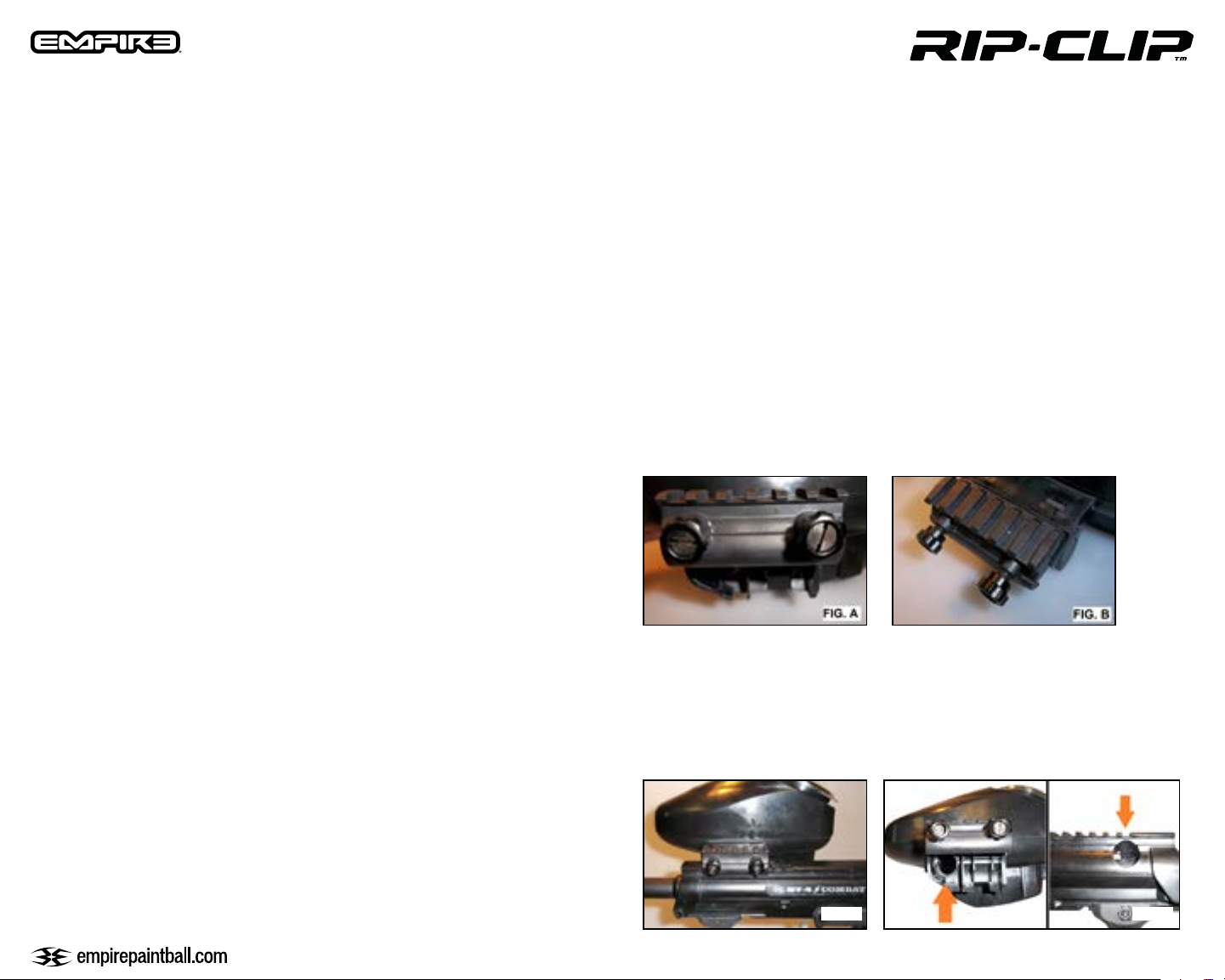
• Install the rail locking arm with screws and thumb nuts onto the Rip-Clip body using a flathead
screwdriver (Fig. A).
• Make sure the screws are fully seated into the body.
Rip-Clip Installation
• Loosen up the thumb nuts (Fig. B).
• Install the Rip-Clip onto the marker’s Picatinny rail (Fig. C).
• Check the position on the Picatinny rail and make sure the Rip-Clip is aligned with the feed hole
on the side of the marker (Fig. D).
• Tighten up the thumb nuts and you’re ready to go.
FIG.C FIG.D
3
Page 4
Battery Installation
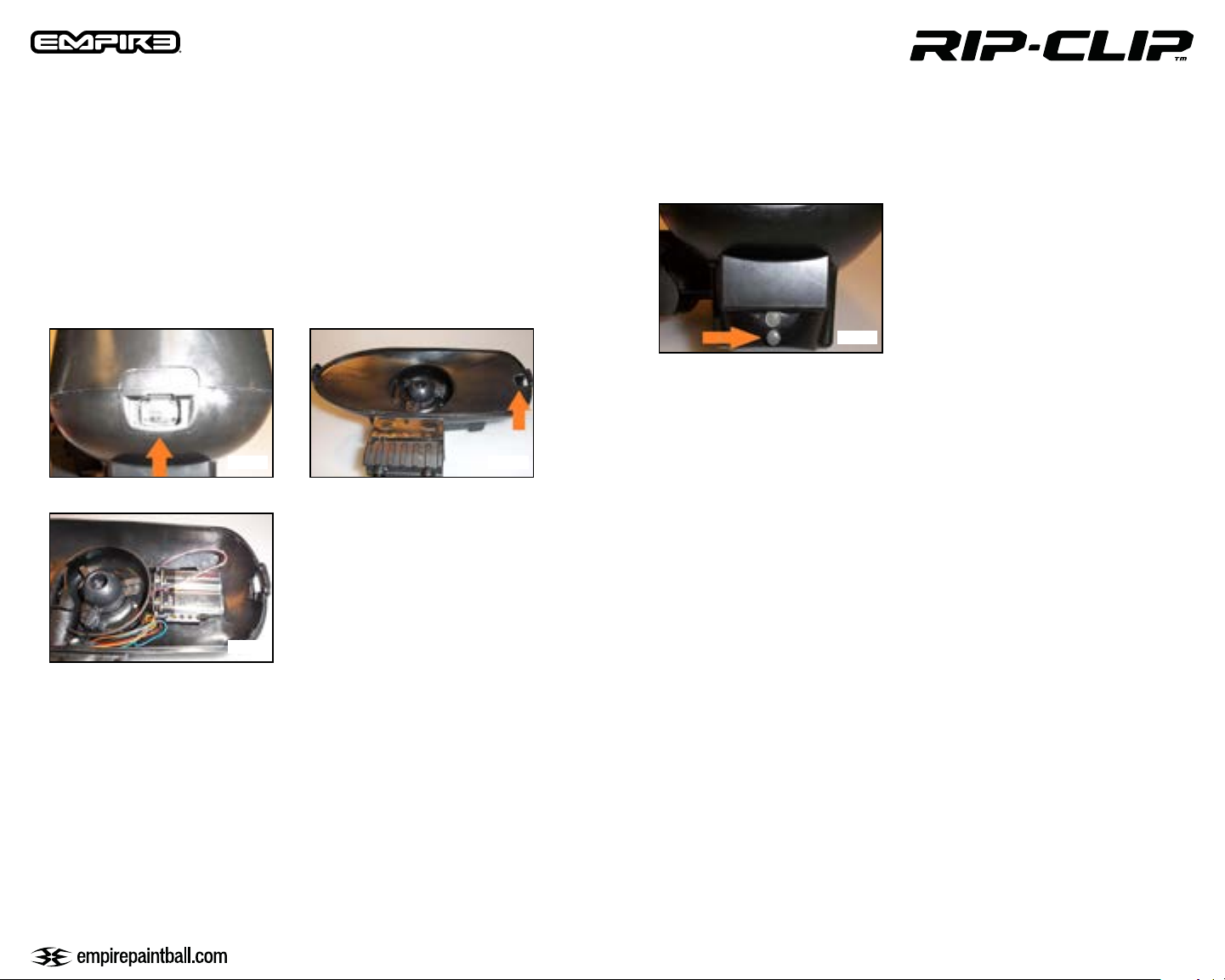
• Press and hold the Shell Release Button on the back of the loader (Fig. E) and pull the upper
shell apart from the lower shell.
• Pull the floor up and out of the lower shell (Fig. F)
• Install (2) 9-volt alkaline batteries into the battery harness (Fig. G).
• Place the batteries into the designated holder in the lower shell
• Replace the floor and the upper shell
NOTE: Use premium disposable alkaline or lithium batteries only in this loader for optimal performance. Rechargeable
batteries are not recommended. Used batteries should be recycled. Always replace both batteries at the same time
FIG.E
FIG.F
Activating the Rip-Clip
• Locate the power button on the rear of the Rip-Clip. Press and hold the power button until the
LED turns green to turn the Rip-Clip ON (Fig. H). The motor will spin to prime the marker and the
loader is now ready to use.
FIG.H
Normal Operation
• The green LED will flash repeatedly while the unit is on to show it is ready. If the LED flashing
changes to red, then the batteries are low and need to be replaced.
• Tap the power button while the loader is on to cause loader to feed immediately
• If the loader senses it is empty it will spin in short intervals for several seconds to attempt
to feed paintballs
• The rip-Clip may spin backwards if a jam is sensed (see “Auto Anti-Jam Function” section below)
• To turn off the Rip-Clip, press and hold the power button until the LED changes to Red. Release
the button and the loader will turn off. If the loader is left on, it will automatically shut off after
1 hour of inactivity.
FIG.G
Loading Paintballs
Open the spring loaded lid, load with .68 caliber paintballs, leaving some room for movement. Close
the lid by pressing it down until lid snaps shut.
CAUTION: Do not overfill the loader! This will cause impeller jams or performance
loss and could cause damage to the loader.
Note: Paintballs exposed to high temperatures and/or humidity can adhere to each other and will not feed through the
loader. Protect your paintballs from direct sunlight and high temperatures whenever possible.
Auto Anti-Jam Function:
The loader uses a break beam sensor at the feed neck to detect jams. If the loader senses shots 2 or
more times and doesn’t sense a ball in the break beam sensor the loader will attempt to un-jam. Once
un-jammed, the loader will automatically begin normal feeding again. Note: if you are encountering
jams repeatedly you should examine the loader for foreign objects or switch to fresher paintball
and/or batteries.
4. GENERAL MAINTENANCE
Emptying the Loader for Storage
With the loader turned OFF; turn it upside down to dump the paintballs out. Do not store your Rip
Clip loader with any paintballs remaining inside. When storing the loader for an extended period of
time, disconnect the battery harness from the batteries completely.
4
Page 5
Cleaning the Loader
To clean the loader, use only a clean, dry cloth, or apply a small amount of goggle lens cleaner to a
clean, dry cloth and wipe clean. Do not apply goggle lens cleaner directly to loader surfaces, as too
much contact will deteriorate plastic and cause damage.
If any paintballs break inside the hopper; do not use any liquids or chemicals to rinse out the
hopper; doing so will cause severe damage to the loader electronics.
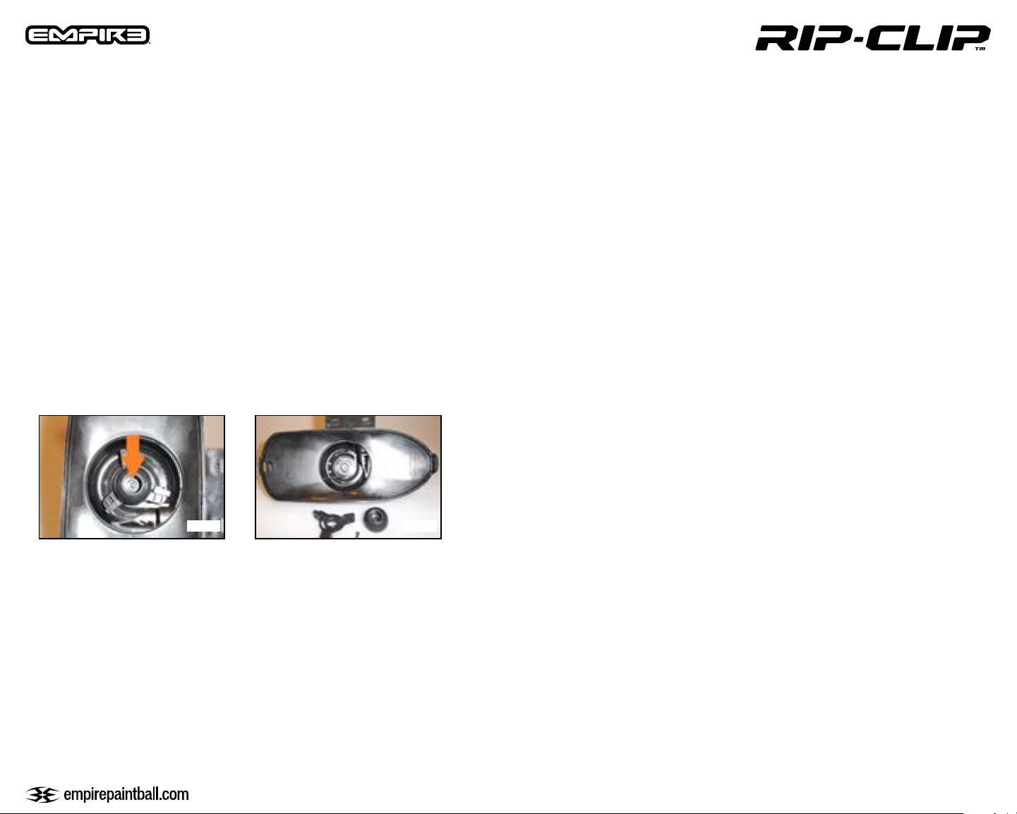
Impeller Disassembly/Reassembly
It is best to disassemble the loader before attempting to remove the impeller.
• Step 1. Remove impeller by using a Phillips head screwdriver. Use flat head screwdriver to lift
impeller base from the shaft. Rotate impeller and lift at several points under base (Dia. I).
• Step 2. Remove impeller top and arms from base. Clean and lubricate spring with marker grease
if necessary.
• Step 3. Reassemble spring to base tab as shown (Dia. J). Install impeller top and press on the
shaft to secure. Install Phillips screw and tighten. Test impeller for function before reassembly of
the loader. If the assembly does not spring back when under load disassemble for troubleshooting.
Reassemble with the above procedure.
Exiting Programming Mode
The loader will automatically turn off after 5 seconds of inactivity. To exit programming mode
simply don’t press the button for 5 seconds and the loader will turn off.
Navigating in Programming Mode:
Each setting is indicated by a different LED color
SPEED = GREEN
SOUND SENSITIVITY = RED
To navigate to the setting you would like to check or modify, tap and release the button until
the color corresponding to that setting is displayed. For example, if the LED is currently
GREEN corresponding to the SPEED setting, and your want to get to SOUND SENSITIVITY you
would press and release the button 1 times and the LED should display RED.
Checking and Changing Settings:
First press and release the button until you get to the color corresponding to the setting you want
to change. Once there press and hold the button for 3 seconds. The LED will begin blinking to
show the current value of the setting (for example if the led blinks 2 times the current value is Med).
Once done blinking, the LED will turn off and you have 3 seconds to begin entering the new value
by pressing and releasing the button. Once done entering the new value, release the button for 3+
seconds. The LED will flash alternate colors indicating the new value has been saved. The LED
will then go back glow the solid color corresponding to the current setting chosen.
FIG.I FIG.J
5. PROGRAMMING MODE
The loader has 2 settings that are adjustable by the user, which may be adjusted according to
playing conditions. The adjustable settings are Speed and Sound Sensitivity. Each setting has 3
levels; low, medium and high corresponding to 1, 2 or 3 blinks respectively.
To enter Programming Mode:
With loader OFF, press and hold the power button. The LED will then flash alternating colors
indicating you have entered the programming mode and you may now release the button. The LED
should now be GREEN to represent the Speed setting.
Note: If you just want to check the setting and not change it simply do not press the button to enter the new setting and
the setting will remain unchanged.
If you press and release the button more than the maximum value of the setting the maximum value
for that setting will be saved. For example if you enter a value of 5 for speed setting which has a
maximum value of 3, a value of 3 will be saved.
Programming Example – Changing sound sensitivity to 2 = Medium
-Enter programming mode as described above
- Press and release button until LED is RED
- Press and hold button until LED begins blinking
- Once LED turns off press and release button 2 times
-Wait until LED flashes alternate colors indicating setting is saved
- Wait until loader turns off automatically to exit programming
5
Page 6
SETTINGS EXPLANATION
Speed (GREEN LED)
This determines the maximum feed rate of the loader. Too low of a setting may cause inconsistent
feeding at high rates of fire. Too high of a setting may cause double feeding. 1 blink is slowest
speed and 3 blinks is the fastest.
1 blink = Low (best for markers with mechanical triggers or low rates of fire, less than 10bps)
2 blinks = Medium (Good for most markers)
3 blinks = High (Best for high speed electronic markers with anti-chop breech sensors)
Sound Sensitivity (RED LED)
This determines how sensitive the microphone will be to register a shot. Too low of a setting may
cause inconsistent feeding due to not sensing each shot. Too high of a setting may decrease
battery life by activating when not shooting. A setting of 1 blink is the least sensitive and 3 blinks is
the most sensitive.
1 blink = Low (best for louder mechanical markers such as the Empire BT-4 Combat Line)
2 blinks = Medium (good for most markers)
3 blinks = High (Should be used with very quiet electronic markers such as the Empire BT TM15)
6
Page 7
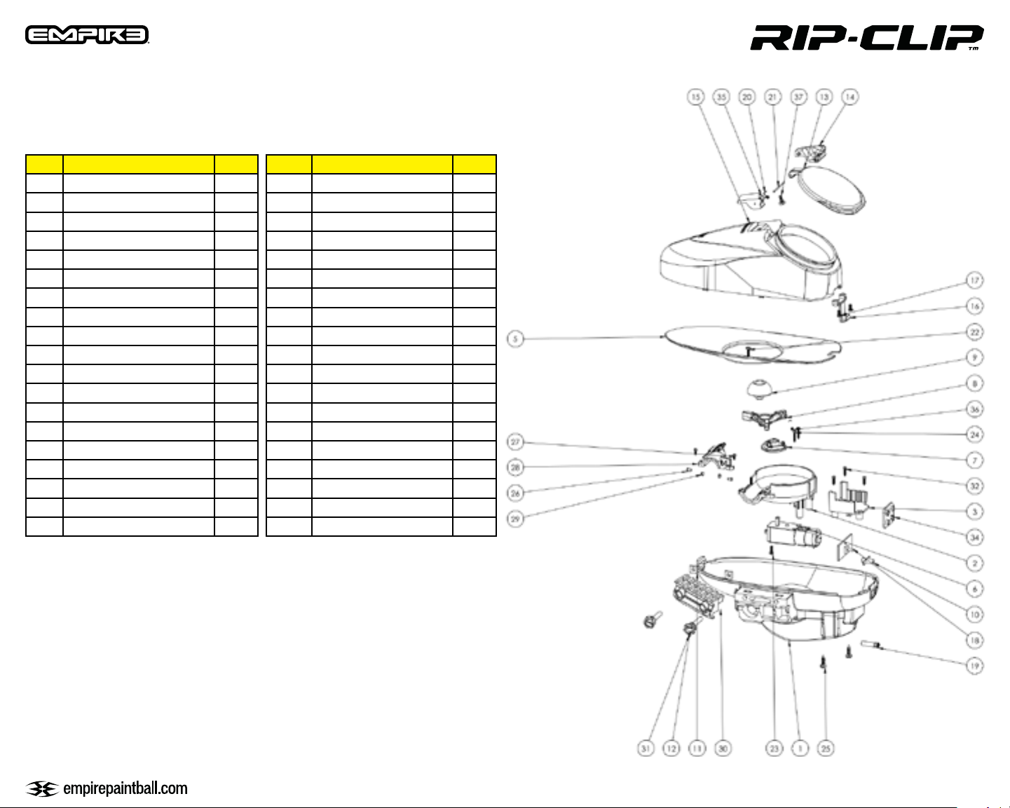
6. DIAGRAM AND PARTS
Dia.# Part SKU
1 Shell Bottom 70190
2 Catch Cup 70191
3 Battery holder 70192
5 Floor 70193
6 Motor Drive 30739
7 Impellor Blade Base 30 741
8 Impellor Blade 30740
9 Impellor Blade Top Cover 30 742
10 On/Off button 70194
11 Locking Rail Nut 38396
12 Rail Locking Thumb Nut 38433
13 Lid 38831
14 Lid Housing Right 70195
15 Top Shell 70196
16 Shell Lock 70197
17 Lock Screw 70198
18 Circuit Board 70199
19 Light Pipe 70200
20 Lid Spring 38833
Dia.# Part SKU
21 Lid Shaft 70201
22 Catch Cup Shaft Screw 70202
23 Motor Mount Screw 70214
24 Motor Screw 70203
25 Shell Bottom Screw 70204
26 Eye Harness 70205
27 Catch Cup Cover Screw 70206
28 Catch Cup Cover 70207
29 Sensor Cover 70208
30 Picitinny Locking Rail 38395
31a Rail Locking Screw Long TM Marker 38445
31b Rail Locking Screw Short BT4 Marker 38432
32 Battery Holder Screw 70210
34 Battery Harness 70211
35 Lid Housing left 70212
36 Impellor Spring 30738
37 Lid Screw 70213
Not Shown
Not Shown
TM-15 Adapter Plate 17852
TM-7 Adapter plate 38449
7
Page 8
Empire Paintball
11723 Lime Kiln Rd.
Neosho, MO 64850
www.empirepaintball.com
Empire Paintball is a brand of KEE Action Sports, LLC.
PATENT(S): See www.paintballsolutions.com/patents © 2014 KEE Action Sports. All rights
reserved. This KEE Action Sports product is protected by one or more United States patents. KEE Action Sports Trademarks, Designs and Copyrights are protected by one or more
United States patents and International Law. For more information contact KEE Action
Sports at [email protected]
LIMITED LIFETIME WARRANTY INFORMATION
KEE Action Sports (“KEE”) warrants that this product is free from defects in materials and
workmanship for as long as it is owned by the original purchaser, subject to the terms and
conditions set forth below. KEE Action Sports will repair or replace with the same or equivalent model, without charge, any of its products that have failed in normal use because of a
defect in material or workmanship.
KEE Action Sports is dedicated to providing you with products of the highest quality and the
industry’s best product support available for satisfactory play.
ORIGINAL PURCHASE RECEIPT REQUIRED
Purchaser should register product to activate warranty. Register your product by:
Online at www.paintballsolutions.com
WHAT THIS WARRANTY DOES NOT COVER
This warranty does not cover problems resulting from abuse, the unauthorized modification
or alteration of our product, problems resulting from the addition of aftermarket products
and scratches or minor superficial imperfections. Due to the nature of paintball products it
is important that the product be maintained by the user as indicated in the product manual
to remain in good operating condition. Your Limited Lifetime Warranty will be void if you fail
to maintain the product as recommended in the product instruction manual. In addition,
certain parts of a product may be subject to wear through regular usage. Replacement and
repair of such parts is the responsibility of the user throughout the life of the product. These
parts are not covered under the Limited Warranty. Examples of this type of part include (but
are not limited to) goggle lens, straps, O-Ring seals, cup seals, springs, ball détentes, batteries, hoses, drive belts, gears and any part of a product subject to continuous impact from
paintballs. Hydrotesting of air cylinders is not covered under this warranty.
The Limited Lifetime Warranty also does not cover incidental or consequential damages.
This warranty is the sole written warranty on KEE’s product and limits any implied warranty
to the period that the product is owned by the original purchaser. Some states, provinces
and nations do not allow the limitation of implied warranties or of incidental or consequential damages, so the above limitations or exclusions may not apply to you. This warranty
gives you specific legal rights and you may also have other rights which vary from state to
state, province to province, nation to nation. If you should encounter any problems with
your product and you have added aftermarket parts on your product, please test it with the
original stock parts before sending it in. Always unload and remove air supply before shipping markers. Do not ship your air supply tank if it is not completely empty. Shipping a pressurized air supply tank is unsafe and unlawful. Remove all batteries from products prior to
shipping. This Limited Warranty gives you specific legal rights, and you may also have other
rights which vary from state to state. Some states do not allow the exclusion of incidental
or consequential damages.
USA 800-220-3222
Canada 866-685-0030
For Warranty parts, service, information or manuals in other languages, (where applicable)
go to Paintball Solutions: www.paintballsolutions.com
E-Mail: [email protected]
US: 1-800-220-3222
Canada: 866-685-0030
11723 Lime Kiln Rd., Neosho, MO 64850
8
Page 9

11723 Lime Kiln Rd, Neosho, MO 64850
800-220-3222
Empire Paintball is a brand of KEE Action Sports, LLC.
 Loading...