

Page 1
• • • • • • • • • • • • • • • • • • • • • • • • • • • • • • • • •
Operating Instructions
for the
ProFormer
Pressure and Suction
TM
Cabinet System
• • • • • • • • • • • • • • • • • • • • • • • • • • • • • • • • •
2101 West Cabot Boulevard
Langhorne, PA 19047-1893
www.empire-airblast.com
Page 2

Empire Abrasive Equipment Company
Model Number: _______________________ Serial Number: ____________________________
Date of Purchase: ____________________ Date of Installation: _______________________
Distributor Purchased From:
Name: __________________________________________________________
Address: ________________________________________________________
Phone: _________________________________________________________
* * * * *
Manufactured by: EMPIRE ABRASIVE EQUIPMENT COMPANY
2101 West Cabot Boulevard
Langhorne, PA 19047-1893
Phone: 215-752-8800, Fax: 215-752-9373
Empire equipment should be properly maintained per the operating instructions. For
peak performance of your equipment, use only genuine Empire replacement parts;
accept no substitutes! The use of non-Empire parts will void the warranty.
PARTS AND SERVICE
1-800-497-4543
To order Empire replacement parts, contact your local authorized Empire distributor.
For the name of your local distributor, call Empire Customer Service, 1-800-497-4543,
or fax us at 215-752-9373, or e-mail us on our website www.empire-airblast.com and
we will call you back.
Never use silica-based abrasives
in Empire blast systems.
CAUTION
Page 2
Page 3

Empire Abrasive Equipment Company
Operating Instructions
for the
ProFormerTM Cabinet System
Suction and Pressure
Empire Abrasive Equipment Company
10/06/06
Page 3
Page 4

Empire Abrasive Equipment Company
Table of Contents
Table of Contents..................................................................................................... 4
Introduction............................................................................................................. 5
1.0 Installation ........................................................................................................ 6
1.1 Hand Tools Required ........................................................................................ 6
1.2 Preparing for Installation .................................................................................. 6
1.3 Getting Started................................................................................................. 6
TM
1.4 Positioning the ProFormer
1.5 Electrical Connections...................................................................................... 7
1.6 Compressed Air Connection............................................................................ 10
1.7 Earth Ground................................................................................................. 11
1.8 Installation Check .......................................................................................... 11
2.0 Equipment Operation ...................................................................................... 12
2.1 Loading Media ................................................................................................ 12
2.2 Start Up ......................................................................................................... 13
2.3 Blasting ......................................................................................................... 13
2.4 Dust Collector Cartridge Cleaning................................................................... 14
2.5 Equipment Shut Down ................................................................................... 14
3.0 Equipment Adjustments.................................................................................. 15
3.1 Suction System Media Flow Adjustment ......................................................... 15
3.2 Pressure System Media Flow Adjustment........................................................ 15
3.3 Reclaimer Adjustment .................................................................................... 16
4.0 Suggestions for Efficient Blasting ................................................................... 19
4.1 Media Selection and Use................................................................................. 19
4.2 Blast Pattern .................................................................................................. 20
4.3 Changing the Media ....................................................................................... 21
4.4 Pneumatic Controls ........................................................................................ 22
4.5 Helpful Hints for More Efficient Blasting ......................................................... 27
4.6 Cartridge Dust Collector Model SEM-2............................................................ 27
5.0 Maintenance .................................................................................................... 28
5.1 Daily Maintenance.......................................................................................... 28
5.2 Weekly Maintenance....................................................................................... 29
5.3 Storage or Temporary Non-Use ....................................................................... 30
6.0 Troubleshooting............................................................................................... 32
6.1 Troubleshooting Chart.................................................................................... 32
6.2 Troubleshooting the Pneumatic Control Circuit............................................... 35
7.0 Recommended Spare Parts.............................................................................. 38
8.0 Options and Accessories.................................................................................. 39
TM
9.0 ProFormer
Parts ........................................................................................... 41
9.1 Reclaimer ....................................................................................................... 41
9.2 Pressure Blast Systems .................................................................................. 42
9.3 Suction Blast Systems.................................................................................... 48
9.4 Dust Collector ................................................................................................ 50
9.5 Blowers (Fan & Motor) .................................................................................... 51
9.6 Ducting/Hoses ............................................................................................... 52
9.7 Pipe Strings.................................................................................................... 53
9.8 Basic Cabinet Assembly ................................................................................. 54
10.0 Warranty ........................................................................................................ 56
System ................................................................. 6
Page 4
Page 5
Empire Abrasive Equipment Company
Introduction
Congratulations on your selection of the ProFormer
Abrasive Equipment Company. This manual is provided to assist you with the
unpacking, assembly, use, and maintenance of your ProFormer
Please read this manual carefully and keep it in the handy plastic pouch attached to
your system for future reference. If you have any questions about the operation or
maintenance of your equipment, contact your Empire distributor.
™
Cabinet System from Empire
™
Cabinet System.
Empire: The leader in air-blast technology.
Empire specializes in the design and manufacture of air-blast equipment, and has
continued as an industry leader of more than 50 years. Today, Empire produces the
most extensive line of air-blast products in the world. In addition to ProFormer
®
systems, our product line includes Pro-Finish
Cabinets, ECON-O-FINISH™ Cabinets,
Modified Systems, Automated Blast Systems, Blast Rooms, and SuperBlast
Blasters.
Empire Abrasive Equipment Company’s reputation as a leader in air-blast technology
is the result of meeting our customer’s demand for quality equipment and systems
that deliver increased productivity. We support our equipment with training, service,
and testing programs. When you need advice, assistance, or equipment on short
notice, our national network of distributors assures that help is nearby.
™
™
Portable
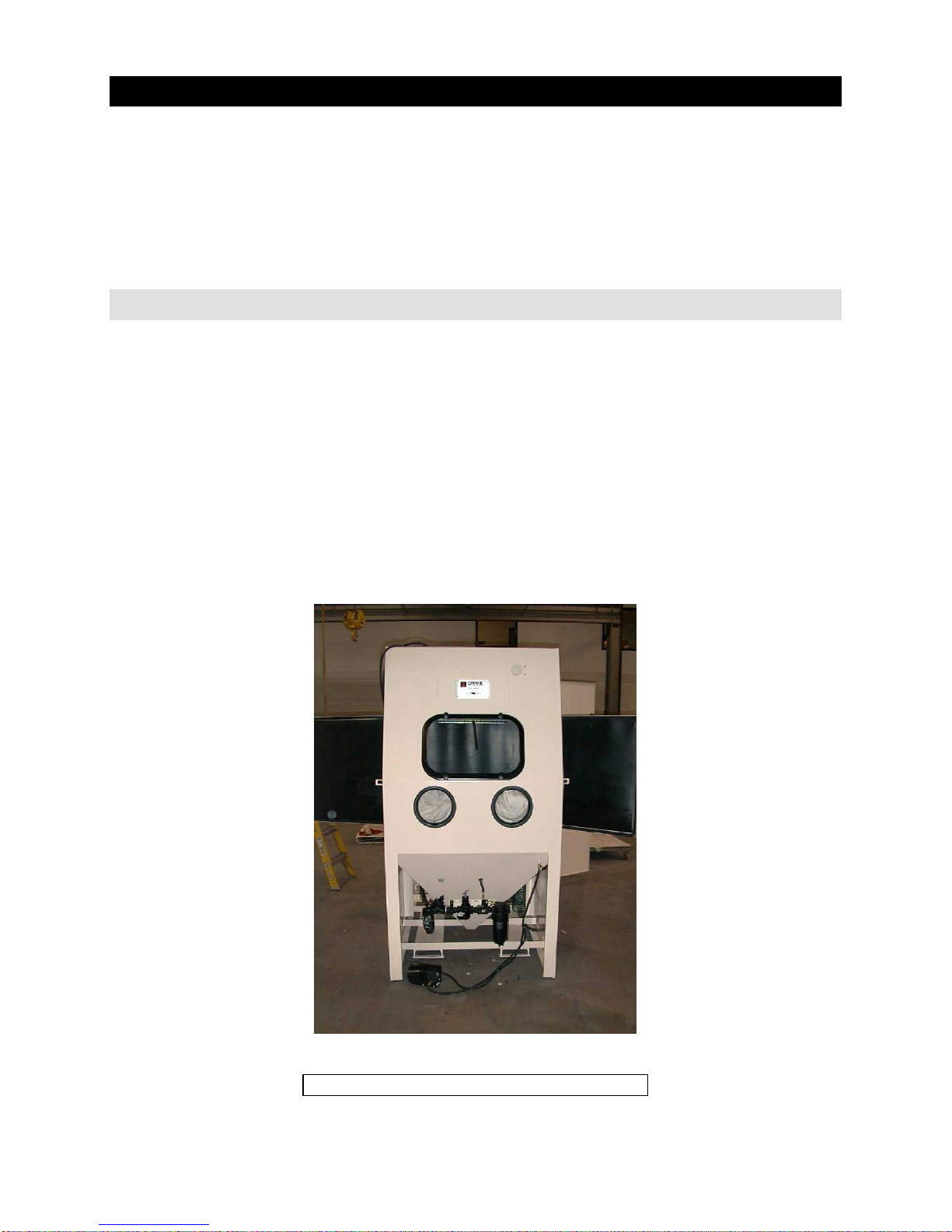
Figure 1. ProFormer
TM
Page 5
Cabinet System
Page 6

Empire Abrasive Equipment Company
1.0 Installation
1.1 Hand Tools Required
The following tools are recommended for the mechanical installation of your
™
ProFormer
Cabinet system:
• 6” adjustable wrench
• 9/16” wrench or socket
• 14” Pipe wrenches
• Channel Lock Pliers
• medium Phillips head screwdriver
• medium flat-blade screwdriver
1.2 Preparing for Installation
Your ProFormer
electric power are all that need to be connected. The equipment must be placed on a
level surface. Do not install your ProFormer
conditions.
™
system is fully assembled. Compressed air, earth ground, and
™
system on a floor subject to wet
1.3 Getting Started
Step 1: Unwrap and remove the cabinet from the pallet.
Step 2: Using the built-in forklift channels at the bottom of the cabinet, move the
system to the installation location.
Step 3: Insure there is adequate space on both sides of the cabinet for full opening of
part loading/unloading and maintenance access doors. PF3642 cabinets require 37
inches and PF 4652 cabinets require 44 inches on each side of the cabinet.
1.4 Positioning the ProFormerTM System
Step 1: Place the cabinet and stabilize it by adjusting the leveling bolts to compensate
for any unevenness in the floor.
Step 2: Insure that there is adequate space at both sides of the system for easy access
to components such as the reclaimer on the left hand side and the dust drum and
dust collector on the right hand side. There must be adequate space for work pieces
to be easily loaded and unloaded through the cabinet doors.
Step 3: Leave a space of 6 to 8 inches behind the cabinet for the compressed air
supply line. There is a 2 ½ inch hole provided on the bottom right side of the system
back wall for air supply line access.
Page 6
Page 7
Empire Abrasive Equipment Company
1.5 Electrical Connections
IMPORTANT
All electrical connections to the ProFormerTM cabinet should be made by a
qualified electrician and must adhere to the codes, standards, and procedures
specified by the authority having jurisdiction.
The customer is responsible for providing appropriate disconnecting means
adjacent to the equipment for each incoming power circuit.
The standard power supply for the ProFormer
240volts/60 cycle/single phase. Cabinets are also available pre-wired for the optional
power supplies listed in section 8.0 Options and Accessories.
The standard 220-240 volt single-phase system is supplied with a 10 foot, 4-wire line
cord which is connected to the cabinet light box. See Figure 3.
Canadian CSA approved single-phase cabinets have no line cord. Electrical
connections are made in the cabinet light box. See Figures 3.
All three-phase systems have no line cord. Electrical connections are made in the
transformer/contactor electrical box. See Figure 1.
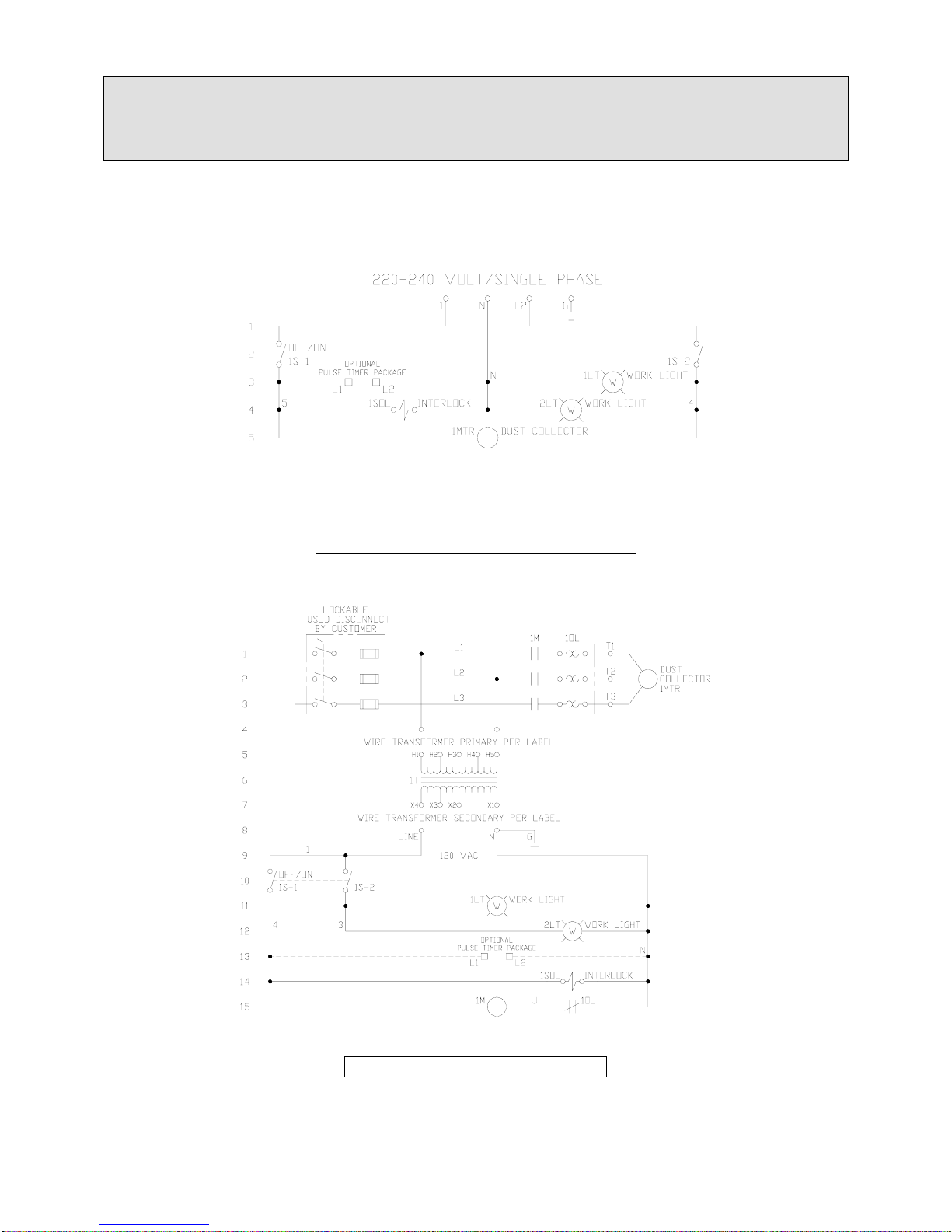
If your system is a three-phase power supply, wire the system as shown in Figure 5.
Use the adjacent tables for the approximate current draw in amps for the voltage of
your system.
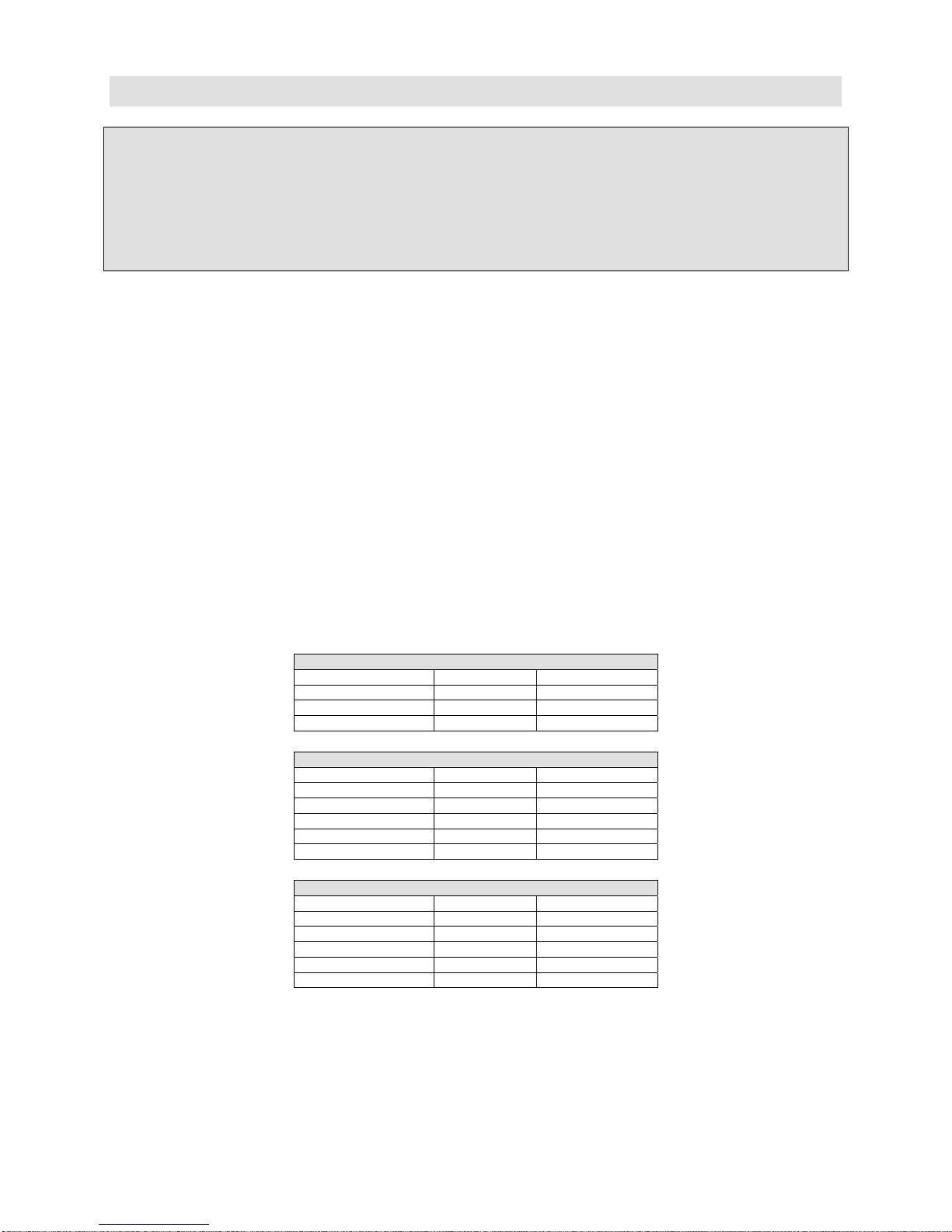
SINGLE-PHASE SINGLE SOURCE
SOURCE MOTOR CURRENT
110-120V/60HZ 1 ½ HP 23.0 A
220-240V/60HZ 1 ½ HP 13.0 A
220-240V/50HZ 1 ½ HP 15.0 A
THREE-PHASE SINGLE SOURCE
SOURCE MOTOR CURRENT
208V/60HZ 1 ½ HP 9.3 A
220-240V/60HZ 1 ½ HP 8.1 A
440-480V/60HZ 1 ½ HP 4.0 A
550-600V/60HZ 1 ½ HP 3.2 A
380V/50HZ 1 ½ HP 3.9 A
THREE-PHASE & SINGLE-PHASE DUAL SOURCE
SOURCE MOTOR CURRENT *
208V/60HZ 1 ½ HP 6.9 A
220-240V/60HZ 1 ½ HP 6.0 A
440-480V/60HZ 1 ½ HP 3.0 A
550-600V/60HZ 1 ½ HP 2.4 A
380V/50HZ 1 ½ HP 2.6 A
• The approximate single-phase current draw for all dual source systems is 3
amps at 110-120 VAC.
™
600 CFM, 1 ½ HP system is 220-
Page 7
Page 8
Empire Abrasive Equipment Company
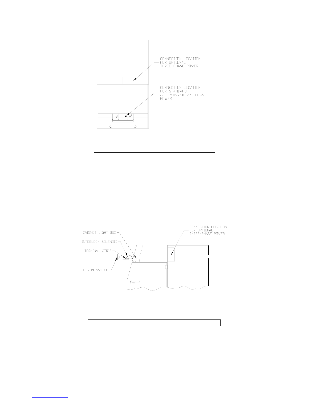
Figure 2. Electrical Connection Locations
The three-phase schematic shown in Figure 5 also appears on the back of the
transformer/contactor electrical box cover.
The 10 foot, 4-wire line cord is located above the cabinet light box. The single-phase
schematic shown in Figure 4 also appears on the back of the light box cover.
Figure 3. Single-Phase Terminal Board Access
For Canadian CSA approved single-phase cabinets, remove the four screws from the
cabinet light box cover. Move the cover to the side and pull the attached terminal
board plate from the light box as shown in Figure 3.
Page 8
Page 9
Empire Abrasive Equipment Company
IMPORTANT
Before connecting power, check that the voltage requirements of your
ProFormer system are consistent with the voltage available at the installation
site.
Figure 4. 220-240 Volt Single-Phase
Note: The transformer is not included with dual-source systems.
Figure 5. Three-Phase Option
Page 9
Page 10

Empire Abrasive Equipment Company
1.6 Compressed Air Connection
IMPORTANT
To operate properly, your ProFormerTM system requires clean, dry air. Moisture
or oil in the compressed air supply can contaminate the abrasive, which can
prevent it from flowing freely and cause inefficient blasting. Though your
system is equipped with a general-purpose filter to remove small amounts of
condensed water and oil from compressed air supply, this filter is not designed
to clean grossly contaminated air.
Step 1: Using the following two charts, determine the proper air volume needed for
your ProFormer
Step 2: The volume of air required for efficient operation of your system depends on
the size of the nozzle you are using and the desired blast pressure. The chart lists the
minimum air requirements in SCFM for various nozzles and pressures.
¼” nozzle, 1/8” air jet 12 17 21 26
5/16” nozzle*, 5/32” air jet 19 27 34 42
3/8” nozzle, 3/16” air jet 29 39 50 62
7/16” nozzle, 7/32” air jet 38 52 66 80
1/8” nozzle 10 14 17 20
3/16” nozzle* 22 30 38 45
¼” nozzle† 41 54 68 81
* Standard nozzle
† 3/4” blast hose option is recommended to reduce blast hose wear.
Step 3: Use the chart below as a guide to determine the size of the compressed air line
needed for your ProFormer
available, the supply air line to the system must be large enough to prevent friction
losses that create pressure drops which will reduce blast pressure and efficiency.
Step 4: The customer is to provide and install an air supply shut off valve. This
should be a three-way valve that will bleed off all trapped down stream compressed air
from the cabinet. The valve must also be able to be locked when closed.
Line Size (in) Length of Air Line (ft) Air Volume (SCFM)
™
system.
AIR REQUIREMENTS (SCFM) FOR SUCTION BLAST
40 psi 60 psi 80 psi 100 psi
AIR REQUIREMENTS (SCFM) FOR PRESSURE BLAST
40 psi 60 psi 80 psi 100 psi
™
system. Even when there is sufficient compressed air
¾ Up to 95 13 to 38
1 95 to 190 38 to 59
1-1/4 190 to 350 59 to 85
Page 10
Page 11

Empire Abrasive Equipment Company
1.7 Earth Ground
An Earth Ground stud is provided at the bottom right side on the enclosure back wall.
It is important to connect the ProFormer
™
system to an Earth Ground to bleed off
static electricity which may be generated while blasting. The Earth Ground may also
reduce the discomfort an operator may experience when static electricity is
discharged.
The Earth Ground conductors may be insulated or bare. Note that defects are more
easily detected during visual inspections of bare conductors.
The minimum wire size is dictated by mechanical strength rather than current
carrying capacity. Flexible conductors should be used when frequent connecting and
disconnecting of the Earth Ground is anticipated.
1.8 Installation Check
Step 1: Check that all pipe and hose connections are tightly fastened and air tight.
Check that all safety pins are properly installed in all quick couplings.
Step 2: Check that all electrical box covers are securely installed. Turn on the plant
compressed air supply to the system.
Step 3: Check that the dust drum under the dust collector has been installed
properly. It must be sitting squarely on the dust drum platform and centered under
the cover. Set the dust collector pulse pressure regulator to 40 psi. Check that the
optional fan silencer is fully opened.
Step 4: Turn the cabinet snap switch to the On position. The cabinet lights will
illuminate and the dust collector fan will start. Check that the fan is rotating in the
correct direction.
CAUTION
Disable and lock out power sources before performing service or maintenance
work. Do not look into the fan outlet to determine the correct motor rotation.
Check that the fan exhaust is clear of tools and free of debris before checking
fan rotation. To avoid personal injury, stay clear of the fan exhaust.
Step 5: Set the blast air pressure regulator to the desired pressure. The blast
pressure may be set as low as 20 psi, but do not exceed 125 psi.
Step 6: Insert both hands into the cabinet gloves and firmly grasp the suction gun or
pressure nozzle. Step on the foot treadle. The blast should start. After a few seconds,
the airflow from the nozzle will stabilize. Blast will stop when the foot treadle is
released.
Step 7: If applicable, press each dust collector pulse button once with the dust
collector on to insure pulse function.
The optional Photohelic control pulsing of the dust collector filters is automatic.
Adjust both red needles to below zero psi. The black needle must rise above both red
needles to activate the pulse. An increase in the gauge zero adjustment may be
required to test this function. After a successful test, the gauge setpoints should be
Page 11
Page 12

Empire Abrasive Equipment Company
set at a value of 2 psi for minimum, and 4 psi for the maximum pressure. When the
system is off, reset this gauge to zero.
Step 8: Turn the cabinet snap switch to the Off position. The cabinet lights will
extinguish and the dust collector fan will stop. The ProFormer
™
system is now ready
for media loading and part processing.
2.0 Equipment Operation
2.1 Loading Media
There are two methods for loading media into the ProFormer
the media level in the system before adding additional media. See section 4.1 for
Media Selection and Use.
The suction system hopper should be filled to the bottom of the reclaimer screen. The
pressure system vessel may be filled to the base of the sealing plunger.
Total media capacity by weight for the suction and pressure ProFormer
shown for popular media in the table below.
Method 1: With the cabinet switch OFF, media may be loaded through the removable
reclaimer access door. The reclaimer is located inside the left component access door.
After loading the media, reinstall the reclaimer door and insure an airtight seal.
Method 2: With the snap switch ON and the dust collector running, load media
through the media load station inside the right cabinet door. Place the appropriate
quantity of media between the cabinet cone and media load station baffle. The system
will slowly add the new media.
Glass Beads Aluminum Oxide Steel Shot or Grit
Suction 10 lb. 15 lb. 25 lb. 5 lb.
Pressure 75 lb. 100 lb. 200 lb. 30 lb.
IMPORTANT
Be careful not to overfill pressure systems. Overfilling will cause malfunction
and premature wear. See section 5.1 Daily Maintenance.
CAUTION
If your application requires aggressive media, such as aluminum oxide, garnet, or
steel grit, it is recommended that you use optional heavy-duty ducting,
reclaimer lining, and DI-CARB or BORON nozzles to prevent premature wear.
Empire strongly recommends using boron carbide nozzles when blasting with
Aluminum oxide, which is the most abrasive media.
If these options are not included with your system, they can be added. Optional
Rubber curtains for interior cabinet surfaces are also available. Consult your
Empire distributor for details.
™
system. Always check
™
system is
Walnut Shells or
Plastic
Page 12
Page 13

Empire Abrasive Equipment Company
2.2 Start Up
Step 1: Check that all pipe and hose connections are tightly fastened and air tight.
Check that all safety pins are properly installed in all quick couplings.
Step 2: Perform maintenance checks per section 5.0 Maintenance.
Step 3: Check that the dust drum under the dust collector is empty and has been
installed properly. It must be sitting squarely on the dust drum platform and centered
under the cover. The dust drum and cover must create an air tight seal.
Step 4: Turn on the plant compressed air supply. Turn the cabinet snap switch to the
On position. The cabinet lights will illuminate and the dust collector fan will start.
Step 5: Place the parts to be blast treated inside the blast cabinet. The parts must be
free of oil, grease, and moisture. Close and latch the cabinet load doors.
Step 6: Set the blast air pressure regulator to the desired pressure. Recommended
blast pressure ranges for various media types are listed in the table in section 4.1
Media Selection and Use. Do not exceed 125 psi blast pressure.
2.3 Blasting
Step 1: Insert each hand into a cabinet glove and grip the suction gun or pressure
nozzle assembly firmly. Aim the nozzle at the part to be blast treated.
Step 2: Step on the foot treadle to start the blast. After a few seconds the abrasive
flow will stabilize and you will be ready for blasting.
Step 3: Do not pump the foot treadle. It will decrease blast efficiency and cause
premature wear of system components.
Step 4: Hold the gun or nozzle at a 90-degree angle to the part at a distance that
produces the fastest results. This distance may vary from 3 to 18 inches, depending
on the work piece and the desired finish. See section 4.2 Blast Pattern.
Step 5: During the blasting process, periodically check the Minihelic pressure gauge
located above and to the right of the cabinet window. This gauge indicates the
condition of the filters. If the gauge pressure is 4 psi or greater, clean the filters as
outlined in section 2.4 Dust Collector Cartridge Cleaning.
Step 6: The reclaimer screen will require periodic cleaning. The frequency of cleaning
will depend on the volume of debris produced.
Step 7: For pressure systems, all the media in the pressure vessel will be used up
after an extended period of blasting. The operator must release the foot treadle to stop
the blast and depressurize the vessel. After a wait of approximately 2 minutes, media
will fill the pressure vessel and blasting can resume.
Step 8: When blasting of the part is complete, blast additional parts or follow the
instructions in section 2.5 Equipment Shut Down to shut the system down.
Page 13
Page 14

Empire Abrasive Equipment Company
2.4 Dust Collector Cartridge Cleaning
IMPORTANT
Never pulse clean the filters when the system is off. If dust is visible exiting the
dust collector fan housing, stop blasting and service the collector.
Pushbutton Control: During the blasting process, periodically check the Minihelic
pressure gauge located above and to the right of the cabinet window. This gauge
indicates the condition of the filters. If the gauge pressure is 4 psi or greater, the
filters must be cleaned. Press and release one pushbutton which will clean one of the
cartridges. Wait 10 seconds. Press and release the other pushbutton which will clean
the other cartridge. Continue this process alternating pushbuttons until the pressure
is reduced to 2 psi.
Photohelic Control Option: This option pulse cleans the dust collector filters
automatically when they need cleaning. The gauge high limit red needle must be set
at 4 psi as the maximum operating limit. The gauge low limit red needle must be set
at 2 psi as the minimum operating limit. The pulse pressure must be set at 40 psi.
IMPORTANT
Always use proper safety and protective equipment when disposing of collector
waste. Dispose of this waste properly.
WARNINGS
Explosive Dust: Explosive dust is generated from blast media, removed coatings
and substrates. An extreme concentration of dust may combust if ignited by
spark or flame. As a precaution, clean the system and empty the dust collector
often. Change media that has excessive dust concentration.
Emptying the Dust Collector: Always wear an appropriate dust mask when
emptying the dust collector and changing filters. Empty the dust collector daily.
2.5 Equipment Shut Down
Step 1: Release the foot treadle. The blast will stop. Remove the blast treated parts
from the blast cabinet.
Step 2: Check the Minihelic pressure gauge for the condition of the duct collector
filters. If the gauge pressure is 4 psi or greater, the filters must be cleaned. Press and
release one pushbutton which will clean one of the cartridges. Wait 10 seconds.
Press and release the other pushbutton which will clean the other cartridge. Continue
this process alternating pushbuttons until the pressure is reduced to 2 psi.
Step 3: Turn the cabinet snap switch to the Off position. Empty the dust collector
waste drum. Replace the drum squarely on the dust drum platform and centered
under the cover. The dust drum and cover must create an air tight seal.
Page 14
Page 15

Empire Abrasive Equipment Company
3.0 Equipment Adjustments
3.1 Suction System Media Flow Adjustment
The ProFormer
control the flow of media to the suction blast gun. The regulator is located at the
bottom of the storage hopper assembly inside the left component access door.
The amount of media entering the hose is controlled by how far the media hose is
inserted into the regulator. For normal operation, approximately ½ of the air inlet port
is blocked by the media hose. This may vary slightly when changing media size nozzle
size, and/or blast pressure.
To find a uniform media flow, loosen the thumbscrew and slide the media hose into
the SAR-2 regulator to increase and withdraw the hose to decrease media flow at the
nozzle. To determine if media is flowing, look through the media regulator air inlet
while the gun is operating. Listen for the sound of the blast to be smooth and
constant.
™
suction blast system is equipped with the SAR-2 media regulator to
3.2 Pressure System Media Flow Adjustment
The ProFormer
Regulator which is installed at the bottom discharge port of the pressure vessel. By
rotating the T-handle, media flow through the regulator and out of the blast nozzle
may be adjusted.
Step 1: Rotate the T-handle counter-clockwise until there is no resistance. Reverse
direction and make three full turns of the handle.
Step 2: As the T-handle is turned clockwise, the media flow through the regulator will
be reduced. While the system is blasting, make final adjustments in ½ turn, ¼ turn,
or 1/8 turn increments.
Optimum and most efficient blast is when the media exiting the blast nozzle is
just visible. Sure-Flo® Media Regulator adjustment may vary slightly when
media size, nozzle size, and/or blast pressure is changed. There are occasions
when blast pressure, media, and nozzle size requirements will not allow the SureFlo® Media Regulator to be properly adjusted to the desired media flow rate.
Refer to the tag attached to the regulator T-handle for additional instructions
and see section 4.0 Suggestions for Efficient Blasting for helpful hints.
™
pressure blast system is supplied with the patented Sure-Flo® Media
IMPORTANT
Page 15
Page 16

Empire Abrasive Equipment Company
3.3 Reclaimer Adjustment
All ProFormer
retained by the reclaimer. The reclaimer is supplied with a “tune-able” secondary air
adjustment. When the band is properly adjusted reusable media will be returned to
the media storage hopper. Unwanted dust and broken down media (fines) will be
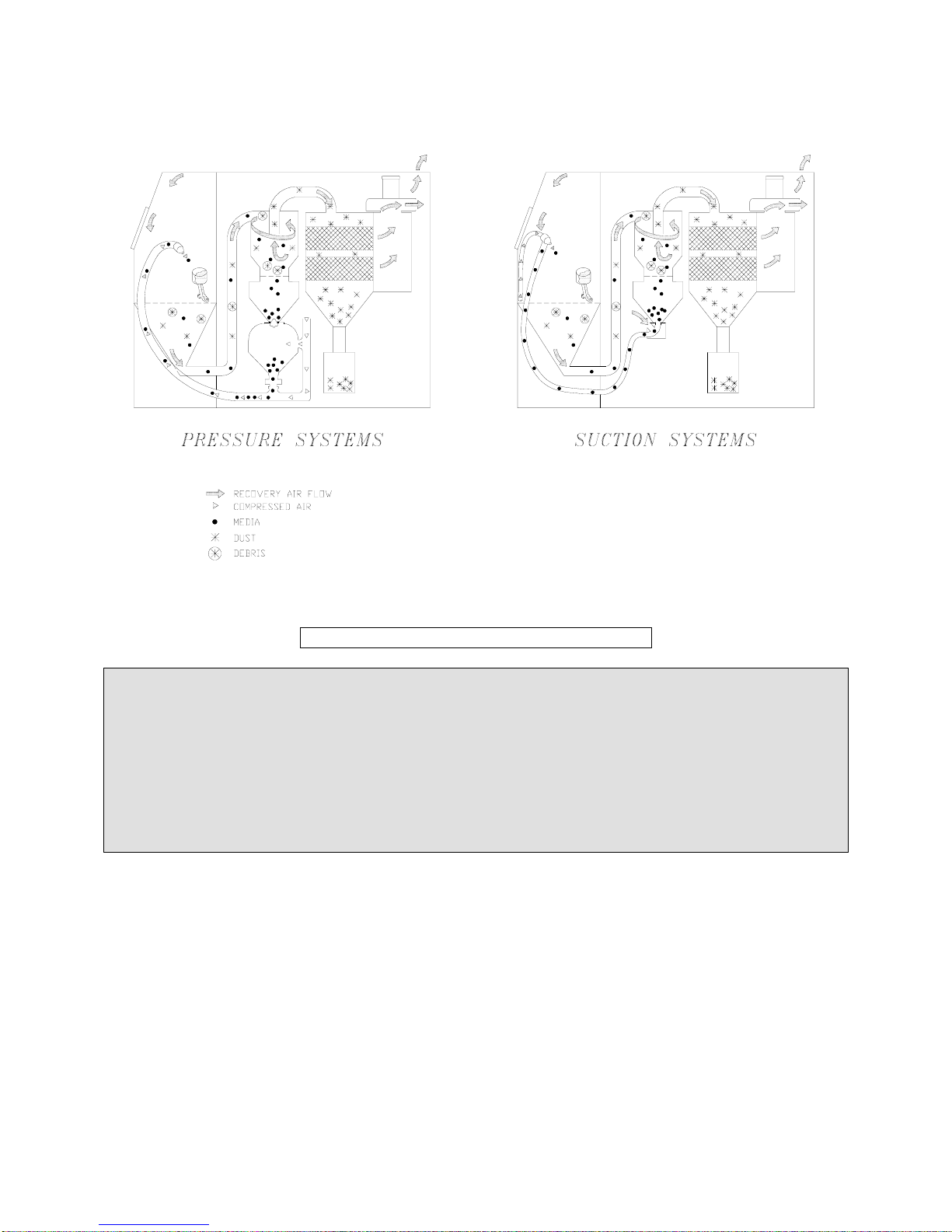
removed from the system and conveyed to the dust collector. See Figure 6.
Empire’s reclaimer design has vertical slots with a solid tuning band. The original
ProFormer
Fine tuning adjustments of both reclaimers are similar. Just remember to move the
band in the direction of the reclaimer slots; horizontal slots rotate the band, vertical
slots slide band up or down.
The tuning band is joined at both ends by a bolt and wing nut that must be loosened
before the band can be adjusted. The slot pattern around the reclaimer body has one
slot omitted. The joined ends of the tuning band must be located over the area of the
omitted slot.
Dust collectors require a coating of dust on the filter cartridges to achieve
maximum filter efficiency, also known as “seasoning”. The filters are seasoned
when the static pressure reading on the collector gauge is 2 or greater.
Step 1: Start with no reclaimer slots visible. Adjust the band in one direction until
1/16” of opening is created between the band and reclaimer slots.
Place a reference pencil mark on reclaimer body (and a corresponding reference
mark on the tuning band if horizontal slots).
Step 2: Operate the blast system for at least one hour.
Step 3: Turn the cabinet snap switch to OFF.
Step 4: Inspect the dust collector waste drum for reusable media.
Step 5: If no media is found in the waste, adjust the tuning band to expose 1/16”
more reclaimer body slot area.
Step 6: Make a new reference mark on the reclaimer body.
Step 7: Repeat Steps 2 through 7 until a small amount of media is found in the dust
collector waste. Adjustment is complete.
™
reclaimers can be adjusted to control the average size of media
™
reclaimers have horizontal slots in both the reclaimer and tuning band.
NOTE
HELPFUL HINT
Page 16
Page 17

Empire Abrasive Equipment Company
NOTE
As a new system is used, the filters become coated with dust, “seasoned” and the
airflow in the recovery system will decease to the normal operating rate. This
will affect previous reclaimer tuning band adjustments.
If visibility becomes poor inside the cabinet when blasting, there is too much dust
mixed with the blast media. The reclaimer tuning band should be re-adjusted.
Follow Step 2 though 7.
NOTE
For systems with large quantities of dust mixed with blast media, all dust and
media should be removed from the system and new media installed.
Step 8: If more than a small amount of media is found in the dust collector waste,
additional reclaimer tuning band adjustment may be required. Follow Steps 9
through 13.
Step 9: Adjust the tuning band back to the previous reference mark on the reclaimer
body, reducing the opening between the reclaimer and the band.
Step 10: After operating the blast system for at least one (1) hour, turn the cabinet
power switch OFF. Inspect the dust drum waste for reusable media.
Step 11: If no media is found in the waste, adjust the tuning band to expose 1/16”
less reclaimer body slot area.
Step 12: Make a new reference mark on the reclaimer body.
Step 13: Repeat Steps 8 through 13 until a small amount of media is found in the
dust collector waste. Adjustment is complete.
The schematic diagrams in Figure 6 illustrate:
(1) the basic operation of the system.
(2) the air and media flow before and after blasting.
Page 17
Page 18
Empire Abrasive Equipment Company
Figure 6. Blast and Recovery Operation
IMPORTANT
An insufficient volume of secondary air entering the reclaimer will cause dust to
accumulate with the “good” media in the storage hopper or pressure vessel.
This accumulation leads to inefficient blasting. Conversely, too much secondary
air will cause useful media to be carried to the dust collector and be wasted.
To avoid these conditions, adjust the tuning band to meet your specific blasting
requirements. When your system is new, it will be necessary to readjust the
tuning band periodically until the filters are “seasoned”.
Page 18
Page 19

Empire Abrasive Equipment Company
4.0 Suggestions for Efficient Blasting
4.1 Media Selection and Use
Proper media selection strongly influences the efficiency of your blasting operation.
Your choice of media depends on the kind of job to be done (cleaning, deburring,
smoothing sharp edges, paint removal, preparation for coatings, etc.) The size of the
media depends on the results you need.
Fine media results in more impacts per second over a given area. Therefore, fine
media is preferred for easy blasting jobs, such as the removal of light rust from steel.
Large media results in fewer impacts, but each impact has more force, so that large
media is more suitable for difficult jobs, such as removal of mill scale. Sometimes
large and find media may be combined for optimum results.
The chart below lists the range of media recommended for each ProFormer
System. Certain media, such as sand and slag, are not to be used in ProFormer
cabinets, both for health reasons and because they pulverize on impact and cannot be
recirculated.
Media Type
Media Size
Aluminum Oxide
46 to
80
Mesh
or
Garnet
100 to
300
Mesh
Glass Beads Steel Grit Steel Shot
25 to
180
Mesh
200 to
300
Mesh
G-16
to
G-50
G-80
to
G-200
S-390
to
S-170
S-110
to
S-70
™
Blast
Walnut
Shells
Plastic
Any
Size
™
or
Suction R R* R R* NR R NR R R*
Pressure R R** R R** NR R NR R R**
R – Recommended. * Recommended optional vibrating screen for mesh sizes 200 to 300 or when high humidity is a problem.
NR – Not Recommended. ** Recommended optional vibrating screen and aerated media regulator for mesh sizes 200 to 300.
Spherical media, such as glass beads, are used for general purpose cleaning and
finishing where a satin-like finish is desired with little dimensional change. Glass
beads are effective when used with pressures in the 20 to 60 PSI range. Above 60 PSI,
excessive bead breakdown will occur.
Angular aggressive media, such as aluminum oxide, steel grit, and garnet generally
provide faster cleaning and produce a less-polished finish compared to glass beads.
Aluminum oxide and steel grit are suitable for use at pressures up to 100 PSI. Garnet
breaks down quickly at pressures greater than 40 PSI.
Walnut shells or plastic are sometimes used for delicate parts, paint removal, or when
a polished finish is required. Pressures from 20 to 100 PSI may be used with these
media, depending on the application.
When changing from one type of media to another, clean the cabinet interior and
media hoses thoroughly to avoid cross contamination.
Page 19
Page 20
Empire Abrasive Equipment Company
CAUTION
If your application requires aggressive media, such as aluminum oxide, garnet, or
steel grit, it is recommended that you use optional heavy duty ducting,
reclaimer lining, and DI-CARB or BORON nozzles to prevent premature wear.
Empire strongly recommends using boron carbide nozzles when blasting with
Aluminum oxide, which is the most abrasive media.
If these options are not included with your system, they can be added. Optional
Rubber curtains for interior cabinet surfaces are also available. Consult your
Empire distributor for details.
4.2 Blast Pattern
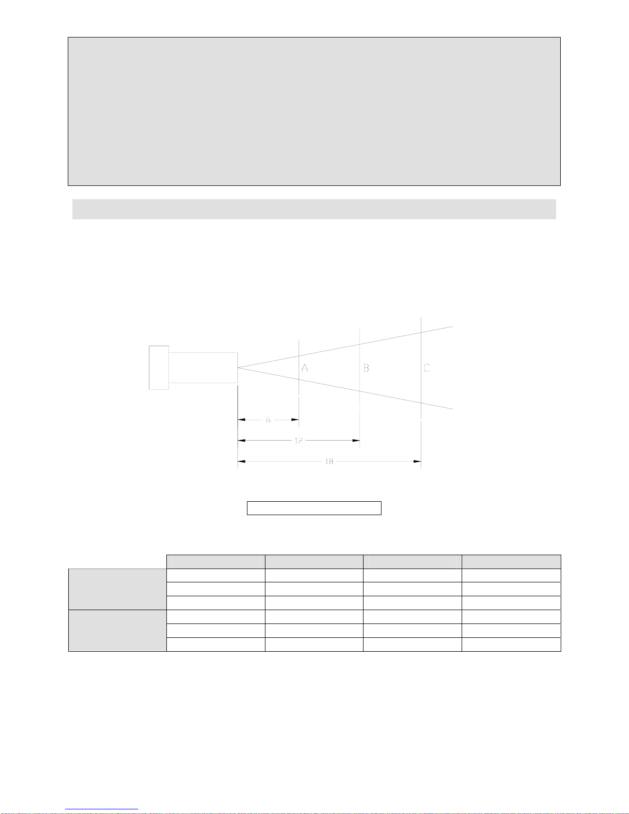
The size of the effective blasting pattern varies with the size, type and length of the
nozzle, blast air pressure, and the nature of the work piece. Use the following chart
and diagram as a guide, but be aware that the approximate pattern diameters can
only be determined by considering each case individually.
Blast Pattern Diameter at Distance Listed
Nozzle ID A B C
¼ ¾ 1 ¼ *
Suction Blast
5/16 1 1 ½ *
7/16 1 1/8 1 ¾ *
1/8 ¾ 1 ¼ 2 ¼
Pressure Blast
3/16 1 1 ½ 2 3/8
¼ 1 1/8 1 ¾ 2 1/2
Suction Blast at a distance of greater than 12” is usually not effective.
Figure 7. Blast Pattern
Page 20
Page 21

Empire Abrasive Equipment Company
4.3 Changing the Media
When changing from one type or size of media to another, it can be extremely
important to clean out the blast and recovery hoses, storage hopper, pressure vessel,
and the cabinet interior thoroughly to avoid contamination of the new media.
IMPORTANT
Always use proper safety and protective equipment when disposing of collector
waste. Dispose of this waste properly.
Suction System
Step 1: Turn the ProFormer
and locate the reclaimer, media storage hopper, and SAR-2 media regulator.
Step 2: Using proper safety and protective equipment, place a container, such as a
bucket, directly under the storage hopper and SAR-2 regulator. Loosen (do not
remove) the 7/16” nut at the bottom of the regulator plug. Pull down on the plug
removing it from the regulator. This will allow the media to empty from the storage
hopper into the container.
Step 3: Turn the ProFormer
Insert each hand into a cabinet glove and grip the suction gun firmly. Aim the nozzle
toward the back of the blast cabinet and press the foot treadle. Blast for 30 seconds
to remove all media from the suction hose and gun assembly.
Step 4: Release the foot treadle. Using proper safety and protective equipment, open
one of the part loading doors and use the Blowoff gun to remove the media from ledges
and surfaces into the cone for recovery.
Step 5: Turn the ProFormer
SAR-2 drain plug, and close the reclaimer door. Dispose of all waste properly.
Step 6: The system is ready for new media. Refer to section 2.1 Loading Media,
section 3.1 Suction System Media Flow Adjustment, and section 3.3 Reclaimer
Adjustment.
Pressure System
Step 1: Turn the ProFormer
and locate the reclaimer, media storage hopper, and pressure vessel.
Step 2: Adjust the T-handle of the Sure-Flo® grit valve counter clockwise, fully
opening the regulator. Close the 1” ball valve (choke valve) located on the pressure
vessel pipe string assembly. Fully open the reclaimer tuning band.
Step 3: Turn the ProFormer
pressure nozzle and nozzle washer from the end of the blast hose. Place a container,
such as a bucket, inside the blast cabinet. Place the blast hose inside the container
and close and latch the part loading doors.
™
system off. Open the left side equipment access door
™
system on. Close and latch the part loading doors.
™
system off. Clean both reclaimer screens, reinstall the
™
system off. Open the left side equipment access door
™
system on and open a part loading door. Remove the
Page 21
Page 22

Empire Abrasive Equipment Company
Step 4: Adjust the blast pressure regulator to 40 psi. Insert each hand into a cabinet
glove and grip the blast hose firmly. Aim the hose into the container and press the
foot treadle. Blast for 30 seconds to remove all media from the blast hose.
Step 5: Turn the ProFormer
™
system off. Clean both reclaimer screens, readjust the
Sure-Flo® grit valve, and close the reclaimer door. Dispose of all waste properly.
Step 6: The system is ready for new media. Refer to section 2.1 Loading Media,
section 3.2 Pressure system Media Flow Adjustment, and section 3.3 Reclaimer
Adjustment.
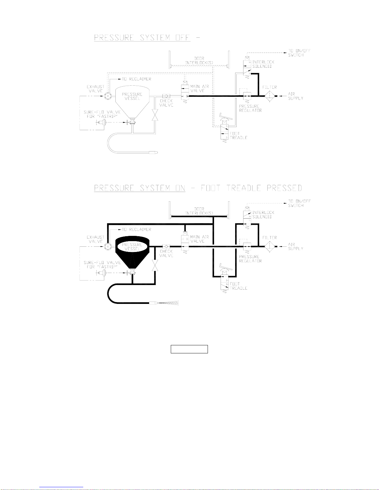
4.4 Pneumatic Controls
The ProFormer
workers environment, and activate the blast.
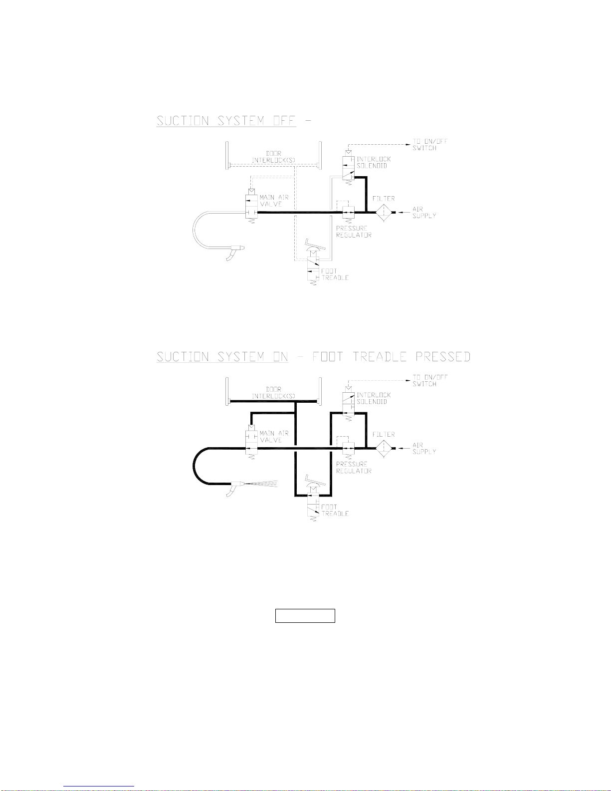
Step 1: Turning the system snap switch on energizes the interlock solenoid valve,
permits air to enter the control air line to the foot treadle, illuminates cabinet lights
and start the fan motor.
Step 2: The operator steps on the foot treadle opening a three way control air valve.
Air enters the door interlock supply tubing continuing to the door air jets. If the part
load/unload doors are closed, latched, and door air jets are sealed, the control air
lines pressurize and open the main blast air valve (and the pressure systems exhaust
valve to close). The opening of the main air valve starts the blast.
Step 3: When the operator removes his foot from the foot treadle, the three way air
valve close, shutting off air to the controls, and exhausting all down stream air. The
control air line pressure bleeds from the door interlock supply tubing, main blast air
valve (and the pressure system exhaust valve). This permits the main blast air valve
to close (and the pressure system exhaust valve to open) stopping the blast.
Step 4: When a part load/unload door is opened, the pad covering the door interlock
air jet is unseated. When the foot treadle is pressed with a door open, control air
bleeds from the door air jet opening, preventing the control circuit from pressurizing.
The main blast air valve will not open, and blasting will not occur.
™
system uses a patented pneumatic control circuit to protect workers,
Page 22
Page 23
Empire Abrasive Equipment Company
The following schematic diagrams illustrate the pneumatic control circuits for suction
systems (Figure 8A) and pressure systems (Figures 8B). For each system type, the
cabinets are shown in blasting and non-blasting modes (shaded pipe is pressurized).
Figure 8A.
Page 23
Page 24
Empire Abrasive Equipment Company
Figure 8B.
Page 24
Page 25
Empire Abrasive Equipment Company
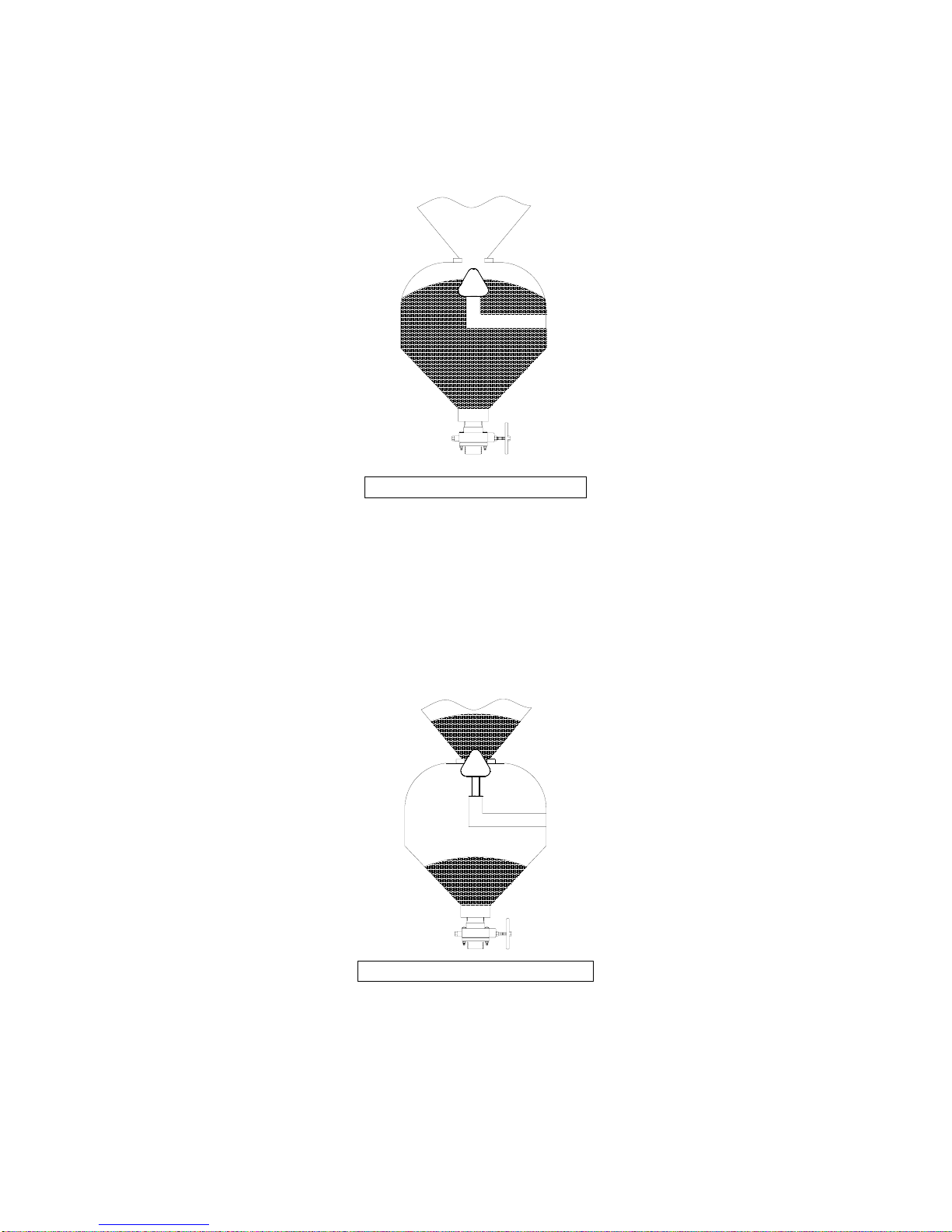
The following drawings show media flow through a typical pressure system and are
provided to help you understand how to maintain the media at the proper level.
Pictured at right is a fully charged system with the vessel depressurized (no blasting).
Note that the media fills the pressure vessel but that there is not media in the storage
hopper.
Figure 9. Before Blasting
When blasting starts, the vessel pressurizes, the media impacts the part being blasted,
and reusable media is recovered and accumulates in the storage hopper. Continuous
blasting time is limited by the type and amount of abrasive in the in the vessel when
blasting starts (normally 8 to 15 minutes with a fully charged 1 cubic foot vessel,
depending on nozzle size and blast air pressure). Each time the operator stops
blasting, the vessel de-pressurizes and the sealing plunger drops. Media in the
storage hopper flows into the vessel. If blasting is stopped long enough (usually 1-2
minutes), all media in the storage hopper will transfer into the pressure vessel.
Figure 10. During Blasting
Page 25
Page 26
Empire Abrasive Equipment Company
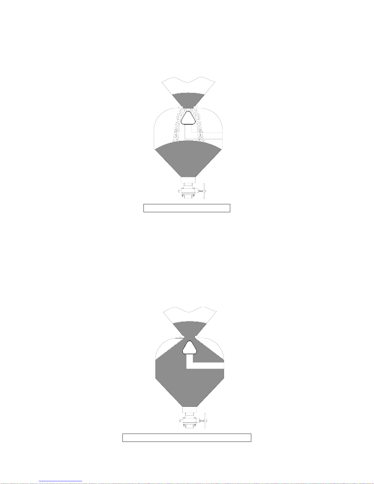
Thus, you can determine the amount of media in the vessel in either of two ways: (1)
note how much continuous blast time you can achieve with a fully charged vessel and
compare this with your current continuous blast time; or (2) stop blasting, open the
reclaimer door, and visually determine the media level by looking into the top of the
vessel.
Figure 11. After Blasting
Overfilling pressure vessels will cause improper operation and premature wear. Allow
sufficient time after blasting for the pressure vessel to refill (2 minutes). When the
pressure vessel is filled, check to see if any media has remained in the storage hopper,
indicating that the vessel is overfilled, the sealing plunger may not seat tightly when
you start blasting.
See section 5.3 Storage or Temporary Non-Use for instructions on how to empty the
pressure vessel.
Refer to section 2.1 Loading Media for instructions to add media.
Figure 12. Pressure Vessel Overfilled
Page 26
Page 27

Empire Abrasive Equipment Company
4.5 Helpful Hints for More Efficient Blasting
The efficiency of your blasting operation depends on four factors:
1) Equipment selection
2) Media selection
3) Operating procedures
4) Maintenance
With the help of your Empire Distributor and/or Empire factory representative, you
now own equipment that will properly meet your blasting requirements.
You can select the proper media, operating procedures, and maintenance steps by
following the recommendations in this manual. If you need more information about
any aspect of your machine’s operation or the blasting process, contact your local
distributor or the factory.
The following measures will also help you improve the efficiency of your blasting
operation:
Step 1: To accomplish more in less time, use the largest nozzle practical for your
operation. Of course, nozzle diameter may be limited by the amount of compressed air
available, but an increased volume of compressed air is often justified by reduced
labor costs. Also, if you are blasting small parts, it doesn’t make sense to use a big
nozzle, as most of the blast pattern will be overspray.
Step 2: For faster cleaning, use the highest pressure practical for your operation.
Maximum pressure for a given operation is limited by type of media (e.g. glass beads
can break down rapidly above a certain pressure) and amount of material which must
be removed from the workpiece.
Step 3: If you are blasting small parts, it may be more efficient to manipulate the part
with tow hands and use an optional fixed nozzle holder.
Step 4:
Never underestimate the importance of clean, dry air.
problems are traceable to the lack of clean dry air than any other single factor. If the
supply air is not clean and dry, media quickly becomes contaminated, causing flow
problems, which wastes media and leads to excessive operator downtime.
More operational
4.6 Cartridge Dust Collector Model SEM-2
Additional information about the operation of the ProFormer
can be found in the collector Installation and Operation Manual. This manual can be
found inside the left maintenance access door in an envelope attached to the inside
left rear wall of the system.
Page 27
™
Cartridge Dust Collector
Page 28

Empire Abrasive Equipment Company
5.0 Maintenance
5.1 Daily Maintenance
Step 1: Turn the cabinet snap switch on.
Step 2: Remove the accumulated dust from the dust collector drum and the debris
from the reclaimer screen.
Step 3: Check the condition of the media. If the media is contaminated or broken
down into dust, thoroughly clean the inside of the cabinet and recovery system and
reload with new media. See section 2.1 Loading Media.
Step 4: Adjust the reclaimer tuning band if you observe a dusty condition when
blasting. See section 3.3 Reclaimer Adjustment.
Step 5: Check the media level. For optimal operation, the media level should not drop
below one-half the recommended capacity.
A. The media level in suction systems can be observed in the media storage
hopper.
B. The media level in pressure systems can be observed by looking through the
optional sight glasses or the reclaimer door down into the top of the vessel.
When the vessel is de-pressurized, the sealing plunger must be visible. Add
media until just visible below the sealing plunger.
Step 6: Check light bulbs and gloves. Replace as required.
Step 7: Open the manual drain on the general-purpose filter in the cabinet pipe string
and drain any accumulated moisture and oil. Close the drain and dispose of the
waste properly.
Step 8: All quick coupling connections must be equipped with safety pins. Inspect all
couplings and blast hoses daily for splits, bubbles, soft spots, etc. Screws should be
flush with coupling surfaces. Tighten screws, if necessary.
Page 28
Page 29
Empire Abrasive Equipment Company
5.2 Weekly Maintenance
CAUTION
If your application requires aggressive media, such as aluminum oxide, garnet, or
steel grit, it is recommended that you use optional heavy duty ducting,
reclaimer lining, and DI-CARB or BORON nozzles to prevent premature wear.
Empire strongly recommends using boron carbide nozzles when blasting with
Aluminum oxide, which is the most abrasive media.
If these options are not included with your system, they can be added. Optional
Rubber curtains for interior cabinet surfaces are also available. Consult your
Empire distributor for details.
Step 1: Repeat the daily maintenance procedures.
Step 2: Inspect all media-carrying hoses for wear by feeling along the length of the
hose for soft spots. Hoses with soft spots should be replaced.
Step 3: Check the nozzle for wear. When the nozzle is worn 1/8” oversize, replace it.
A drill bit can be inserted into the nozzle to check its size.
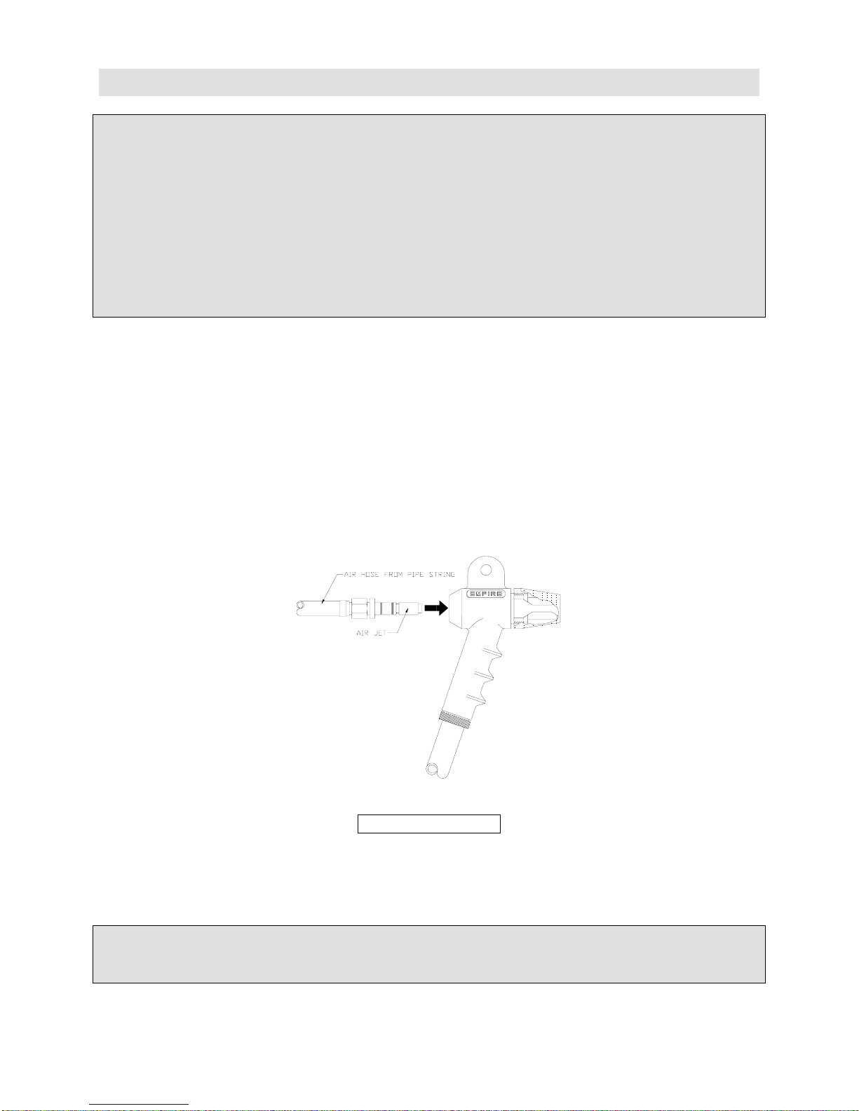
Step 4: On suction systems, check the air jet for wear.
Step 5: Loosen the set screw in the side of the gun body and remove the air jet. See
Figure 13.
Step 6: If the air jet shows wear, rotate it 90° and reinsert it into the gun.
Step 7: Re-tighten the set screw.
If an air jet is allowed to wear completely through, it will cause premature wear
of the gun body and nozzle.
Step 8: Check the nozzle adapter and gun body for wear. Replace if necessary.
Step 9: Check the window gaskets for leaks. Replace if necessary.
Figure 13. Air Jet
IMPORTANT
Page 29
Page 30
Empire Abrasive Equipment Company
Step 10: Check your spare parts inventory. Ensure that you have an adequate supply
of replacement items.
5.3 Storage or Temporary Non-Use
If your ProFormer
steps to remove media and prevent media from caking inside the system:
Step 1:
• Suction systems:
Empty media from the cabinet and storage hopper. To remove the media from the
storage hopper: remove the rubber plug from the bottom of the SAR-2 regulator.
• For pressure systems:
A) Reduce blast pressure to 40 PSI.
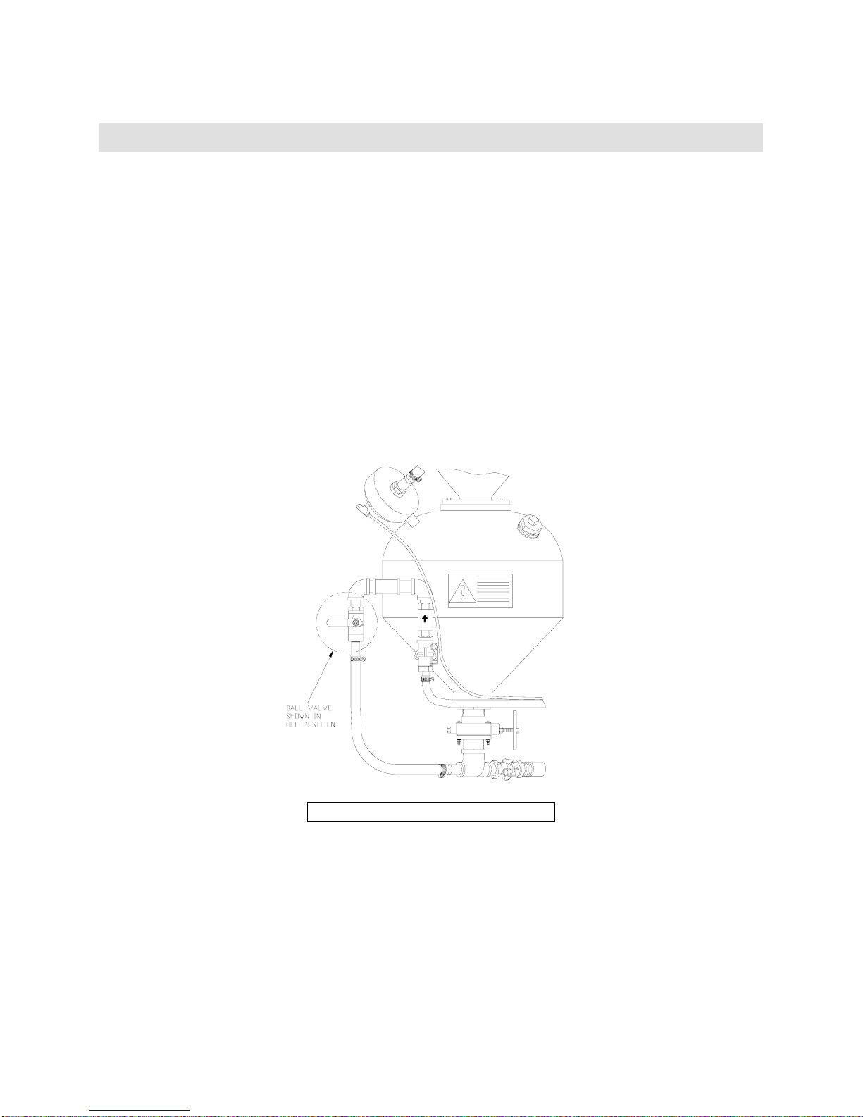
B) Close the choke (ball) valve on the pressure vessel pipe string. (See Figure 14).
™
system will not be used for several days (or more), follow these
Remove the blast nozzle and washer from the blast hose.
C) Pressurize the vessel as if to blast.
These steps will cause the media to flow from the open end of the blast hose in a
controlled manner. The media can now be directed into a suitable container or
receptacle.
After the pressure vessel is empty:
D) Open the choke valve.
Figure 14. Closed Choke Valve
Page 30
Page 31

Empire Abrasive Equipment Company
E) Replace the nozzle washer and nozzle.
F) Return the blast pressure setting to normal.
Step 2: Drain the general purpose filter. Close the drain valve.
Page 31
Page 32
Empire Abrasive Equipment Company
6.0 Troubleshooting
6.1 Troubleshooting Chart
Problem: Good media is being carried to the dust collector.
Probable Cause Remedy
Problem: Media is escaping into the work area from the dust collector.
Probable Cause Remedy
Hole in dust filter(s)or
Problem: Poor visibility during blasting.
Probable Cause Remedy
New filters. Continue use until filter “cake” forms
(approximately eight hours of
operation).
Tuning band is open too
Adjust tuning band.
far.
Insufficient media in
suction hopper allows
Add media to recommended media
level.
secondary air to enter.
Media too fine. Use more coarse media.
Pressure systems: Worn
Replace plunger and/or sealing ring.
plunger or sealing ring
leaking air into reclaimer.
Replace leaking filter(s)or refasten
loose filter(s).
Reclaimer not adjusted
properly.
filter(s).
Adjust reclaimer air inlet settings
See section 3.0 Equipment
Adjustments.
Clogged dust bag(s). Shake dust bag or dust collector bags.
“Blinded” filters (reduced
air flow due to age of the
filters).
Over a period of years dust may
penetrate the dust filter to the extent
that normal air flow is restricted even
when filters are pulsed regularly.
When this condition is reached,
replace the filters.
Fan rotation backwards. Reverse the fan rotation.
Media has high dust
content.
Replace media and adjust reclaimer
tuning band.
Recovery hose blocked. Remove hose, inspect and remove
obstruction.
Cabinet air inlet plugged. Blow filter clean with air line.
Dust collector door leaks
air.
Blast nozzle or air jet too
large.
Tighten door, replace gasket if
necessary.
Replace worn nozzle with
recommended size: maximum ¼”
diameter pressure, maximum 7/32”
air jet for suction.
Operating air pressure too
high.
Decrease pressure to within
recommended range.
Page 32
Page 33
Empire Abrasive Equipment Company
Problem: No air or media flow from the nozzle.
Probable Cause Remedy
Compressed air line shut
Open all air valves from compressor.
off.
Cabinet Doors not tightly
closed.
Close cabinet doors sealing door
interlock.
Regulator adjusted to zero. Adjust regulator.
Nozzle clogged. Disassemble and clean nozzle.
Door interlock air hose
leaking.
Replace hose. If problem continues,
see section 6.2 Troubleshooting the
Pneumatic Control Circuit.
Problem: Poor production rate.
Probable Cause Remedy
Low blast air pressure. Increase pressure within the specified
range.
Nozzle too small (the
smaller the nozzle, the
smaller the blast pattern).
Install a larger nozzle (and air jet on
suction systems) to accommodate
your production needs.
Improper media. See section 4.1 Media Selection and
Use.
Improper media flow. See section 3.0 Equipment
Adjustments.
Low media level. Add media to maintain recommended
level.
Parts to be blasted are oily
or wet.
Parts to be processed must be
absolutely dry and free of oil, grease,
etc.
Media has high dust
content (Blast media
breaks down and must be
replaced on a regular
Remove old media from system and
replace with new. Adjust reclaimer
tuning band. See section 3.3
Equipment Adjustments.
basis).
Problem: Static charge build-up and discharge irritates the operator.
Probable Cause Remedy
Low quality blast hose
(poor conductor of static
charge).
Replace blast hose with one of high
quality. Static charges are created
and build up by the air and media
moving at high velocity through the
blast hose.
System grounded
Earth ground the system.
improperly.
Part insulated, resting on
rubber mat.
Low compressed air and
ambient humidity.
Place part on metal surface, i.e.
cabinet floor or turntable top.
Install Empire Anti Static Strap, part
510411.
Problem: There is blast air flow, but intermittent or no media flow.
Probable Cause Remedy
Blast air pressure too low. Adjust and maintain pressure within
recommended range.
Clogged nozzle. Disassemble and clean nozzle.
Page 33
Page 34

Empire Abrasive Equipment Company
Damp media (If media
stays formed in a ball after
squeezed in the palm of
the hand, it is too damp to
Remove damp media from system and
replace with new, dry media. Check
compressed air supply filters. Do not
blast wet or oily parts.
flow properly).
Suction System:
Improper air jet nozzle
combination.
Nozzle orifice size must be twice the
air jet orifice size 1/8”diameter air jet
requires minimum ¼” diameter
nozzle.
Suction System:
Media hose improperly
installed.
Adjust media hose in media regulator.
Check media hose at entry to the
suction gun body, hose clamp nut, o-
ring, and hose must create an air
tight seal.
Suction System:
Clogged media hose.
Remove media hose from media
regulator at the bottom to the media
storage hopper, bring that end of the
hose through an open door and into
the cabinet. Remove the nozzle from
the suction gun, insert the blow-off
gun nozzle in the open end of the
media hose, and blow accumulated
media and/or debris out through the
suction gun.
Pressure System:
Adjust media regulator.
Sure-Flo media regulator
closed.
Pressure System:
Leaking sealing plunger
Check for compressed air leaks and
repair.
and/or exhaust valve.
Pressure System:
Sure-Flo media regulator
obstructed.
Open Sure-Flo media regulator to full
open, close the choke valve, remove
blast nozzle, set blast pressure at 70-
80 PSIG and attempt to blast. All air
will be forced through the media
regulator clearing the obstruction. If
media flow problems persist, shut off
and lock out compressed air supply,
disassemble media regulator and
clear obstruction.
Page 34
Page 35
Empire Abrasive Equipment Company
6.2 Troubleshooting the Pneumatic Control Circuit
Hand Tools Required:
The following tools are required to troubleshoot the pneumatic control circuit:
• Pressure tester (P/N 140382)
• 7/16” open end wrench
• Flat-blade screwdriver
Step-by-Step Procedures:
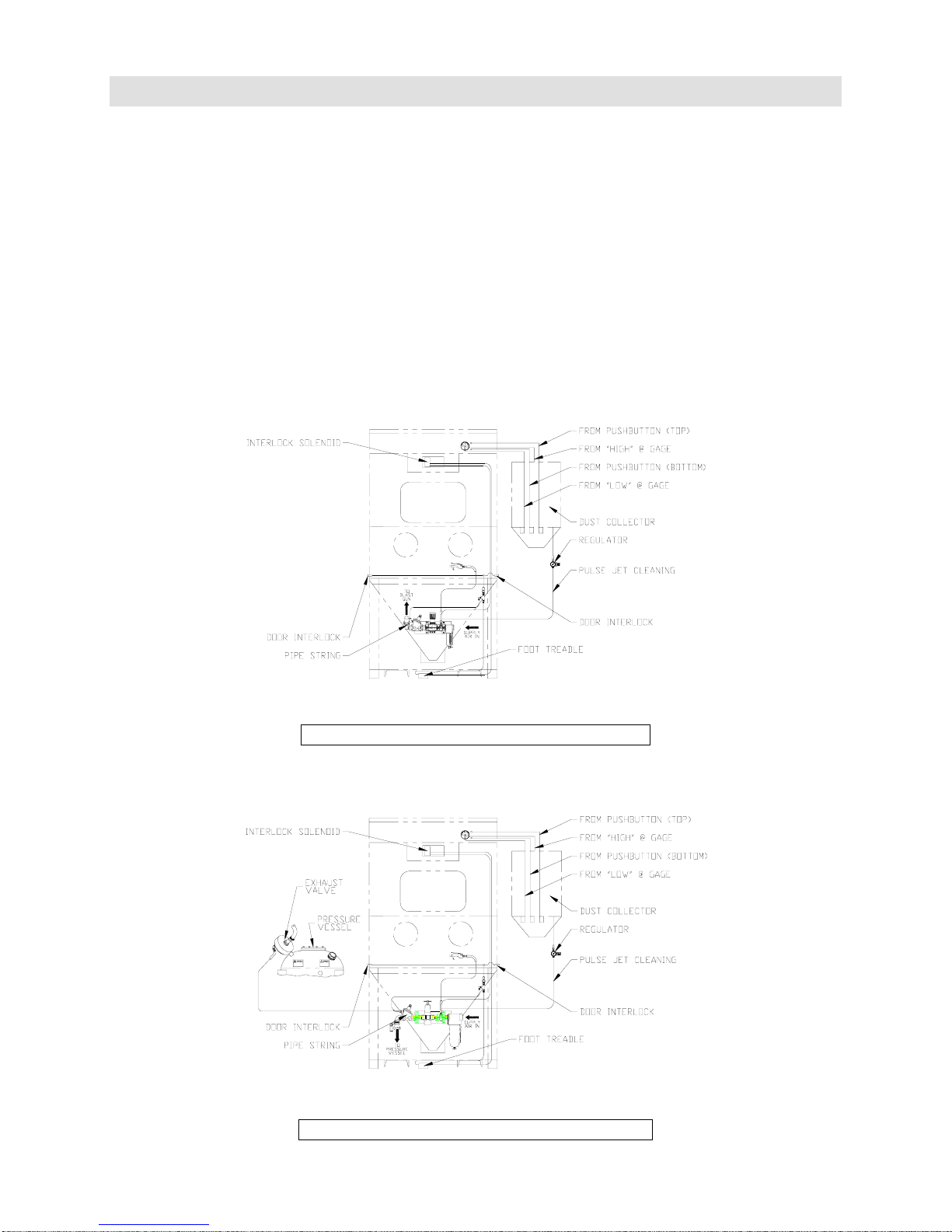
Refer to the control circuits shown in Figures 15 and 16 and the troubleshooting
procedures listed on the pages that follow.
Figure 15. Pneumatic Circuit – Suction
Figure 16. Pneumatic Circuit - Pressure
Page 35
Page 36
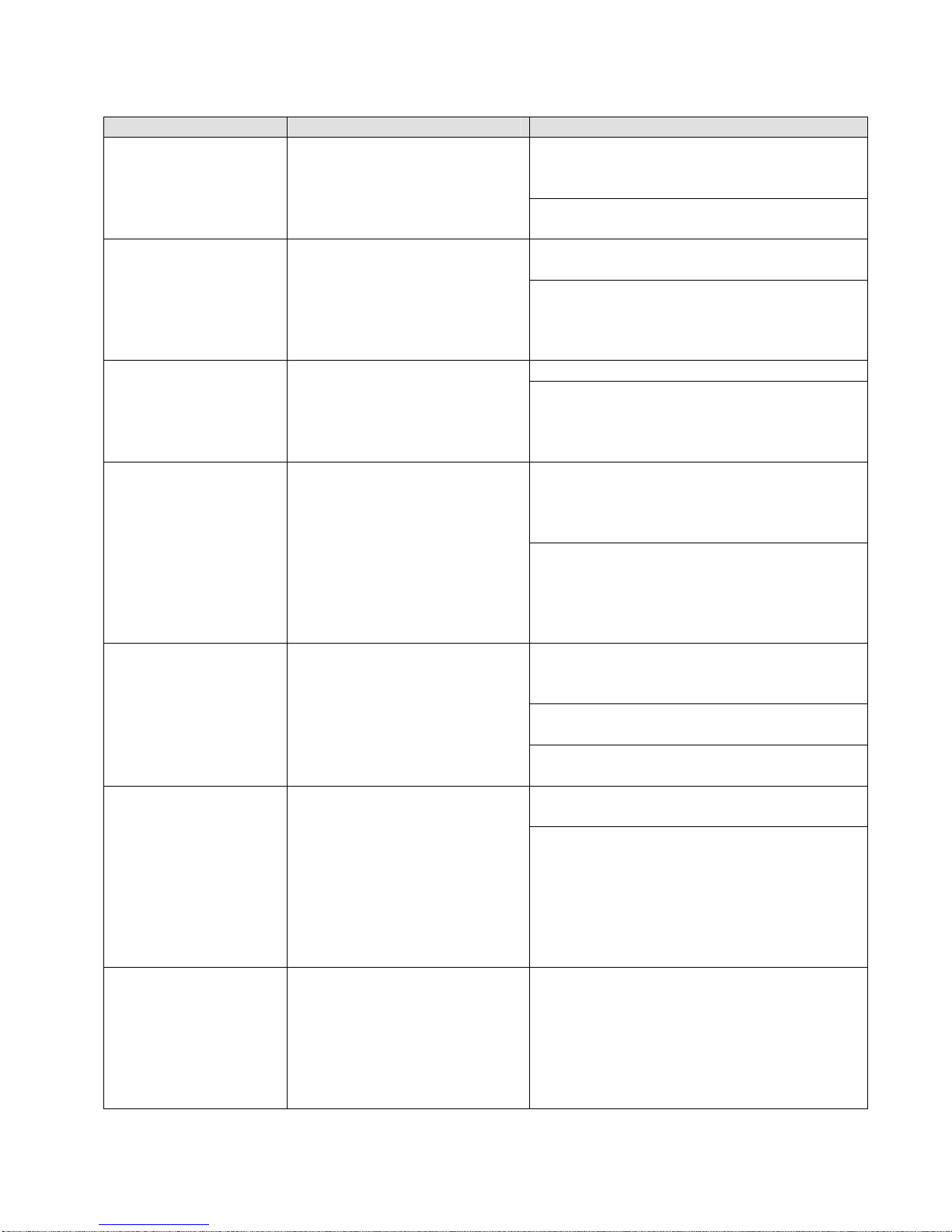
Empire Abrasive Equipment Company
Problem: Switch is on. The lights and dust collector motor work, but blast will not
activate.
Probable Cause Test Remedy
Step 1:
The compressed air
supply to the
system is off.
Confirm that the
compressed air is on by
activating the dust off gun
inside the blast cabinet.
If there is no air from the dust off
gun, turn the air supply to the system
on.
If there is air from the dust off gun, go
to Step 2.
Step 2:
The blast pressure
regulator is set to
zero.
Observe the blast pressure
gauge. If the gauge is at
zero, adjust the handle
clockwise until the
pressure is greater than
If there is no pressure, replace the
gauge and or regulator.
If the gauge shows that there is
pressure and still no blast, go to Step
3.
20 psi.
If there is no air, go to Step 4. Step 3:
If there is air, go to Step 5.
Failed interlock
solenoid or foot
treadle valve.
With the system on, open
a cabinet door and step on
the foot treadle. High
pressure air should exit
the door interlock air jet.
Step 4:
Failed foot treadle
valve.
Turn the snap switch off
and disconnect the air
supply hose on the left
side of the foot treadle.
Hold the loose hose end
away from personnel, and
switch the system on.
If no air exits the hose, the interlock
solenoid or snap switch is defective.
Replace the switch before replacing
the valve.
If air exits the hose, the foot treadle
valve has failed. Repair or replace the
valve.
High pressure air should
exit the hose.
Step 5:
The door air jets
are leaking.
With both cabinet doors
closed, step on the foot
treadle. Listen and feel for
air leaking at each door
interlock air jet.
If leaking, the cabinet access door
must be closed tightly so that the air
jets are sealed air tight.
Check and replace worn or damaged
urethane bumpers in the doors.
If the door interlock air jets are sealed
with no leaks, go to Step 6.
Step 6:
The control tubing
is leaking.
Disconnect the control
tubing at the pipe string
air valve. Install a
pressure gauge on the
If the gauge is reading the line
(supply) pressure, go to Step 7.
If the gauge reading is not the line
(supply) pressure, go to Step 8.
open end of the tubing
and step on the foot
treadle. The gauge should
indicate the line (supply)
pressure to the system.
Step 7:
The blast air valve
is defective.
Reconnect the control
tubing at the pipe string
air valve. Install a
pressure gauge on the
If the gauge is reading below the line
(supply) pressure, the blast air valve
diaphragm has failed. Repair or
replace the air valve.
control line and step on
the foot treadle. Observe
the gauge pressure.
Page 36
Page 37

Empire Abrasive Equipment Company
Check the vent in the
blast air valve diaphragm
cover spring retainer nut
Confirms that the blast air valve
diaphragm has failed. Repair or
replace the air valve.
for leaking air.
Step 8:
There are media
problems.
Improper media. See section 4.1 Media Selection and
Use.
Improper media flow. See section 3.0 Equipment
Adjustment.
Problem: There is excessive delay between stepping on the foot treadle and the blast
activation. Normally this delay should be between ½ and 1 second for suction systems
and 1 to 2 seconds for pressure systems.
Probable Cause Test Remedy
Step 1:
Restricted flow in
control lines.
Disconnect the control
tubing at the pipe string
air valve. Install a
Check for kinks or crimps in the
control air lines.
pressure gauge on the
open end of the tubing
and step on the foot
treadle. The gauge slowly
reaches the full line
(supply) pressure.
Step 2:
Leak in control
lines.
Disconnect the control
tubing at the pipe string
air valve. Install a
pressure gauge on the
open end of the tubing
and step on the foot
treadle. The gauge never
reaches the full line
Trace leaks by moving the gauge up
stream until the full line pressure is
observed.
For pressure systems only, if the
gauge at the exhaust valve
pressurizes rapidly to full line
pressure, the exhaust valve has a leak
or a ruptured diaphragm.
(supply) pressure.
Page 37
Page 38

Empire Abrasive Equipment Company
7.0 Recommended Spare Parts
The following chart lists the parts you should maintain in inventory to ensure
continuous operation of your ProFormer
Qty Part No. Description Pressure Suction
1
1
2 532701 Floodlights X X
20’ 524441 Door gasket X X
1 290182 Exhaust valve X
25’ 520792 ½” blast hose X
10 524802 5/8” blast hose X
10 520802
10 524101 QC washer X
1 518661 Foot treadle valve X X
2 pair 509891 Rubber gloves X X
1 524451 Window gasket X X
1 510401 Window safety glass X X
1 519001 Interlock solenoid X X
2 523523 Filter X X
1 523942 Sealing ring X
1 510431 Plunger, for 1 cu. ft. pressure vessel X
1
1 753551 MH-2 Gun Body X
2
6’ 520822 Exhaust hose X
2 520252 Tubing fittings X
1 523592 Sure-Flo metering tube ¾” X
501331
501341
501351
501272
501282
501292
522351
516103
505651
505661
505671
505691
¼” Di-carb nozzle (suction) or
5/16” Di-carb nozzle (suction) or
7/16” Di-carb nozzle (suction)
1/8” Di-carb nozzle (pressure) or
3/16” Di-carb nozzle (pressure) or
¼” Di-carb nozzle (pressure)
NW-5 nozzle washer for ceramic
nozzles
4 x 8 return hose or
6 x 3 Recovery hose
3/32” air jet or
1/8” air jet or
5/32” air jet or
7/32” air jet
™
system.
X
X
X
X X
X
Page 38
Page 39
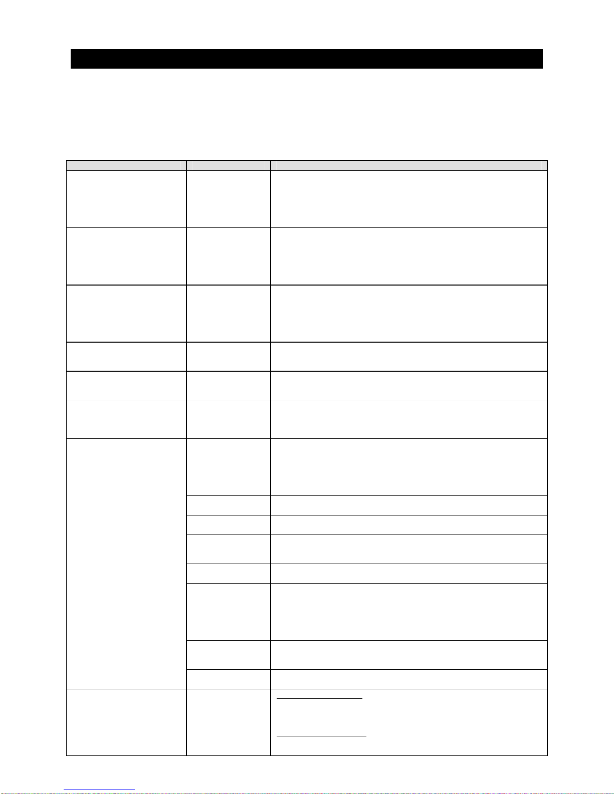
Empire Abrasive Equipment Company
8.0 Options and Accessories
A variety of standard accessories are
available for any ProFormer
™
system.
These accessories can be either factory
installed or customer installed with a
minimum of cabinet modification.
Category Options Description
1. Optional Electricals 220-240/50/1
2. Turntables - Stationary
or Tracks
3. Fine-Tuning Controls Pressure blast systems incorporating Empire’s automatic Sure-Flo
4. Fine-Tuning with Choke In applications where media is changed frequently, or where
5. Fixed-Orifice Media
Regulator
6. Low Media-Level Sensor
and Indicator (Factory
Installed Option)
7. Harsh Media and
Extended Wear
Components
8. Fixed Gun (or Nozzle)
Holder
208/60/3
220-240/60/3
380/50/3
440-480/60/3
550-600/60/3
Available with Manual, turntables facilitate the handling of heavy
In applications such as shot peening, in which very precise
The low media-level sensor and indicator warns the operator when
Empire’s extended wear components increase service life in an
Reclaimer
urethane coating
Reclaimer UltraWear lining
Di-Carb®
(tungsten carbide)
nozzles
Boron carbide
Nozzles
Rubber curtains Cabinet life is increased with the use of rubber curtains. Free-
Window
protectors
Matting To pad parts and prolong the life of steel support surfaces, mats
Suction blast systems
Voltage/Frequency/Phase of power available.
parts. The turntable dolly travels on a track, or is fixed inside the
cabinet. Most stationary designs feature a low profile that provides
operators with easy “over-the-top” access and does not waste
interior cabinet space. Turntable size 24” diameter with standard
capacities ranging from 300 to 1000 pounds.
media regulator, allow the operator to adjust the richness of the
air-to-media mixture from the workstation at the front of the
cabinet. As a result, dialing in the optimum air-to-media ratio for
a particular job is greatly simplified. To further assist the operator,
an indicator gauge displays relative media richness.
contamination can cause periodic clogging of the media regulator,
a push-button choke is available with fine tuning.
metering of media is required, a fixed-orifice media regulator is
attached below the Sure-Flo media regulator.
the media supply in the pressure vessel is low. The
indicator/sensor consists of an electronic probe in the vessel that
activates a signal light mounted on the front of the cabinet.
aggressive or high-use environment. These components are
normally very cost-effective because they reduce downtime, repair
interval, and maintenance costs. Extended wear components are
sold individually so you can tailor features to your application
needs and budget
The urethane coating extends the service life of interior wear
surfaces by five times.
The Ultra-Wear lining increases normal service life by a factor of
ten.
Di-Carb nozzles are for use with steel abrasives and glass beads.
Boron carbide nozzles are for use with aluminum oxide, silicon
carbide, and garnet media.
hanging curtains are made of black 1/8” neoprene and held in
place with rubber knobs for easy replacement. These curtains
actually last longer than steel. White curtains are available to
brighten the cabinet interior, and it doesn’t degrade with use, as
does white paint on steel.
Window protectors can be provided in clear plastic or as a
perforated screen to reduce frosting and pitting of the cabinet
window.
are offered for turntable tops and cabinet floors.
The fixed gun holder is adjustable to position any gun in any
orientation so the operator can use both hands to manipulate work
pieces in the blast stream.
Pressure blast systems
The fixed nozzle holder, which bolts anywhere on the cabinet wall,
can be adjusted to position the nozzle in any orientation, leaving
If your production requirements change,
you can add the options you need to
update your system.
Page 39
Page 40

Empire Abrasive Equipment Company
Category Options Description
9. Fine Media Kits Vibrating screen
10. Magnetic Reclaim
Separator
11. Dust Collector Option
NOTE: For more
information about
options, contact your
Empire distributor or
the factory.
and (for pressure
systems only)
aerated media
regulator
Magnetic reclaim separator reduces possible damage to delicate
Photohelic
Controlled pulse
jet cleaning
both of the operator’s hands free to manipulate work pieces.
A vibrating screen in the reclaimer (plus an aerated media
regulator for pressure systems) overcome flow problems associated
with very find abrasives (200 to 300 mesh range), lightweight blast
media (plastics, walnut shells, etc.), and high humidity.
substrates by removing steel and other ferrous contaminants from
the blast media as it passes through the reclaimer. The separator
consists of an industrial magnet that can be removed through the
reclaimer door for cleaning.
Automatically pulse the filters as required.
Page 40
Page 41
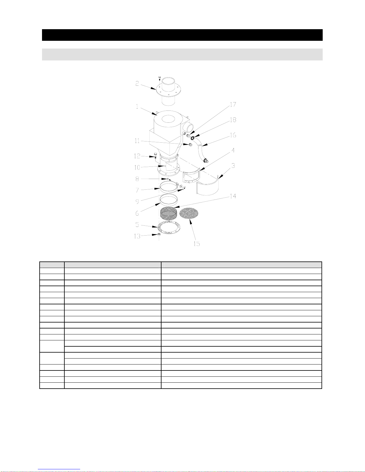
Empire Abrasive Equipment Company
9.0 ProFormerTM Parts
9.1 Reclaimer
Item 600 CFM Description
1 140796 Reclaimer Body Assembly
2 766741 Removable top
3 770788 Door, reclaimer
4 524321 Gasket, reclaimer door
5 524371 Gasket, reclaimer to storage hopper
6 524342 Gasket, tuning band
7 767581 Tuning Band (steel part only)
8 551782 Bolt, 1/4"-20 x 2"
9 552392 Wing nut, 1/4"-20
10 509581 Latch and keeper (requires welding)
11 544122 Plug, 1" NPT (Suction systems only)
12 551842 Bolt, 3/8"-16 x 1" (8 required)
13
14
15 760711 Screen, flat, 5/16", 13" OD
16 520822 Blast Hose, 1”, 5’ long
17 520181 Hose Barb, 1”
18 520512 Hose Clamp, 2”
552542 Nut, 3/8"-16 (1 gun suction systems), 8 required
522762 Lock Washer 3/8
739041 Screen, fine, 11-1/2" OD 8 Mesh
739051 Screen, coarse, 11-1/2" OD 4 Mesh
Page 41
Page 42
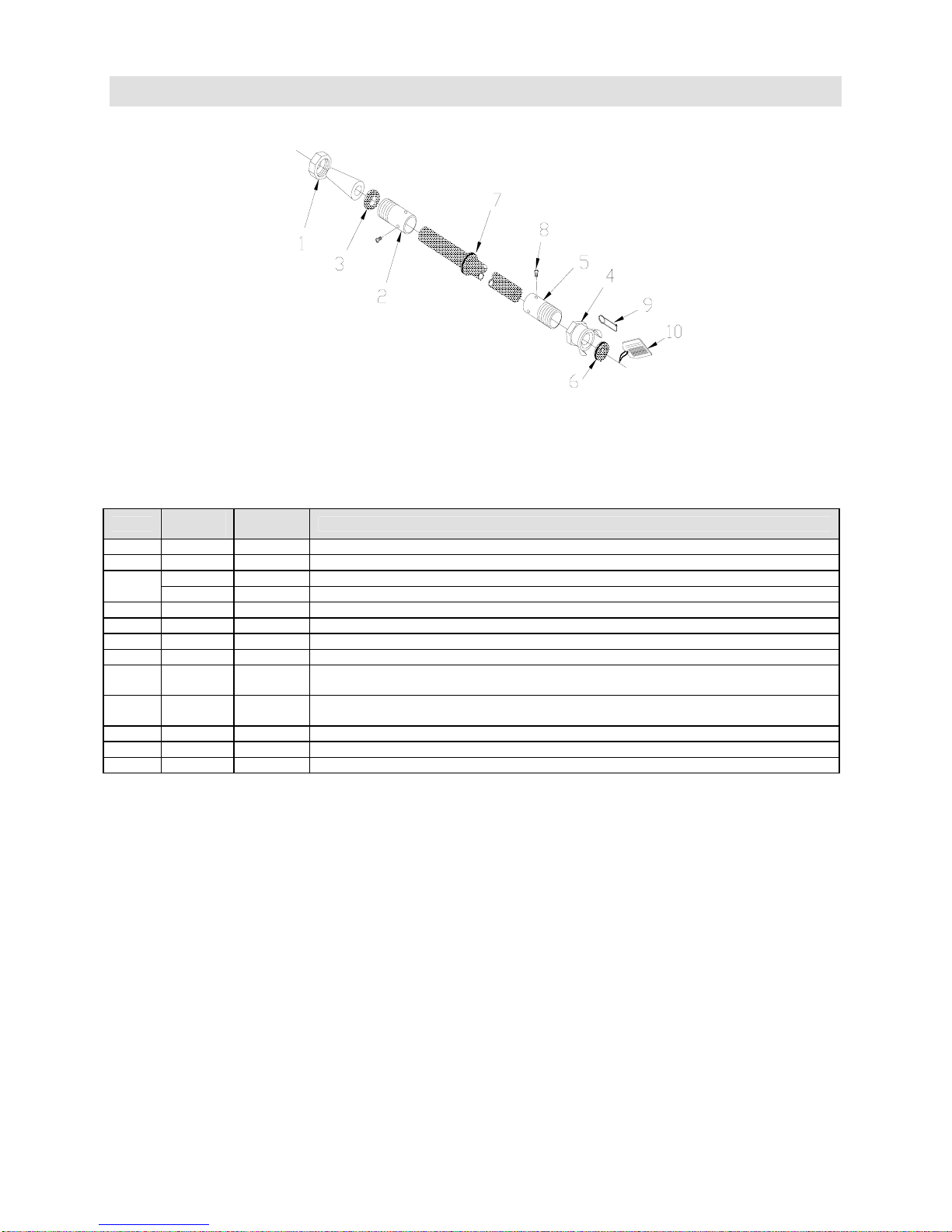
Empire Abrasive Equipment Company
9.2 Pressure Blast Systems
Parts for Blast Hose Assembly – Standard 1/2”
Item
1 504912 NA-2 Nozzle Adapter
2 505232 NC-1/2 Nozzle Coupling
3
4 505222 QC-1/2 Quick Coupling with washer + screw package item 4, 5, 6
5 505782 UF-100 Tank Coupling, 1" FPT with AHCW
6 524101 AHCW Coupling Washer (10 pack)
525102 AHCW Coupling Washer (25 pack)
7 523931
8 554242
9 510511 Safety pin
10 564822 Tag, safety, screw/coupling
11 520792 PBH-1/2 Blast Hose (Maximum length: 50')
Part
Number
524041 NW-5 Nozzle Washer, Ceramic nozzles, 5/8" ID (10 pack)
524052 NW-2 Nozzle Washer, Di-Carb/Boron, 1/2" ID (10 pack)
Model
Number
(1" x 13/8")
(#8 x
3/8")
Description
Grommet, blast hose
Screws (4 pack)
Page 42
Page 43
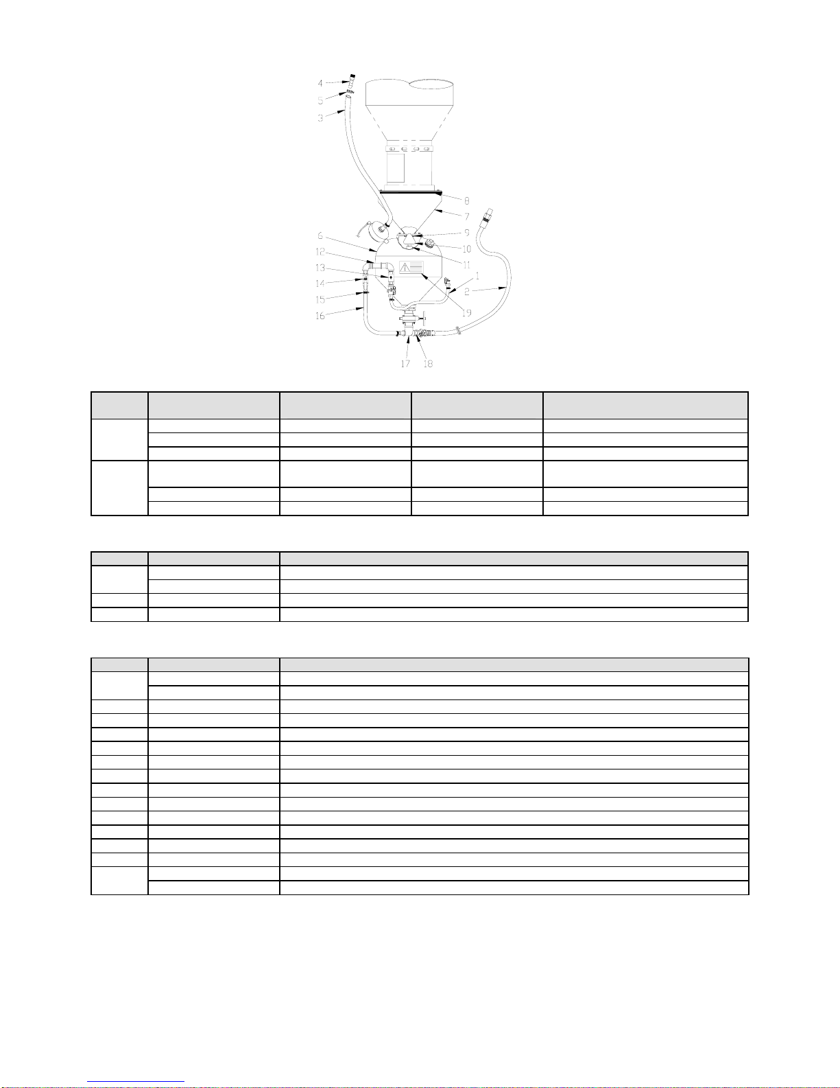
Empire Abrasive Equipment Company
Blast & Air Hoses
Item Bulk
1
2
— 140302 140303 Air hose assembly, 1" ID
520912 — — Air hose, 1" ID
(5') (6') (Air hose length)
— 522541 521672
520792 — — Blast hose, 1/2" ID
(5') (5') (Blast hose length, std cabinet)
3642
Only
4652
Only
Exhaust Hose
Item Part Number Description
3
4 520181 Hose barb, 1" NPT x 1" ID hose (1 each end)
5 520512 Hose clamp, 2" (1 each end)
522611 Exhaust hose assembly (with 1" NPT barb ends), 5’ for 1 cu. ft. vessel
520822 Exhaust hose (1" ID blast hose) (Maximum length: 50')
Pressure Vessel
Item Part Number Description
6
7 760739 Hopper, 1-cubic foot, ProFormer
8 524371 Gasket, reclaimer to hopper)
9 523942 Sealing ring, rubber, 2-1/8" ID
10 510431 Plunger, sealing, PVC coated
11 546072 Plunger guide (1/2" NPT x 3-1/2" nipple)
12 545702 Tee, 1" x 1” x 1/2" NPT
13 517503 Check valve, 1" NPT
14 518492 Ball valve, 1" NPT
15 520581 Hose clamp for 1" ID hose (1 each end)
16 520912 Hose, 1" ID (specify 1.5' for 1 cu. ft.; 3.5' for 3 cu. ft.)
17 545822 Tee, 1" x 2" x 1' NPT
18 546192 Nipple, 1" NPT x close, HD
19
140802 Pressure vessel assembly, 1 cu. ft.
760813 Pressure vessel only, 1 cu. ft., ProFormer
567332 Label, WARNING “Do not disassemble…”
567312 Label, WARNING “Flange above…”
Description
Blast hose assembly, 1/2" ID (see
previous chart)
Page 43
Page 44
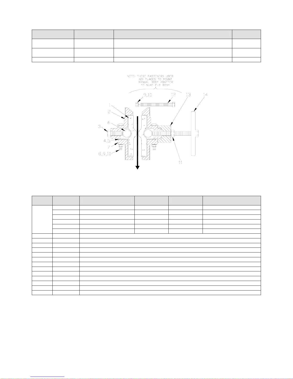
Empire Abrasive Equipment Company
Sure-Flo Media Regulators
Part Number Catalog Name Description
290383 Manual
290215 Automatic
290188 Conversion kit Converts Manual Sure-Flo to Automatic 25 lbs.
Manual Sure-Flo Media Regulator (grit valve)
normally open, 9" clearance required
Automatic Sure-Flo Media Regulator (grit valve)
normally closed, 9" clearance required
Shipping
Weight
25 lbs.
30 lbs.
Manual Sure-Flo Media Regulator Parts
Item
1
2 753692 Valve body, 2" MPT
3 552222 Bolt, 7/16"-14 x 1-1/4"
4 753092 Roller stop/holder
5 551352 Screw, 8-32 x 1/2" (2 per assembly)
6 753632 Pinch roller (2 per assembly)
7 753292 Flange, 2" MPT
8 552052 Bolt, carriage, 3/8"-16 x 2-1/2" (4)
9 552762 Lock washer, 3/8" ID (6)
10 552542 Nut, hex 3/8" -16 (6)
11 552672 1/2" Jam nut
12 551902 Bolt, hex 3/8" -16 x 3" (2)
13 753372 Adapter, manual body, Sure-Flo
14 290384 Handle assembly, 1/2" -13 x 4"
Part
Number
525451 Metering tube, 3/8" ID Small Fine Back out roller bolt 1/2"
525782 Metering tube, 1/2" ID Small-Med Fine-Med Back out roller 1/2"
523592 Metering tube, 3/4" ID Medium Medium Supplied as standard
523512 Metering tube, 3/4" ID Medium Medium Use below 32 F. (red)
525792 Metering tube, 5/8" ID Med-large Med-coarse —
525802 Metering tube, 7/8" ID Large Coarse High production use
Description Nozzle Grit Comments
Page 44
Page 45
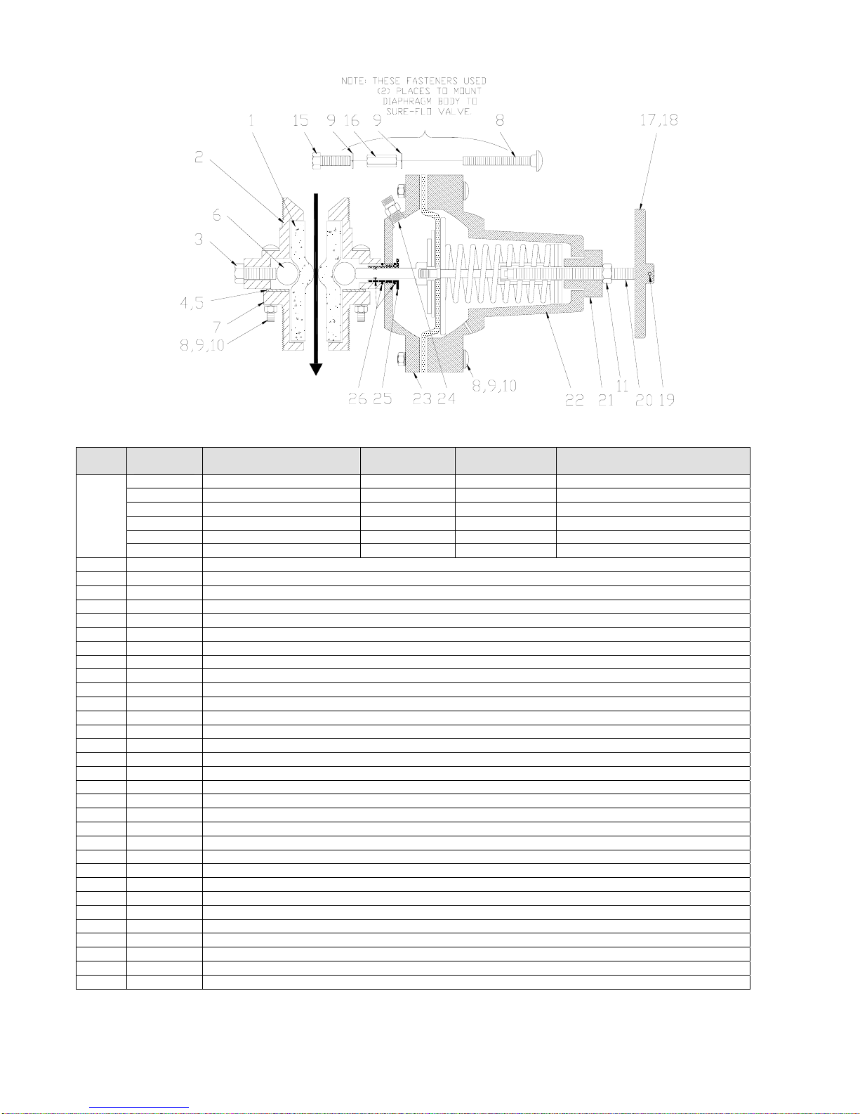
Empire Abrasive Equipment Company
Automatic Sure-Flo Media Regulator Parts
Item
1
2 753692 Valve body, 2" MPT
3 552222 Bolt, 7/16" - 14 x 1-1/4"
4 753092 Roller stop/holder
5 551352 Screw, 8-32 x 1/2" (2 per assembly)
6 753632 Pinch roller (2 per assembly)
7 753292 Flange, 2" MPT
8 552052 Bolt, carriage, 3/8"- 16 x 2-1/2" (10)
9 552762 Lock washer, 3/8" ID (12)
10 552542 Nut, hex 3/8" – 16 (8)
11 552672 1/2" Jam nut (1/2"-13)
12 N/A (Not shown in drawing)
13 N/A (Not shown in drawing)
14 N/A (Not shown in drawing)
15 551852 Bolt, 3/8" – 16 x 1-1/4" (2/Auto Sure-Flo)
16 552662 Nut, extension 3/8" – 16 (2/Auto Sure-Flo)
17 290217 Handle assembly, 1/2" – 13, Automatic Sure-Flo
18 753622 Handle (only), 1/2" – 13
19 551732 Set screw, 1/2" – 13 x 1/2", nyloc
20 505802 Shaft, handle
21 505822 Spring tensioner
22 753682 Spring enclosure
23 753112 Diaphragm cover
24 521081 Adapter, 1/4" NPT x 1/4" Tube)
25 753462 Plunger guide
26 561422 O-ring kit (includes 2 for guide & 1 for plunger)
27 505872 Plunger with O-ring
28 552842 Washer, 1/2" ID
29 525002 Gasket, diaphragm
30 525012 Diaphragm
31 290296 Spring assembly (includes item shown in Detail B)
32 565452 Tag, instructions, Sure-Flo
Part
Number
525451 Metering tube, 3/8" ID Small Fine Back out roller bolt 1/2"
525782 Metering tube, 1/2" ID Small-Med Fine-Med Back out roller bolt 1/2"
523592 Metering tube, 3/4" ID Medium Medium Supplied as standard
523512 Metering tube, 3/4" ID Medium Medium Use below 32 F. (red)
525792 Metering tube, 5/8" ID Med-large Med-coarse —
525802 Metering tube, 7/8" ID Large Coarse High production use
Description Nozzle Grit Comments
Page 45
Page 46
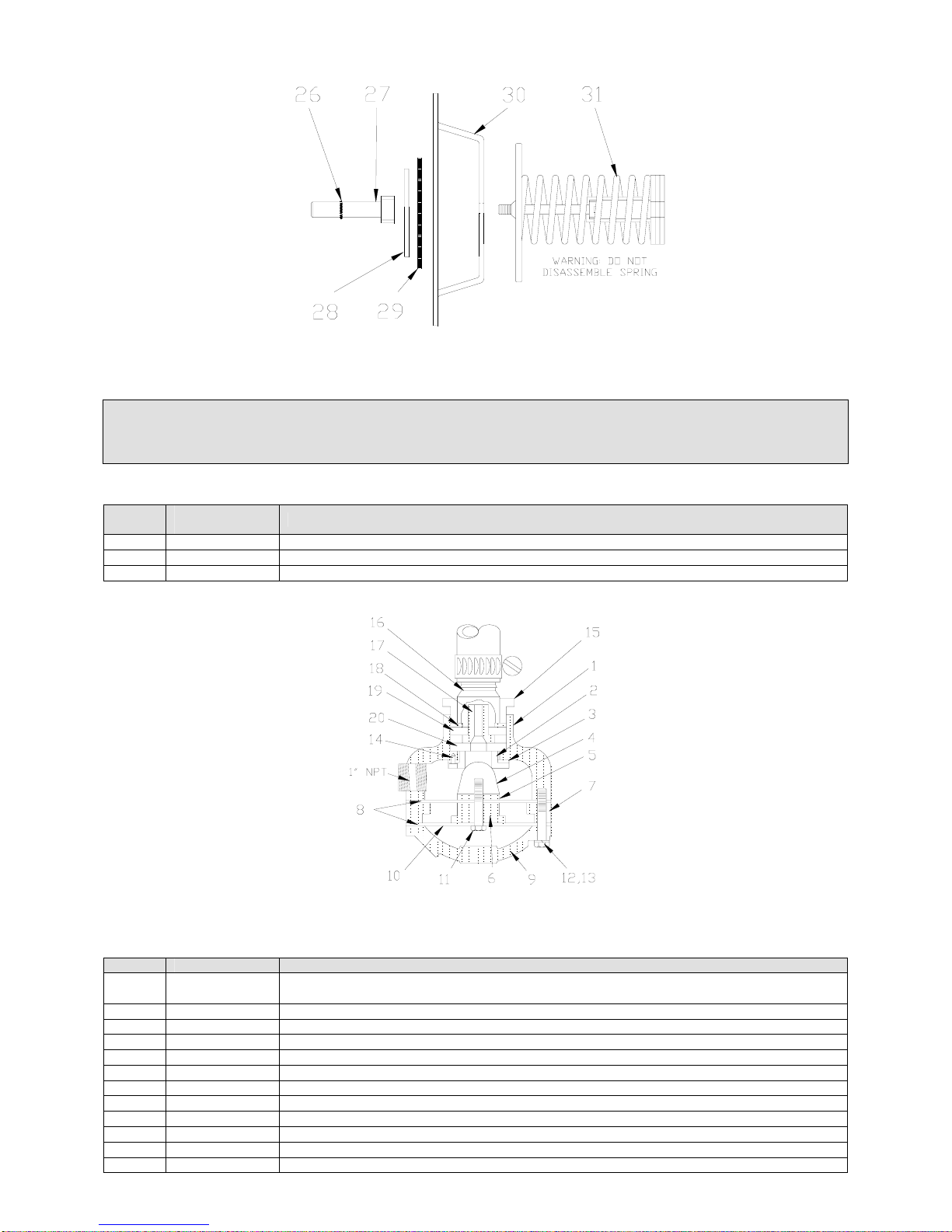
Empire Abrasive Equipment Company
Spring & Diaphragm Assembly Detail
WARNING
Never attempt to disassemble the spring assembly in the automatic Sure-Flo.
The spring is under tension and could cause injury to personnel.
MG-78 Exhaust Valve Assembly & Options
Item
290182 Exhaust valve, MG-78 (with ceramic restrictor kit)
290184 Boron carbide upgrade for restrictor kit, extended wear, Factory Installed (option)
502081 Boron carbide upgrade replacement restrictor.
Part
Number
Description
Exhaust Valve Components
Item Part Number Description
290183
1 753332 Valve body
2 753412 Seat, valve ball (steel)
3 524132 Gasket, seat
4 525322 Valve ball (also used on 411 & 412 valves)
5 553412 Spacer washer, steel (1/2" ID x 2" OD x 1/4" thick)
6 753392 Spacer ring, inner
7 753402 Spacer ring, outer
8 523672 Diaphragm (2 per assembly)
9 753382 Cover, valve
10 552842 Washer (1/2" ID x 2" OD x 1/16" thick)
11 551962 Bolt, 1/2" -13 x 1-3/4"
Rebuild Kit, MG-78 (Seat & gasket, ball, diaphragm, 3 screws, drawing). (items 2, 3, 4, 14)
Note: MG-78 castings must be in good condition to use PN 290183 effectively.
Page 46
Page 47

Empire Abrasive Equipment Company
12 553982 Bolt, 3/8" -16 x 2"
13 552762 Lock washer, 3/8"
14 551122 Screws, seat, 1/4" -20 x 1/2" (pack of 3)
15 544512 Reducer bushing, 1-1/4" MPT x 1" FPT
16 520181 Hose Barb 1”
Restrictor Parts
17
18 552952 Washer, steel
19 524062 Washer, nozzle, NW-1 (1" ID x 1-1/2" OD x 1/4" thick) (pack of 10)
20 524082 Washer, nozzle, NW-4 (3/4" ID x 1-1/2" OD x 1/4" thick) (pack of 10)
290218 Ceramic Restrictor kit (standard)
502431 Ceramic nozzle (standard)
502081 Boron carbide upgrade for restrictor kit, customer installed (extended wear)
290184 Boron carbide upgrade for restrictor kit, factory installed (extended wear)
Page 47
Page 48
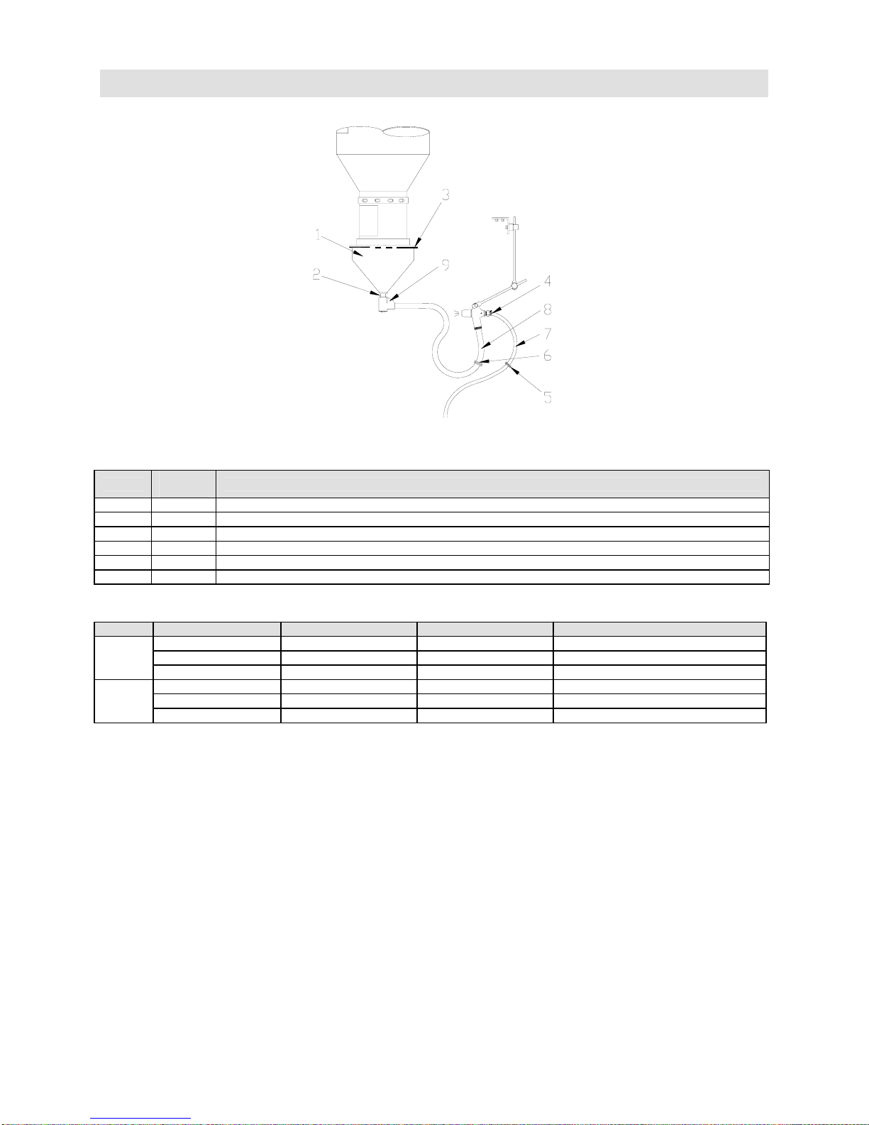
Empire Abrasive Equipment Company
9.3 Suction Blast Systems
Components
Item
1 760751 Hopper, 1 – gun suction
2 546332 Nipple, 1-1/4" NPT x 3"
3 524371 Gasket, reclaimer to hopper
4 520502 Hose clamp, 1/2" air hose (2 per hose)
5 523921 Grommet, air hose, 3/4" x 1-1/16"
6 523931 Grommet, blast hose, 1" x 1-3/8"
Blast & Air Hoses
Item Bulk 3642 4652 Description
7
8
Part
Number
— 522841 522851 Air hose assembly, 1/2" ID
520861 — — Air hose, 1/2" ID
(7') (8') (Air hose length, std cabinet)
— 522581 522591 Blast hose section, 5/8" ID
520802 — — Blast hose, 5/8" ID
(8') (9') (Blast hose length, std cabinet)
Description
Page 48
Page 49
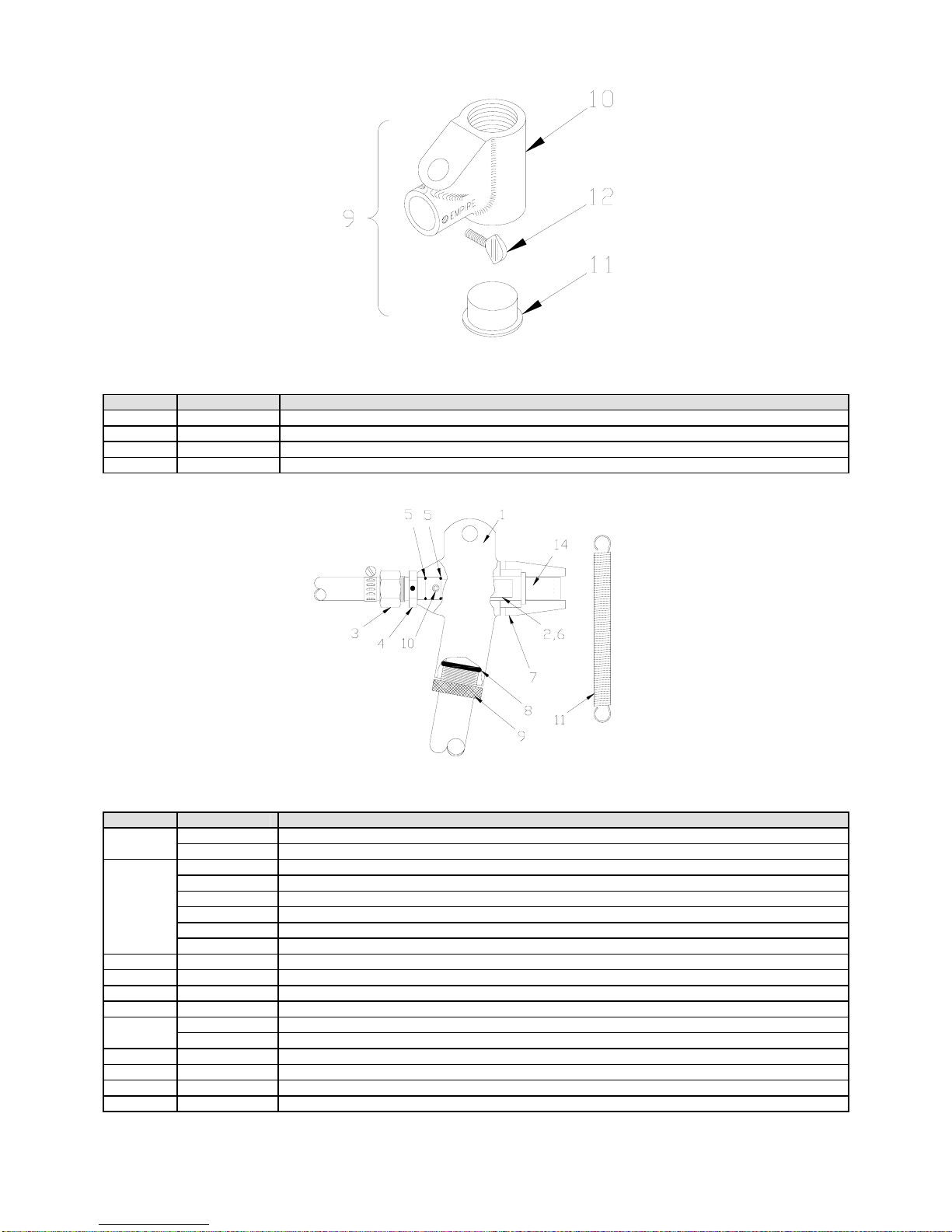
Empire Abrasive Equipment Company
SAR-2 Media Regulator
Item Part Number Description
9 290156 SAR-2 Media Regulator, complete, 1-1/4" FPT
10 753351 Regulator body, SAR-2
11 510121 Plug, clean out
12 551042 Thumb screw, 1/4"-20 x 1"
PARTS for MH-2 Guns
Item Part Number Description
1
2
3 520402 Hose barb, 1/2" FPT x 1/2" hose
4 505621 Connector, MH-2
5 523912 O-Ring, 1/2" ID x 5/8" OD (2 required)
6 526171 Sleeve, rubber, for air jet
7
8 523881 O-Ring, 1-1/16" ID x 1-5/16" OD
9 520081 Nut, hose clamp, MH-2
10 551702 Set screw, 1/4"-20 x 3/8"
11 511251 Spring, suction gun assist
753551 Gun body, MH-2 LONG handle
753561 Gun body, MH-2 SHORT handle
505651 Air jet, 3/32" (orange)
505661 Air jet, 1/8" (yellow)
505671 Air jet, 5/32" (green)
505681 Air jet, 3/16" (blue)
505691 Air jet, 7/32" (white)
505701 Air jet, 1/4" (red)
505641 Nozzle adapter, plastic (standard)
504931 Nozzle adapter, steel
Page 49
Page 50
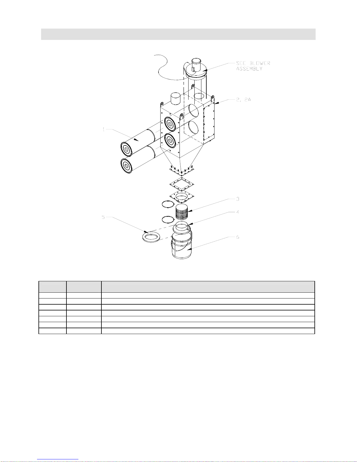
9.4 Dust Collector
Empire Abrasive Equipment Company
Components
Item
1 532523 Filter Assembly, (2)
2 516329 Diaphragm Valve, (2)
2A 516328 Rebuild Kit, Diaphragm Valve
3 516104 Hose, 7” ID x 6” long
4 516106 Cover
5 515710 Gasket, Neoprene, 9-1/2” ID x 12” OD
6 515765 Waste Pail
Part
Number
Description
Page 50
Page 51
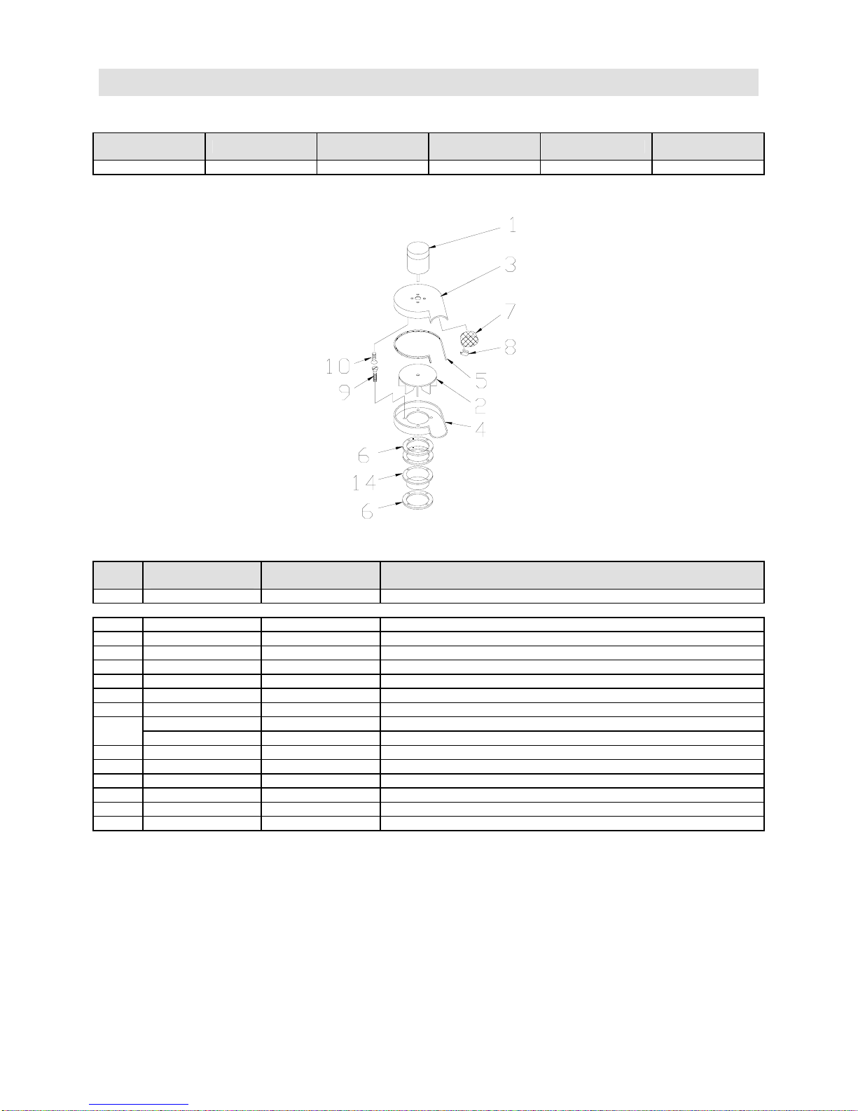
Empire Abrasive Equipment Company
9.5 Blowers (Fan & Motor)
Blower Assemblies
Part Number Horsepower
140312 1-1/2 230/60/1 600 SEM-2
Note: Motor starters, contactors, interconnecting wiring and ducting not included.
Standard
Electrical
CFM @
6" S.P.
Used with Notes
Components
Item
1 — 549681 Motor, 115/230V, 60 Hz, Single phase
(Motor part numbers shown in BOLD are supplied as standard most often.)
2 — 753661 Impeller (fan blade), 11-1/2" dia., 5/8" ID
3 — 753511 Housing, fan, top
4 — 753521 Housing, fan, bottom
5 523251 — Gasket, fan housing, 1/8" x 1/4" (5' section)
6 — 524361 Gasket, mounting (3 required)
7 — 739011 Guard, fan outlet
8 554431 — Clip, fan guard (4 required)
9
10 — 552072 Screw, flat head 3/8" -16 x 1
11 — — Bolt, 1/4" –20 x 3/4"
12 — — Clip, 1/4"-20
13 — — Bolt, 1/4"-20 x 1
14 — 751501 Flange
15 — 140759 Silencer (optional)
All
Sizes
— 553182 Screw, flat head 3/8" -16 x 2-1/4" (dust collector)
— 551312 Screw, flat head 3/8"-16 x 1-1/4" (slide gate)
1-1/2 Description
Page 51
Page 52
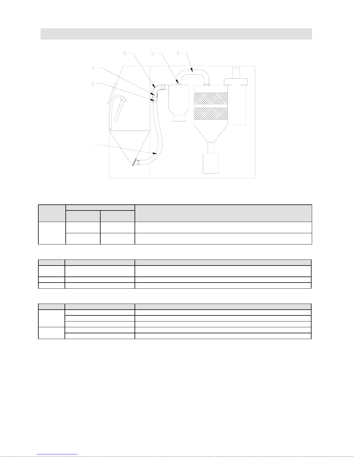
9.6 Ducting/Hoses
Empire Abrasive Equipment Company
Conveying Hose
Standard Systems – Suction or Pressure with Reclaimer & Collector
Item
1
Part Number
Customer
Installed
522351
(4" x 8’)
140354
(4" x 9’)
Factory
Upgrade
—
140338
4" x 9’
Description
Standard Duty Conveying Hose w/o clamps
(I.D. x length)
Heavy Duty Conveying Hose w/clamps
(I.D. x length)
Dust Hose
Item Part Number Description
2
3 526413 4” Urethane Elbow, 90 degrees
4 769917 Adapter, Ductwork, 4” Hose to 4” Urethane
516103
(6" x 31')
Standard Dust Hose, w/o clamps
(I.D. x length)
Clamps and Adapters
Item Part Number Description
5
6
Note: (2) hose clamps are required per hose.
520531 Hose clamp, Standard Duty conveying hose
522953 Hose clamp, Heavy Duty conveying hose
(4") (Nominal hose diameter)
520551 Hose clamp, dust hose
(6") (Nominal hose diameter)
Page 52
Page 53
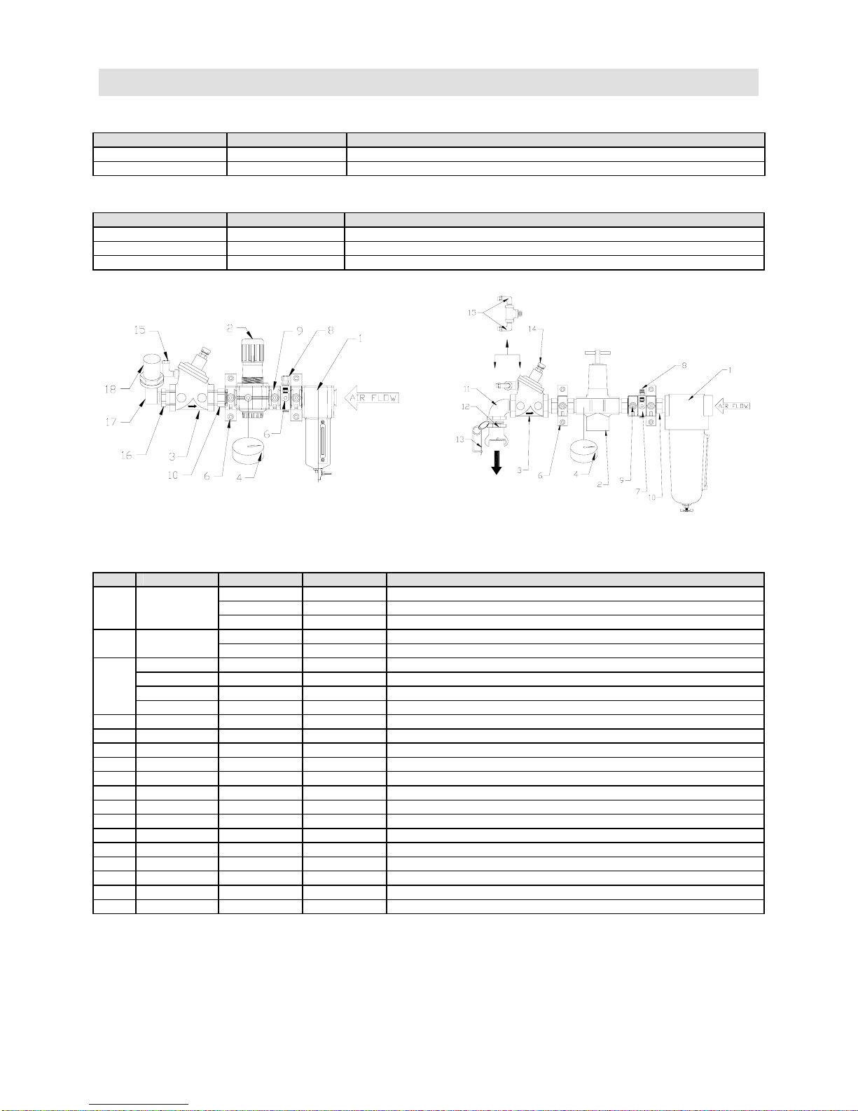
Empire Abrasive Equipment Company
9.7 Pipe Strings
Pipe String Assemblies
Part Number Pipe String Size Used With
140279 1/2" Suction – 1 gun
140280 1" Pressure, FaStrip
Pipe String Mounting Hardware
Part Number Quantity Description
564121 4 1/4" flat head bolt
552882 4 1/4" washer
552522 4 1/4" hex nut
1/2" Pipe String
1" Pipe String
Components
Item Both Sizes 1/2" Only 1" Only Description
1 —
2 —
517042 — — Main Air Valve (1" Aquamatic)
3
4 — 550232 550232 Gauge, (550232 1/4" NPT; 550212 1/8" NPT back mount)
6 522155 — — Mounting Feet/Quick Clamp
7 522157 — — Porting Block
8 520222 — — Hose adapter, 1/4" x 1/4"
9 522154 — — Quick Clamp
10 522156 — — Adapter
11 — — 543542 Elbow, 1" NPT street
12 — — 505782 Coupling, 1" FPT, UF-100
13 — — 510511 Safety pin
14 523261 — — Vent
15 520432 — — Adapter 1/4" Tube x 1/4" NPT 90
16 — 544497 — Bushing, 1" x 1/2" Brass
17 — 543533 — Elbow, 1/2" x 90
18 — 520362 — Hose Barb, 1/2"
* Repair kit P/N 517583 includes the seal kit P/N 517582.
O-Ring for modular pipe strings P/N 522162.
517582 — — Diaphragm and seal kit for 1" Aquamatic
518512 — — Special wrench for 1" Aquamatic
517583 — — Repair Kit for 1" Aquamatic*
504652 517271 Air Filter (1/2" manual, 1" manual; Norgren)
508012 508002 Element for Norgren air filter, 5µ
508112 505161 O-ring and gasket kit for Norgren air filter
517141 517251 Air Pressure Regulator (Norgren)
508102 508161 Diaphragm & O-ring kit for Norgren regulator
Page 53
Page 54
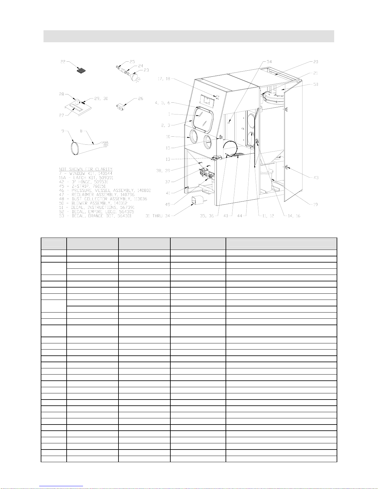
Empire Abrasive Equipment Company
9.8 Basic Cabinet Assembly
Components
Item
1* 510401 — — Safety Glass, 14" x 22" ∆
2† 524451 — — Gasket, window, 6' section
3
4 510461 — — Knob, 3/8" -16, (4) required
5 551852 — — Bolt, 3/8" -16 x 1-1/4", (4) required
6 525931 — — Spacer, window, (4) required
7 140544 — — Window Kit (items 1 through 6)
8*
9 520561 — — Clamp, 8", per glove
10 555016 — — Glove Hole Flange, Plastic
11 524441 — —
12† 525041 — — Bumper, urethane
13† 521561 — — Interlock Hose
14 509371 — — Latch, Door, w/o Handle Hole
15 751242 — — Catch, Door
16 509381 — — Spacer, Catch, Shim Only
16A 300016 — — Latch Kit, Items 14, 15 & 16
17 504201 — — Gauge, Minihelic
18 504101 — — Manual Pushbutton, (2) required
19 509611 — — Dust Bucket, 5 Gallon
20 — 765023 765043 Roof Cover
21 516103 — — Dust Hose, 6”
22 510491 — Filter, Kleensweep™ inlet, (2) required
23† 532701 — — Floodlight bulb
24* 580191 — — Gasket, light bulb, 1 per bulb
25 532711 — — Light fixture, with gasket
26† 534561 — — Switch, Snap, 20 amp
27 533611 — — Terminal strip, 10 pole
28† 519001 — — Solenoid valve, Standard and CSA
29† 520252 — — Barbed fitting, 1/4" tube x #10-32
30 520432 — — Adapter, 1/4" tube x 1/8" MPT, 90˚
Both
Sizes
760291 — — Frame, window
523551 — — Gasket, window frame per ft., 6’ required
509891 — — Gloves, pair
510821 — — Glove, left hand
3642
Only
4652
Only
Description
Gasket, ¾” x ¾”, 20” for 3642/24” for
4652
Page 54
Page 55
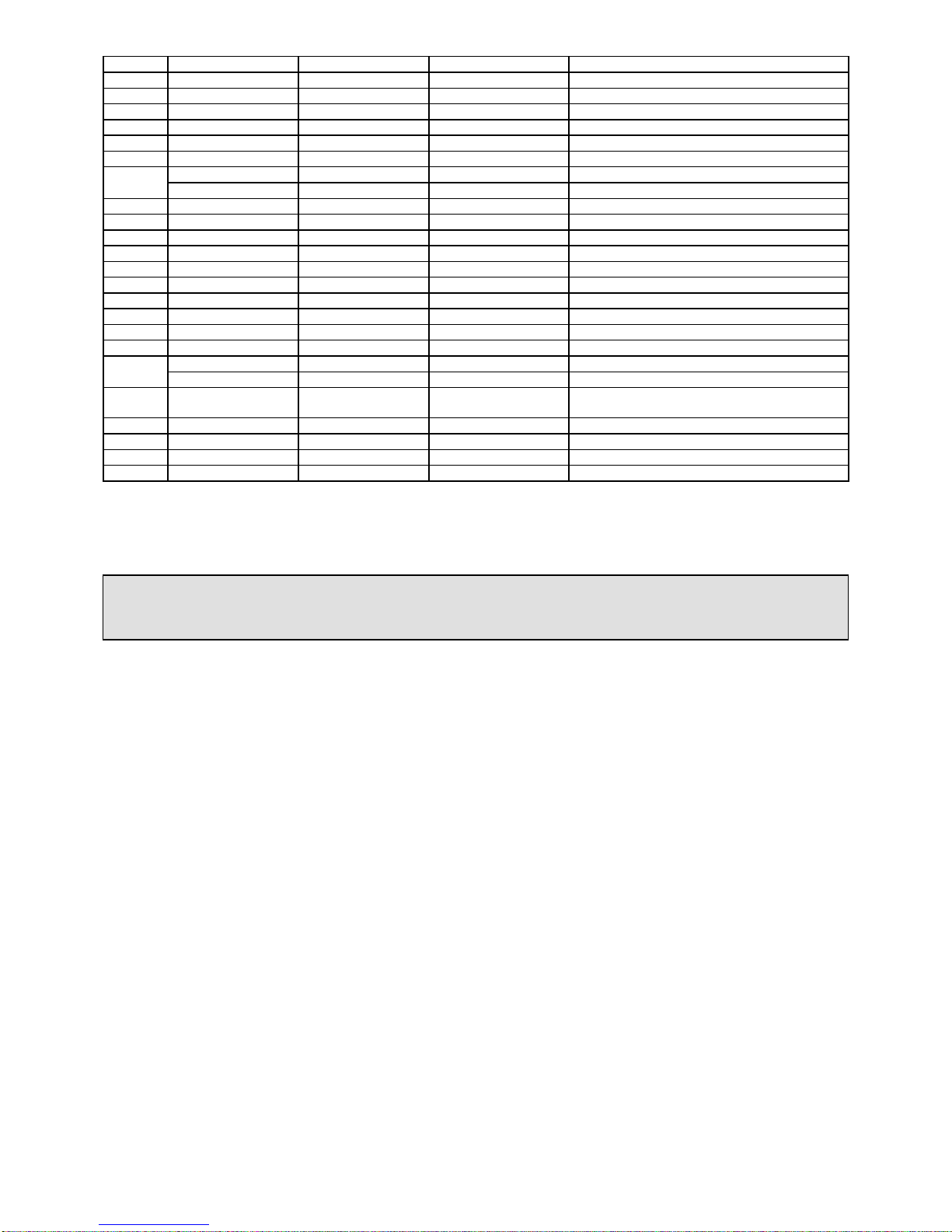
Empire Abrasive Equipment Company
31 518651 — — Foot Treadle Assembly
32† 518661 — — Valve, for Foot Treadle
33 518671 — — Repair Kit, For Treadle Valve
34 522661 — — Hose Assembly, ¼”, for Foot Treadle
35 509821 — — Gun, dust off
36 522631 522641 Hose with fittings, dust off gun
37 523951 — — Grommet, dust off hose 1/4"-5/8" x 7/8"
38
39 536391 Hole Seal
40 — 760697 760698 Floor section, std cabinet, (2) required
41 — 551742 551742 Leveling bolt, 3/8" -16 x 2", (4) required
42 509531 — — Hinge, 3", (10) required
43 509005 — — Latch, Compression, (4) required
44 523523 — — Filter, SEM-2, (2) required
45 760151 — — Z-strip, reclaimer mount
46 140802 — — Pressure Vessel Assembly,
47 140796 — — Reclaimer Assembly
48 113036 — — Dust Collector Assembly, SEM-2
49
50 140312 — —
51 567391 — — Decal, Instruction/Warnings
52 564305 — — Decal, Empire logo
53 564301 — — Decal, orange dot strip, 42” **
54 523533 — — Rubber nut, 1/4"-20 (for optional curtains)
* Recommended spare part – consumable wear item.
† Essential component - to prevent downtime.
†† For systems with optional equipment
** Specify length (per foot)
523931 — — Grommet, blast hose, 1"x 1-3/8"
523921 — — Grommet, suction air hose, 3/4" x 1-1/16"
140280 — — Piping Assembly, 1”
140279 — — Piping Assembly, ½”
Blower Assembly, 1-1/2 HP,
230V/60Hz/1-Ph
WARNING
Replace the window with Empire safety glass only. Failure to do so could result
in serious injury.
Page 55
Page 56

Empire Abrasive Equipment Company
10.0 Warranty
Empire Abrasive Equipment Company (“Empire”) warrants all parts and equipment
against defect in material and workmanship to the original purchaser for a period of
three (3) years
components that are determined by Empire to be defective will be repaired or replaced
at not additional charge.
LIMITATIONS:
1. This warranty does not apply to normal wear items such as nozzles, blast hose,
and reclaimers or to other components that are exposed to direct contact with blast
media.
2. The buyer must follow all recommended maintenance schedules; see Operating
Instruction on prior pages.
3. Does not apply to misapplication of product.
4. Unauthorized service, repair, improper installation, improper operation, improper
maintenance, alternations, misuse, neglect, accident or excessive ambient
conditions will void the warranty.
5. If genuine Empire replacement parts are not used the warranty is void.
6. Returned Material Authorization (RMA) form must be completed and accompany all
returned goods. Returns are not recognized without prior authorization and RMA
number.
7. Associated installation costs are excluded.
8. Freight costs for goods returned to Empire are to be assumed by the buyer unless
the parts are determined defective by Empire.
9. Parts that are not supplied by Empire are not covered. Commercial components
are warranted under term of the original manufacturer.
after shipment. Upon prompt notification by the buyer, to Empire,
Page 56
 Loading...