

Empire Mantis FG28BM-1, Mantis FG28BMN-1, Mantis FG28BMP-1, Mantis IG28BM-1, Mantis IG28BMN-1 Installation Instructions Manual
...Page 1
INSTALLATION INSTRUCTIONS
INSTALLER: Leave this manual with the appliance.
CONSUMER: Retain this manual for future reference.
™
WARNING: If not installed, operated and maintained in accordance with the manufacturer’s instructions, this product could expose you to substances in fuel or from fuel
combustion which can cause death or serious illness.
Attention: Check local codes for venting requirements.
WARNING
FIRE OR EXPLOSION HAZARD
Failure to follow safety warnings exactly
could result in serious injury, death or
property damage.
— Do not store or use gasoline or other am-
mable vapors and liquids in the vicinity of
this or any other appliance.
— WHAT TO DO IF YOU SMELL GAS
• Do not try to light any appliance.
• Do not touch any electrical switch; do
not use any phone in your building.
• Leave the building immediately.
• Immediately call your gas supplier
from a neighbor’s phone. Follow the
gas supplier’s instructions.
• If you cannot reach your gas supplier,
call the re department.
— Installation and service must be per-
formed by a qualied installer, service
agency or the gas supplier.
POWER-VENT
HIGH-EFFICIENCY FIREPLACE
MODELS
FG28BM(N,P)-1
IG28BM(N,P)-1
This appliance may be installed in an
aftermarket, permanently located,
manufactured home (USA only) or mobile
home, where not prohibited by state or local
codes.
This appliance is only for use with the type
of gas indicated on the rating plate. This
appliance is not convertible for use with other
gases, unless a certied kit is used.
WARNING
HOT GLASS
CAUSE BURNS.
DO NOT TOUCH
UNTIL COOLED.
NEVER
A barrier designed to reduce the risk of burns from the
hot viewing glass is provided with this appliance and shall
be installed for the protection of children and other at-risk
individuals.
ALLOW CHILDREN
TO TOUCH GLASS.
WILL
GLASS
Page 1
Page 2

TABLE OF CONTENTS
SECTION PAGE
Important Safety Information ............................................................................................................ 3
Safety Information for Users of LP-Gas............................................................................................ 4
Requirements for Massachusetts ..................................................................................................... 5
Introduction ....................................................................................................................................... 6
Specications and Accessories ........................................................................................................7
Installation and General Safety Information ..................................................................................... 8
Gas Supply ....................................................................................................................................... 9
Vent Clearances .............................................................................................................................10
Venting Requirements ...............................................................................................................11-12
Vent Adaptor Kits ............................................................................................................................ 12
PVVK-CFA Flex Vent Kit .................................................................................................................12
PVVTC Termination Cap Vent Kit ................................................................................................... 13
Vent Examples for Single Flue ..................................................................................................14-15
PVCA Horizontal Colinear Direct Vent Adaptor .............................................................................. 16
Colinear Transition Vent Kit ............................................................................................................ 17
Direct Vent and Colinear Vent Examples...................................................................................18-20
PVVK-24H and PVVK-48H Vent Kit ..........................................................................................21-23
Rough Framing Dimensions ........................................................................................................... 24
Insert Into Masonry Fireplace ......................................................................................................... 25
Clearance to Combustibles ............................................................................................................ 26
Specications ............................................................................................................................27-28
Gas Connection Installation............................................................................................................ 29
Lighting Instructions........................................................................................................................ 30
Wiring ............................................................................................................................................. 31
Start Up Check List......................................................................................................................... 31
Start Up and Adjustments ..........................................................................................................32-33
Remote Instructions...................................................................................................................34-40
Troubleshooting .............................................................................................................................. 41
Automatic Humidier Operation...................................................................................................... 42
Maintenance & Service..............................................................................................................42-43
Decorative Glass and Rock Media Accessory Installation.........................................................44-45
Parts List......................................................................................................................................... 46
Parts View ......................................................................................................................................47
Master Parts Distributor List ........................................................................................................... 48
How To Order Repair Parts ............................................................................................................ 48
Warranty Terms .............................................................................................................................. 49
Appliance Service History..........................................................................................................50-51
31792-4-1115Page 2
Page 3
IMPORTANT SAFETY INFORMATION
THIS IS A HEATING APPLIANCE
Safety markings are frequently used in this manual to designate a degree or level of
seriousness and should not be ignored.
WARNING indicates a potentially hazardous situation that if not avoided, could re-
sult in personal injury or death.
CAUTION indicates a potentially hazardous situation that if not avoided, may result
in minor or moderate injury or property damage.
WARNING
This appliance must be installed and repaired by a quali-
ed service person who is familiar with the proper installation and operation of the Mantis Power-Vent High Ef-
ciency Fireplace. Installers who are not familiar with the
installation of the Mantis and have questions, should contact Empire Comfort Systems, Inc. prior to installing the
appliance to avoid creating a hazardous operating condition.
• Due to high temperatures the appliance should be
located out of trafc and away from furniture and
draperies.
• Children and adults should be alerted to the hazards
of high surface temperatures and should stay away to
avoid burns or clothing ignition.
• Young children should be carefully supervised when
they are in the same room as the appliance. Toddlers,
young children and others may be susceptible to accidental contact burns. A physical barrier is recommended if there are at risk individuals in the house. To re-
strict access to a replace or stove, install an adjustable
safety gate to keep away toddlers, young children and
other at risk individuals out of the room and away from
hot surfaces.
• Clothing or other ammable material should not be
placed on or near the appliance.
• Any safety screen or guard removed for servicing an
appliance, must be replaced prior to operating the
appliance.
• Keep burner and control compartment clean.
• For manufactured home (USA only) or mobile home
or residential installation convertible for use with
natural gas and liqueed petroleum gases when
provision is made for the simple conversion from one
gas to the other.
• Young children should be carefully supervised when
they are in the same room as the appliance. Toddlers,
young children, and others may be susceptible to accidental contact burns. A physical barrier is recommended if there are at-risk individuals in the house. To
restrict access to a replace or stove, install an adjustable safety gate to keep toddlers young children, and
other at-risk individuals out of the room and away from
hot surfaces.
• A barrier designed to reduce the risk of burns from the
hot viewing glass is provided with this appliance and
shall be installed for the protection of children and other
at-risk individuals.
• If the barrier becomes damaged, the barrier shall be
replaced with the manufacturer’s barrier for this appliance.
• Any safety screen, guard, or barrier removed for servicing an appliance must be replaced prior to operating the
appliance.
WARNING
Installation and repair should be done by a QUALIFIED
SERVICE PERSON. The appliance should be inspected be-
fore use and at least annually by a qualied service person.
More frequent cleaning may be required due to excessive
lint from carpeting, bedding materials, etc. It is imperative
that control compartments, burners and circulating air passageways of the appliance be kept clean.
• DO NOT put anything around the replace that will
obstruct the ow of combustion and ventilation air.
• DO keep the appliance area clear and free from
combustible material, gasoline and other ammable
vapors and liquids.
• Do examine venting system periodically and replace
damaged parts.
• Do make a periodic visual check of burner. Clean and
replace damaged parts.
• DO NOT use this replace if any part has been under
water. Immediately call a qualied service technician to
inspect the replace and to replace any part of the con-
trol system and any gas control which has been under
water.
• DO NOT operate this appliance without the front panel
installed.
Note to the Installer
1. The installer must leave instruction manual with owner after
installation.
2. The installer must have the owner ll out and mail
registration card supplied with the replace.
3. The installer should show the owner how to start and
operate replace and thermostat.
4. The installer must locate replace near a grounded wall
receptacle for 115VAC power and must provide gas supply
and vent the replace properly for safe operation.
31792-4-1115 Page 3
Page 4

SAFETY INFORMATION FOR USERS OF LP-GAS
LP-Gas (Propane) is a ammable gas which can cause res and
explosions. In its natural state, propane is odorless and colorless.
You may not know all the following safety precautions which can
protect both you and your family from an accident. Read them
carefully now, then review them point by point with the members
of your household. Someday, there may not be a minute to lose,
everyone’s safety will depend on knowing exactly what to do. If,
after reading the following information, you feel you still need
more information, please contact your gas supplier.
LP-GAS WARNING ODOR
If a gas leak happens, you should be able to smell the gas because of the odorant put in the LP-Gas.
That’s your signal to go into immediate action!
• Do not operate electric switches, light matches, use your
phone. Do not do anything that could ignite the gas.
• Get everyone out of the building, vehicle, trailer, or area. Do
that IMMEDIATELY.
• Close all gas tank or cylinder supply valves.
• LP-Gas is heavier than air and may settle in low areas such
as basements. When you have reason to suspect a gas leak,
keep out of basements and other low areas. Stay out until
reghters declare them to be safe.
• Use your neighbor’s phone and call a trained LP-Gas service
person and the re department. Even though you may not
continue to smell gas, do not turn on the gas again. Do not
re-enter the building, vehicle, trailer, or area.
• Finally, let the service man and reghters check for escaped
gas. Have them air out the area before you return. Properly
trained LP-Gas service people should repair the leak, then
check and relight the gas appliance for you.
NO ODOR DETECTED - ODOR FADE
Some people cannot smell well. Some people cannot smell the
odor of the chemical put into the gas. You must nd out if you
can smell the odorant in propane. Smoking can decrease your
ability to smell. Being around an odor for a time can affect your
sensitivity or ability to detect that odor. Sometimes other odors in
the area mask the gas odor. People may not smell the gas odor
or their minds are on something else. Thinking about smelling a
gas odor can make it easier to smell.
The odorant in LP-gas is colorless, and it can fade under some
circumstances. For example, if there is an underground leak, the
movement of the gas through soil can lter the odorant. Odorants
in LP-Gas also are subject to oxidation. This fading can occur if
there is rust inside the storage tank or in iron gas pipes.
The odorant in escaped gas can adsorb or absorb onto or into
walls, masonry and other materials and fabrics in a room. That
will take some of the odorant out of the gas, reducing its odor
intensity.
LP-Gas may stratify in a closed area, and the odor intensity
could vary at different levels. Since it is heavier than air, there
may be more odor at lower levels. Always be sensitive to the
slightest gas odor. If you detect any odor, treat it as a serious leak.
Immediately go into action as instructed earlier.
• Learn to recognize the odor of LP-gas. Your local LP-Gas
Dealer can give you a “Scratch and Sniff” pamphlet. Use it
to nd out what the propane odor smells like. If you suspect
that your LP-Gas has a weak or abnormal odor, call your
LP-Gas Dealer.
• If you are not qualied, do not light pilot lights, perform
service, or make adjustments to appliances on the LP-Gas
system. If you are qualied, consciously think about the odor
of LP-Gas prior to and while lighting pilot lights or performing
service or making adjustments.
• Sometimes a basement or a closed-up house has a musty
smell that can cover up the LP-Gas odor. Do not try to light
pilot lights, perform service, or make adjustments in an area
where the conditions are such that you may not detect the
odor if there has been a leak of LP-Gas.
• Odor fade, due to oxidation by rust or adsorption on walls
of new cylinders and tanks, is possible. Therefore, people
should be particularly alert and careful when new tanks or
cylinders are placed in service. Odor fade can occur in new
tanks, or reinstalled old tanks, if they are lled and allowed
to set too long before relling. Cylinders and tanks which
have been out of service for a time may develop internal
rust which will cause odor fade. If such conditions are sus-
SOME POINTS TO REMEMBER
pected to exist, a periodic sniff test of the gas is advisable. If
you have any question about the gas odor, call your LP-gas
dealer. A periodic sniff test of the LP-gas is a good safety
measure under any condition.
• If, at any time, you do not smell the LP-Gas odorant and
you think you should, assume you have a leak. Then take
the same immediate action recommended above for the
occasion when you do detect the odorized LP-Gas.
• If you experience a complete “gas out,” (the container
is under no vapor pressure), turn the tank valve off
immediately. If the container valve is left on, the container
may draw in some air through openings such as pilot light
orices. If this occurs, some new internal rusting could
occur. If the valve is left open, then treat the container as
a new tank. Always be sure your container is under vapor
pressure by turning it off at the container before it goes
completely empty or having it relled before it is
completely empty.
31792-4-1115Page 4
Page 5

REQUIREMENTS FOR MASSACHUSETTS
For all side wall horizontally vented gas fueled equipment installed
in every dwelling, building or structure used in whole or in part for
residential purposes, including those owned or operated by the
Commonwealth and where the side wall exhaust vent termination
is less than seven (7) feet above nished grade in the area of
the venting, including but not limited to decks and porches, the
following requirements shall be satised:
1. INSTALLATION OF CARBON MONOXIDE DETECTORS.
At the time of installation of the side wall horizontal vented
gas fueled equipment, the installing plumber or gastter shall
observe that a hard wired carbon monoxide detector with an
alarm and battery back-up is installed on the oor level where
the gas equipment is to be installed. In addition, the installing
plumber or gastter shall observe that a battery operated
or hard wired carbon monoxide detector with an alarm is
installed on each additional level of the dwelling, building or
structure served by the side wall horizontal vented gas fueled
equipment. It shall be the responsibility of the property owner
to secure the services of qualied licensed professionals for
the installation of hard wired carbon monoxide detectors
a. In the event that the side wall horizontally vented gas
fueled equipment is installed in a crawl space or an attic,
the hard wired carbon monoxide detector with alarm and
battery back-up may be installed on the next adjacent
oor level.
b. In the event that the requirements of this subdivision
can not be met at the time of completion of installation,
the owner shall have a period of thirty days to comply
with the above requirements; provided, however, that
during said thirty day period, a battery operated carbon
monoxide detector with an alarm shall be installed.
2. APPROVED CARBON MONOXIDE DETECTORS. Each
carbon monoxide detector as required in accordance with the
above provisions shall comply with NFPA 720 and be ANSI/
UL 2034 listed and IAS certied.
3. SIGNAGE. A metal or plastic identication plate shall be
permanently mounted to the exterior of the building at a
minimum height of eight feet above grade directly in line
with the exhaust vent terminal for the horizontally vented
gas fueled heating appliance or equipment. The sign shall
read, in print size no less than one-half (1/2) inch in size,
“GAS VENT DIRECTLY BELOW. KEEP CLEAR OF ALL
OBSTRUCTIONS”.
4. INSPECTION. The state or local gas inspector of the side
wall horizontally vented gas fueled equipment shall not
approve the installation unless, upon inspection, the inspector
observes carbon monoxide detectors and signage installed
in accordance with the provisions of 248 CMR 5.08(2)(a) 1
through 4.
(b) EXEMPTIONS: The following equipment is exempt from
248 CMR 5.08(2)(a)1 through 4:
1. The equipment listed in Chapter 10 entitled
“Equipment Not Required To Be Vented” in the most
current edition of NFPA 54 as adopted by the Board;
and
2. Product Approved side wall horizontally vented gas
fueled equipment installed in a room or structure
separate from the dwelling, building or structure
used in whole or in part for residential purposes.
(d) MANUFACTURER REQUIREMENTS - GAS
EQUIPMENT VENTING SYSTEM NOT PROVIDED.
When the manufacturer of a Product Approved side
wall horizontally vented gas fueled equipment does not
provide the parts for venting the ue gases, but identies
“special venting systems”, the following requirements
shall be satised by the manufacturer:
1. The referenced “special venting system” instructions
shall be included with the appliance or equipment
installation instructions; and
2. The “special venting systems” shall be Product
Approved by the Board, and the instructions for
that system shall include a parts list and detailed
installation instruction.
(e) A copy of all installation instructions for all Product
Approved side wall horizontally vented gas fueled
equipment, all venting instructions, all parts lists for
venting instructions, and/or all venting design instructions
shall remain with the appliance or equipment at the
completion of the installation.
31792-4-1115 Page 5
State of Massachusetts: The installation must be made
by a licensed plumber or gas tter in the Commonwealth of
Massachusetts.
Page 6

INTRODUCTION
WARNING
The safety information listed below must be followed
during the installation, service, and operation of this
product. Failure to following the safety recommendations
could result in possible damage to the equipment, serious
personal injury, or death.
Additional code information listed below is for reference purposes only and does not necessarily have jurisdiction over
local or state codes. Always consult with local authorities before installing any gas appliance.
Combustion and Ventilation Air
U.S.: National Fuel Gas Code NFPA 54/ANSI Z223.1(NFGC), Air
for Combustion and Ventilation.
Electrical Connections
U.S.: National Electrical Code (NEC) ANSI/NFPA 70
Gas Piping and Gas Pipe Pressure Testing
U.S.: NFGC and National Plumbing Codes
General Installations
U.S.: Current edition of the NFGC and NFPA 90B. For copies contact the National Fire Protection Association Inc., Batterymarch
Park, Quincy, MA 02269 or American Gas Association, 400 N.
Capitol, N.W., Washington DC 20001 or www.NFPA.org.
Safety
U.S.: NFGC NFPA 5/ANSI Z223.1
31792-4-1115Page 6
Page 7
SPECIFICATIONS & ACCESSORIES
SPECIFICATIONS
Models (F,I)G28BM(N,P)
Maximum Input BTU/HR (KW/H) 20,000 (5.86)
Minimum Input BTU/HR (KW/H) 10,000 (2.93)
Height 24-9/16”
Width 28”
Depth 17-3/16”
Gas Inlet (Pipe) 3/8” Flair
Electrical - The replace comes equipped with a 5 foot (1.5 m) 3 pronged cord, for connection to an approved 115 VAC, 60 Hz, 5A
(maximum) wall receptacle.
Vent Pipe: - 1-1/2 inch diameter schedule 40 PVC pipe, 40 feet maximum equivalent length with (3) 90° elbows.
ACCESSORIES
Venting
Part Number Description
PVVK-FC Single Flue Horizontal Vent Kit
PVCA Colinear Adapter
PVCT Colinear Transition Kit
PVVK-CFA Flex Vent Kit
PVVK-SV Single Flue Vertical Vent Kit
PVVTC Vertical Termination Cap - 1-1/2”
PVVK24H Coaxial Horizontal Direct Vent Kit (24”)
PVVK48H Coaxial Horizontal Direct Vent Kit (48”)
Surrounds with Barriers
Part Number Description
FWKQ28BL
FHKQ28BL In-Wall Surround Kit, Louverless with Barrier
FIKQ28BL
FFKQ28BL
Note: A barrier is required for operation of the appliance,
In-Wall Surround Kit, Picture Frame with
Barrier
38” Wide X 30-7/8” Tall Insert Surround Kit
with Barrier
35” Wide X 29-3/8” Tall Fireplace Mantel
Surround Kit with Barrier
Decorative Glass Kits (One kit per one square foot)
Part Number Description
DG1BKP Decorative Glass, Black Polished
DG1BUC Decorative Glass, Blue Clear
DG1CLF Decorative Glass, Clear Frosted
DG1AB
DG1GC
DG1 SL
DG1NXS
DG1RYC
DG1TZ
Part Number Description
DRFPA
Note: The total burner cover area is two square feet.
Note: Never place media material on or next to the burner. See
pages 44-45.
Decorative Glass Droplets 1/2” Aqua Blue
Decorative Glass Droplets 1/2” Glacier Ice
Decorative Glass Droplets - 1/2” Sangria
Luster
Decorative Glass Droplets 1” Onyx Solid
Decorative Glass Droplets 1” Ruby Clear
Decorative Glass Droplets 1” Topaz Clear
Decorative Rock Kits
Decorative Rock - Small (One kit per 1/2
square foot)
31792-4-1115 Page 7
Page 8

INSTALLATION AND GENERAL SAFETY INFORMATION
General Information
This series is designed certied in accordance with American National Standard/CSA Standard Z21.88 as a Gas Fireplace to be
installed according to these instructions.
Any alteration of the original design, installed other than as
shown in these instructions will be the responsibility of the
person and company making the changes, and will void the
warranty. This product may not be used with any type of gas
other than what is shown on the rating plate.
Important
All Correspondence should refer to complete Model Number,
Serial Number and type of gas.
Installation
Installation, replacement, gas piping, gas utilization equipment or
accessories, and the repair and service of this equipment must
be performed by a qualied agency. The term “qualied agency”
means any individual, rm, corporation or company which either in
person or through a representative is engaged in and is responsible for (a) the installation or replacement of gas piping or (b) the
connection, installation, repair or servicing of equipment, who is
experienced in such work, familiar with all precautions required
and has complied with all the requirements of the authority having
jurisdiction.
• This installation must conform with local codes, or in the
absence of local codes, the National Fuel Gas Code,
NFPA 54/ANSI Z223.1.
• This appliance, when installed, must be electrically grounded
in accordance with local codes or. In the absence of local
codes, with the National Electrical Code, ANSI/NFPA 70.
• Provide adequate clearances around the replace for servic-
ing and ensure there are no obstructions to the combustion air
intake situated at the back of the replace. Refer to Pages 24
to 28.
• The Mantis Power-Vent High-Efciency Fireplace must be installed on a at, solid continuous surface (i.e. wood, metal,
concrete). Rough or uneven surfaces can cause vibration or
humming in the replace.
• This appliance does need to be installed in such a way where
the replace can be removed for servicing the heat exchanger
and the ue that are located in the rear section of the re-
place.
• This appliance is equipped with a three-prong [grounding]
plug for your protection against shock hazard and should
be plugged directly into a properly grounded three-prong
receptacle. Do not cut or remove the grounding prong
from this plug. For an ungrounded receptacle, purchase an
adapter with two prongs and a wire for grounding.
Note: Under no circumstances should the appliance be installed
under conditions that would not allow for easy removal of
the appliance to carry out routine inspection and service
to the appliance.
Note: Where a mantel surround is being used on insert installa-
tions and zero clearance replace installations, the combustion air intake slot located in the top mantel surround
must not be obstructed. This will allow combustion air to
enter through the slot to the combustion air inlet located
at the back of the replace.
Note: During initial ring of this replace, residual oil from the
heat exchanger may bake off and smoke may occur.
Provide adequate ventilation to the area where the re-
place is installed to prevent triggering of smoke alarms.
Refer to page 33 for more detail.
A manufactured home (USA only) or mobile home OEM installation must conform with the Manufactured Home Construction and
Safety Standard, Title 24 CFR, Part 3280, or when such a standard is not applicable, the Standard for Manufactured Home Installations, ANSI/NCSBCS Z225.1, or Standard for Gas Equipped
Recreational Vehicles and Mobile Housing, CSA Z240.0.
Installation on Combustible Flooring
If this appliance is to be installed directly on carpeting, tile, or other
combustible material, other than wood ooring, the appliance shall
be installed on a metal or wood panel extending the full width and
depth of the appliance.
The base referred to above does not mean the re-proof base as
used on wood stoves. The protection is primarily for rugs that may
be extremely thick and light-color tile that can discolor.
Installation in Residential Garages
Gas utilization equipment in residential garages shall be installed
so that all burners and burner ignition devices are located not less
than 18 inches (457 mm) above the oor. The equipment shall be
located, or protected, so it is not subject to physical damage by
vehicles.
Operation of Fireplace During Construction
The replace shall not be used during construction.
WARNING
Do not operate appliance with the glass front removed, or if it is cracked or broken. Replacement of
the glass shall be performed by a licensed or quali-
ed service person
31792-4-1115Page 8
Page 9
GAS SUPPLY
All gas piping must be installed in compliance with local codes and
utility regulations. In the absence of local codes the installation
must comply with NFCG NFPA 54/ANSI Z223.1.
Note: Never use plastic pipe. Check to conrm whether your
local codes allow copper tubing or galvanized.
Where permitted, exible gas connectors must be certied to the
following standards:
— ANS Z21.24 Appliance Connectors of Corrugated Metal Tub-
ing and Fittings
— ANS Z21.45 Assembled Flexible Appliance Connectors of
Other Than All-Metal Construction
The above connectors may be used if acceptable by the author-
ity having jurisdiction. The state of Massachusetts requires that a
exible appliance connector cannot exceed three feet in length.
A drip leg should be installed in the vertical gas supply pipe run to
the replace.
Manual Shut-off Valve
Some local regulations require the installation of a manual shut-off
valve and ground joint union external to the appliance. The shutoff
should be accessible for service and/or emergency use. Consult the
local utility or gas supplier for additional requirements regarding the
placement of the manual shut off valve. Compounds used on
threaded joints of gas piping shall be resistant to the action of liqueed petroleum gases.
Pressure Testing of the Gas Supply System
1. To check the inlet pressure to the gas valve, a 1/8 inch N.P.T.
plugged tapping, accessible for test gauge connection, must
be placed immediately upstream of the gas supply connection
to the appliance.
2. The appliance and its individual shutoff valve must be disconnected from the gas supply piping system during any pres-
sure testing of that system at test pressures in excess of 1/2
psig.
3. The appliance must be isolated from the gas supply piping
system by closing its individual manual shutoff valve during
any pressure testing of the gas supply piping system at test
pressures equal to or less than 1/2 psig.
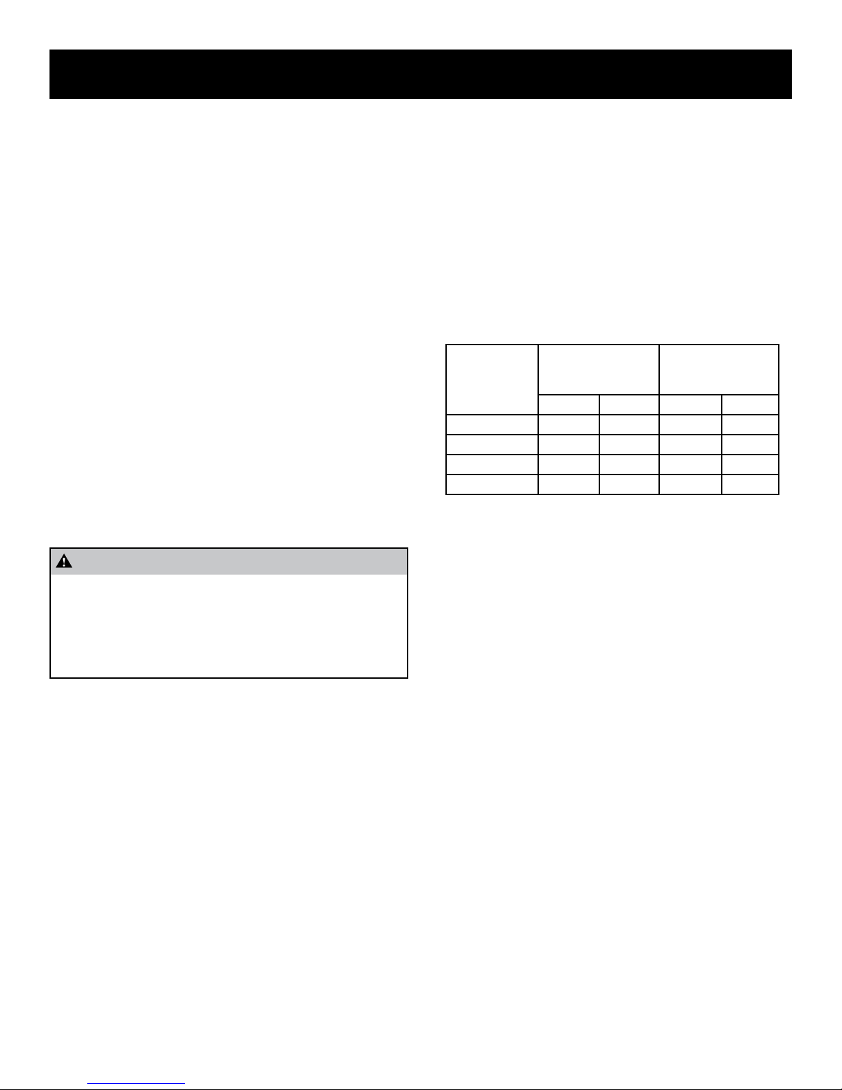
Recommended Gas Pipe Diameter
Pipe Length Schedule 40 Pipe
Inside Diameter
In Inches
Nat. L.P. Nat. L.P.
0-10 feet 1/2 3/8 1/2 3/8
10-40 feet 1/2 1/2 5/8 1/2
40-100 feet 1/2 1/2 3/4 1/2
100-150 feet 3/4 1/2 7/8 3/4
Tubing, Type L
Outside Diameter
In Inches
Leak Testing
WARNING - FIRE OR EXPLOSION HAZARD
Never test for leaks with an open ame. Check all
connections using a commercially available soap solution. A re or explosion may result causing property damage, personal injury or loss of life. Failure
to follow the safety warnings exactly could result in
serious injury, death or property damage.
After gas piping to the replace is complete, all connections must
be tested for gas leaks. This includes pipe connections at the main
gas valve, emergency shutoff valve and exible gas connectors (if
applicable). The soap and water solution can be applied on each
joint or union using a small paintbrush. If any bubbling is observed,
the connection is not sealed adequately and must be retightened.
Repeat the tightening and soap check process until the bubbling
ceases.
Important Note:
When pressure testing the gas supply lines at pressures
greater than ½ psig (14 in. w.c.), the gas supply piping system
must be disconnected from the appliance to prevent damage
to the gas control valve. If the test pressure is less than or
equal to ½ psig (14 in. w.c.), close the manual shut-off valve.
31792-4-1115 Page 9
Page 10
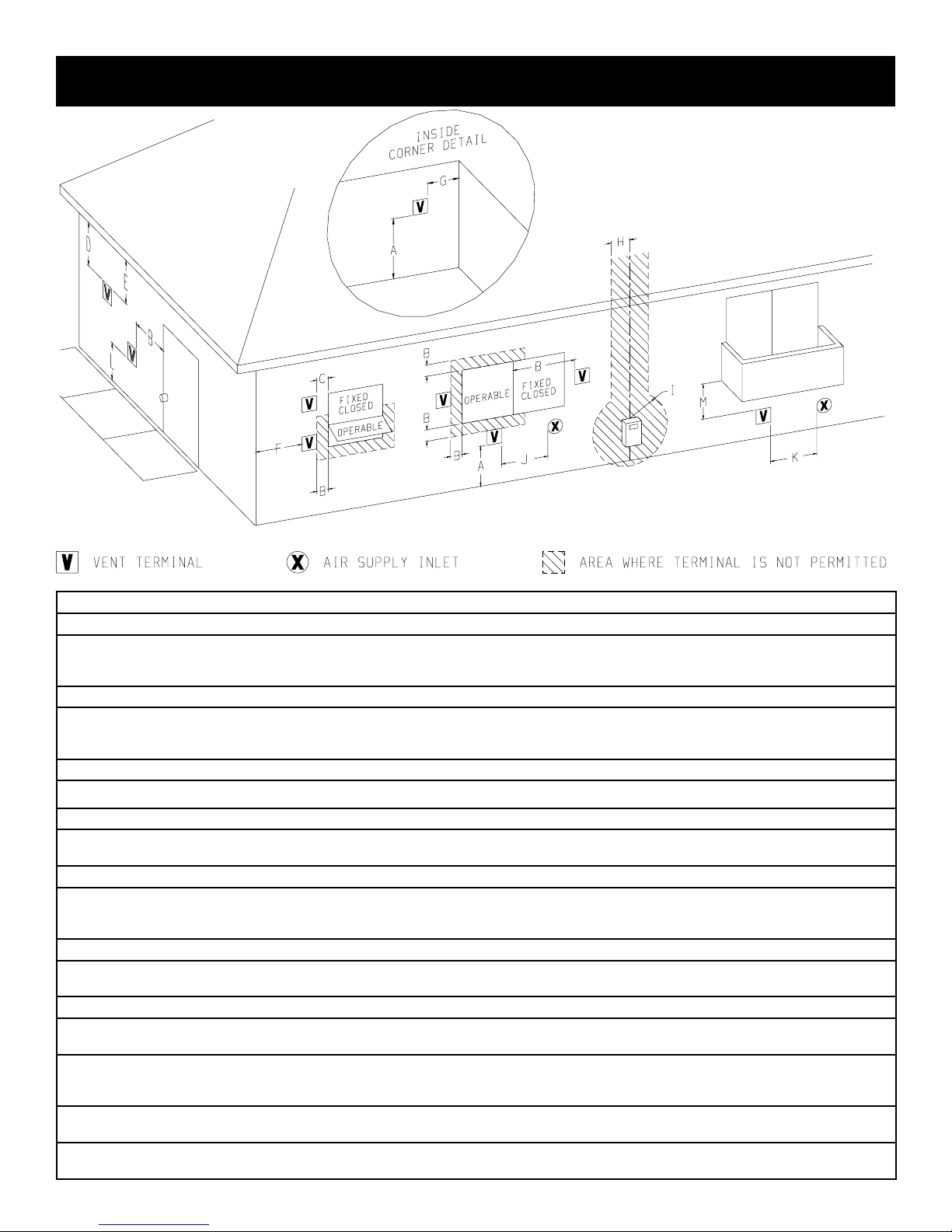
VENT CLEARANCES
A = Clearance above any grade, veranda, porch or balcony 12 in (30 cm)
B = Clearance to window or door that may be opened
C = Clearance to permanently closed windows 0
Vertical clearance to ventilated soft located above the terminal
D =
within a horizontal distance of 2 ft (61 mm) from the center line of the
terminal
E = Clearance to unventilated soft 18 in (46 cm)
F = Clearance of outside corner 12 in (30 cm)
G = Clearance of inside corner 12 in (30 cm)
Clearance to each side of center line extended above meter/regulator
H =
assembly
I = Clearance to service regulator vent outlet 6 ft (182 cm)
Clearance to non-mechanical air supply inlet to building or the com-
J =
bustion air inlet to any other appliance
K = Clearance to a mechanical air supply inlet 3 ft (91 cm) above if within 10 ft (3 m) horizontally
Clearance above paved sidewalk or paved driveway located on public
L =
property †
M = Clearance under veranda, porch deck, or balcony ¥ 18 in (46 cm)
In accordance with the current ANSI Z223.1/NFPA 54, National Fuel
1
Gas Code
A vent shall not terminate directly above a sidewalk or paved driveway
†
that is located between two single family dwellings and serves both
dwellings.
Permitted only if veranda, porch, deck or balcony is fully open on a
¥
minimum of two sides beneath the oor.
For clearances not specied in ANSI Z223.1/NFPA 54 or CSA B149.1,
*
refer to local codes.
Figure 1
US Installation
6 in (15 cm) for appliances ≤ 10,000 Btu/h (3 kW), 9 in (23 cm) for appliances > 10,000 Btu/h (3 kW) and ≤ 50,000 Btu/h (15 kW), 12 in (30
6 in (15 cm) for appliances ≤ 10,000 Btu/h (3 kW), 9 in (23 cm) for appliances > 10,000 Btu/h (3 kW) and ≤ 50,000 Btu/h (15 kW), 12 in (30
1
cm) for appliances > 50,000 Btu/h (15 kW)
18 in (46 cm)
6 ft (182 cm)
cm) for appliances > 50,000 Btu/h (15 kW)
Not applicable
31792-4-1115Page 10
Page 11
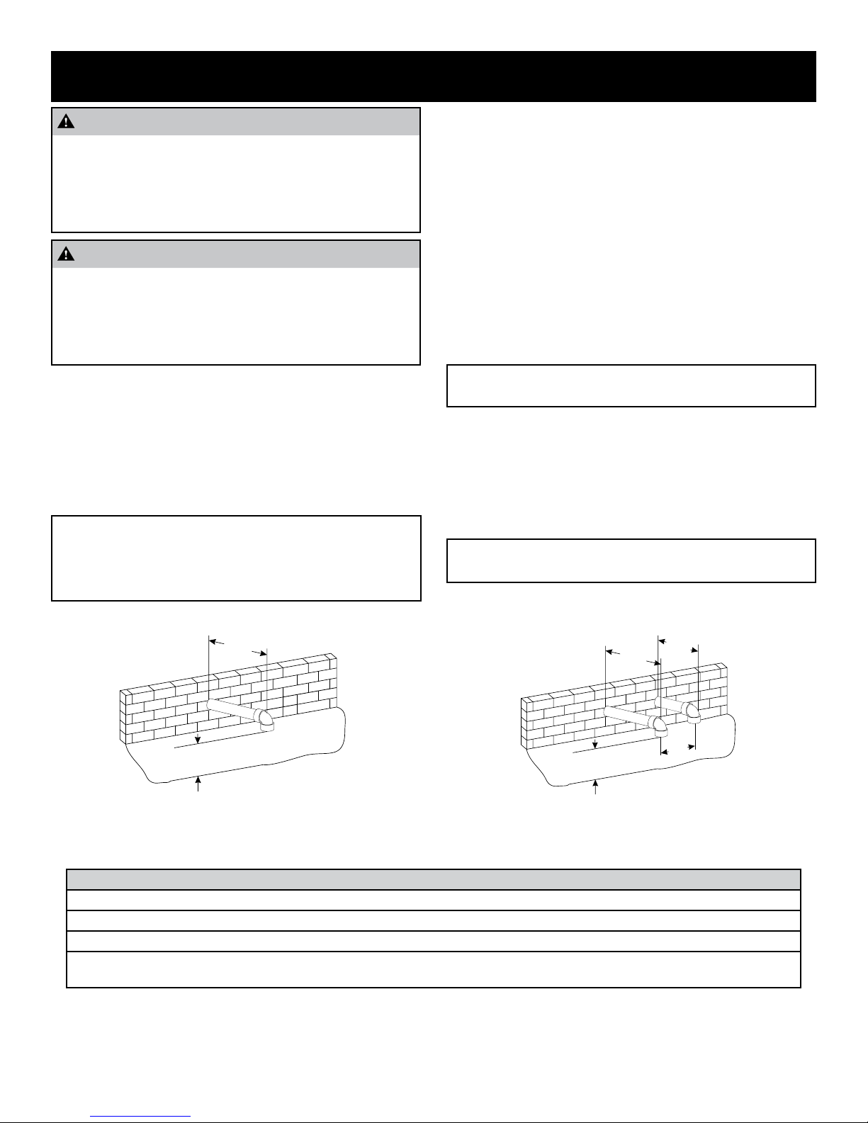
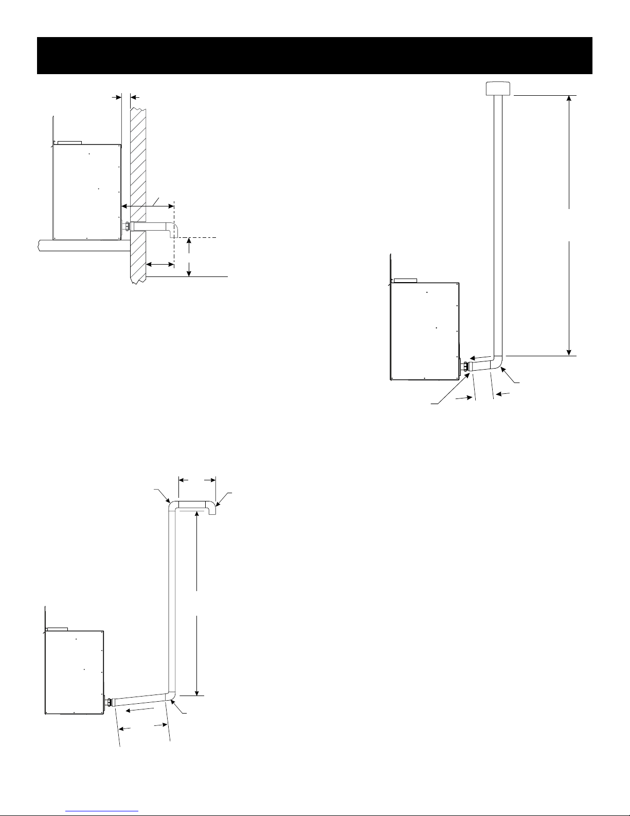
VENTING REQUIREMENTS
12” MIN TO GRADE.
(RECOMMENDED 12” MIN
TO MAX EXPECTED SNOW LEVEL)
6” Min
12” MIN TO GRADE.
(RECOMMENDED 12” MIN
TO MAX EXPECTED SNOW LEVEL)
TYPICAL BOTH PIPES
9” Min
3” Min
24” Max
EXHAUST
INLET
6” Min
WARNING
This appliance must not be vented with any other appliances, even if that appliance is of the condensing type. Common venting can result in severe corrosion of other appliances or their venting and can allow combustion gases to
escape through such appliances or vents. Do not vent the
heater into a replace chimney or building chase.
WARNING
Upon completion of the installation, carefully inspect the en-
tire ue system to assure it is properly sealed. DO NOT use
any vent material other than what is specied in this manual.
Leaks in the ue system can result in serious personal injury
or death due to exposure of ue products, including carbon
monoxide.
The Mantis is classied as a “Category IV” appliance, which requires special venting materials and installation procedures.
Installations can be Conventional (one-pipe) and Direct Vent
(two-pipe). Venting must be completed with 1-1/2 inch diameter
pipe. In selecting a location for installation, it is necessary to pro-
vide adequate clearances for servicing and proper installation.
All vent and combustion air pipes and ttings must be Schedule
40 PVC and meet the ANSI/ASTM Standard D1785. Cement must
conform to ASTM Standard D2564.
Maximum Vent Length is 40 feet with three 90° elbows. The
minimum vent length is twelve inches. Each 90° elbow used
in the vent system will be the equivalent to three feet, and each
45° elbow is equivalent to 1.5 feet, which should be added to
the overall vent length. See Table 1.
It is recommended that the Mantis Power-Vent High-Efciency
Fireplace be located on an exterior wall for ease of venting. The
ue exhaust pipe and inlet air pipe should be located between wall
studs. The required opening for venting is 1-7/8 inch in diameter
for 1-1/2 inch PVC pipe.
For vent clearances refer to Figure 1 pg 10.
The bottom of the exhaust vent terminal and the air intake shall be
located at least twelve inches above grade and must be vented
outside. It is recommended the exhaust and intake be located
twelve inches from the maximum snow level.
The ue pipe must be supported on horizontal vent runs. The ue
pipe needs to be supported every three feet. All horizontal runs of
the ue must be pitched ¼ inch per foot either towards the replace or away from the replace.
Note: If the vent run dips or sags, condensation may become
trapped and cause the unit to not operate properly.
The minimum vent length protruding from outside the wall is six
inches. For two-pipe installation, a minimum distance of three
inches and maximum distance of 24 inches must be maintained
between the pipes. See Figures 2 and 3.
Single ue (one-pipe) installations must have a minimum clearance of two inches on the back of the replace for combustion air.
Note: If vent length requirements are not followed, the unit
will not operate properly.
Figure 2 - Single Flue
Table 1 - Equivalent Vent Length Example
EVL = Equivalent Vent Length
EVL must be greater than or equal to 1’ and less than or equal to 40’
EVL = 90º elbow + 4’ straight pipe + 45º elbow + 2’ straight pipe + 45º elbow + 3’ straight pipe = 15’
EVL = 3’
(90º elbow)
31792-4-1115 Page 11
+ 4’
(straight pipe)
+ 1.5’
(45º elbow)
+ 2’
(straight pipe)
Figure 3 - Colinear Direct Vent
+ 1.5’
(45º elbow)
+ 3’
(straight pipe)
= 15’
Page 12
OR
Cement PVC Joints
VENTING REQUIREMENTS
6” MIN.
12” MAX.
SUPPORT
OUTSIDE
WALL
1/2”
ARMAFLEX
INSULATION OR
EQUIVALENT
(IF REQUIRED)
12” ABOVE
MAXIMUM
EXPECTED
SNOW LEVEL
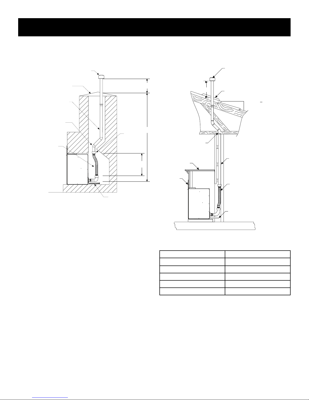
Vent Freezing Protection
When the vent pipe is exposed to temperatures below freezing
(i.e. when it passes through unheated spaces, chimneys, etc.) The
pipe must be insulated with 1/2 inch thick sponge rubber insulation, Armaex-type insulation or equivalent. Insulating pipe is im-
portant to avoid condensate icing.
For proper operation, the ue exhaust must extend 6 inches from
the outside wall before applying an elbow.
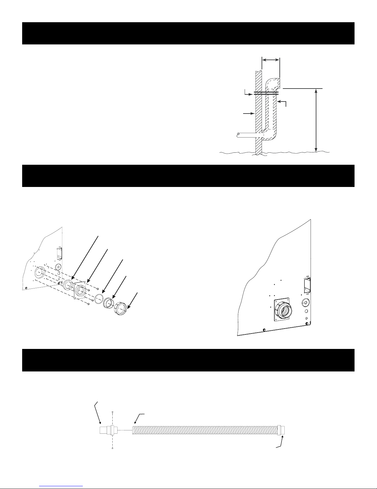
VENT ADAPTOR KITS
Figure 4
The Vent Adaptor Kits provide a transition from the appliance
to the ue and inlet pipes. The Single Flue Horizontal Vent Kit
(PVVK-FC) provides a transition for the piping. No cement is
needed to attach the adaptor to the replace. When installing the
INSTALL FOAM GASKET
FLUE ADAPTOR
O-RING
FLUE CONNECTOR
THREADED
FLUE CONNECT
Figure 5
PVVK-CFA FLEX VENT KIT
ue piping, use the appropriate primer and cement to permanently bond the joints and the pipes. Colinear Adaptor (part number
PVCA) provides a transition for the inlet air piping. See page 16.
Figure 6
The PVVK-CFA ex vent kit is a exible vent hose that is 42” in length. The ex vent kit will be used when installing a Mantis into an
existing replace. The ex vent kit can be cut down, but can only be cut from one end.
Once length is determined, install two 10 x 1/2” screws into the adaptor assembly to secure the adaptor assembly to the ex hose. Using PVC cement, cement all PVC joints of the ex vent kit to the remaining PVC vent run.
Cement PVC Joints
Available from Empire Comfort Systems, Inc.
Cut End
31792-4-1115Page 12
Page 13
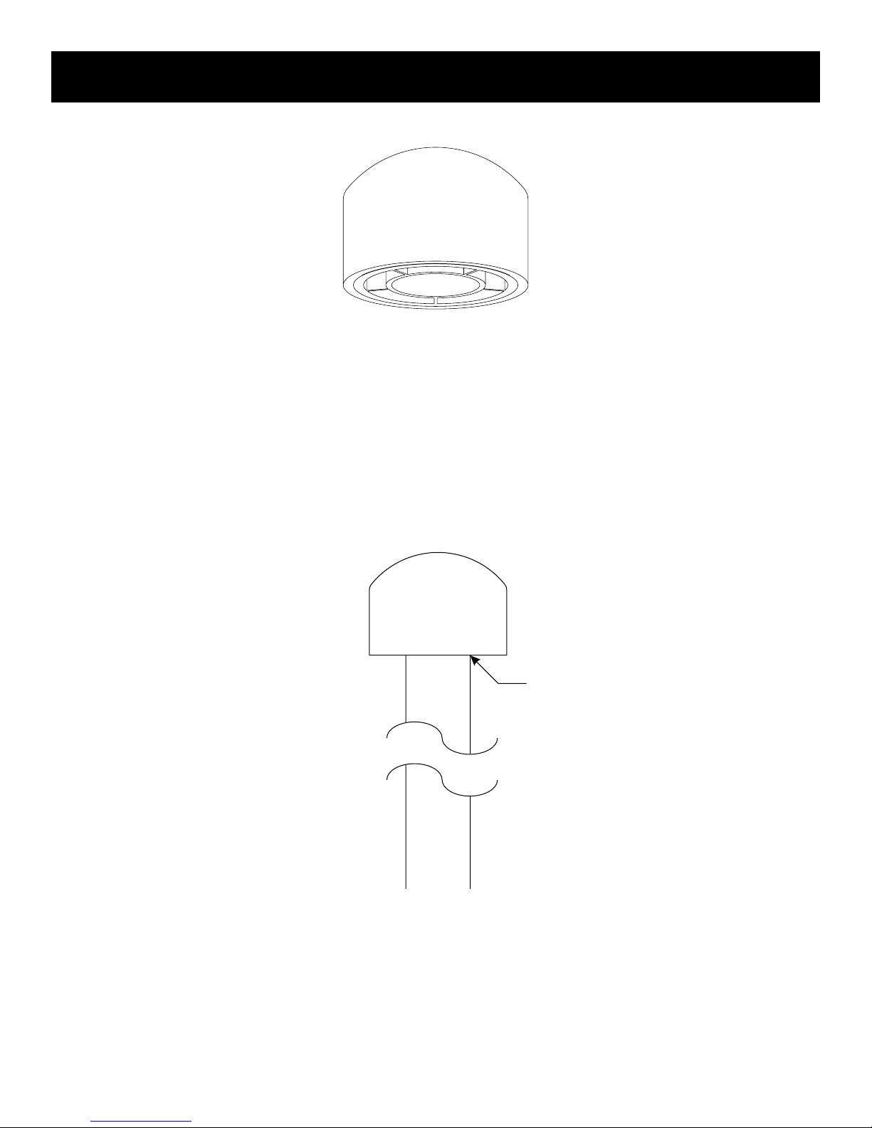
PVVTC TERMINATION CAP VENT KIT
Available from Empire Comfort Systems, Inc.
Termination Cap
PVVTC Vertical exhaust cap for use with 1 1/2” PVC pipe installation.
Termination cap also used with colinear transition plate model PVCT.
Refer to gures 10-15, 19 and 20 for venting examples.
31792-4-1115 Page 13
PVC CEMENT
Page 14
VENT EXAMPLES FOR SINGLE FLUE
2’
SLOPE
12” MIN. TO GRADE
(RECOMMENDED 12” MIN.
TO EXPECTED SNOW LEVEL)
6” MIN.
MIN. 2”
12” MIN.
36’
(11m)
1’
(30.5cm)
SINGLE FLUE ADAPTOR
MODEL #PVVK-FC
SLOPE
Figure 7
Single Flue - Straight Out Back
Min 6” Outside Wall
Min 2” From Fireplace to Wall for Intake Air
Min vent length 12”
H = 1’
V = 36’
(1) - 90° = 3’
Total = 40’
Figure 8 displays a single ue (one-pipe) installation. Because
the distance from the replace to the rst elbow is more than six
inches, the rst 90° elbow must be considered into the total vent
length. The equivalent length of the second 90° elbow also needs
to be added to the total length, but the third elbow does not since it
is the ue terminal. The total horizontal vent length of the ue system is seven feet, and the total vertical length is 27 feet. The two
90° elbows are equivalent to six feet, bringing the total to 40 feet.
90
3 FEET
ELBOW°
(61.0cm)
VENT TERMINAL
90° ELBOW
(NOT COUNTED)
H = 5’ + 2’ = 7’
V = 27’
(2) - 90° = 6’
Total = 40’
27’
(8.2m)
90 ELBOW°
Figure 9
Single Flue - Vertical Vent Run
5’
(1.5m)
Figure 8
Single Flue - Horizontal Tall Vent Run
Example Calculation Max Vent Run 40 feet
FIRST 90
DOES NOT GET COUNTED
WHEN WITHIN 6” (15.2cm)
OFF BACK OF HEATER
° ELBOW
31792-4-1115Page 14
Page 15
VENT EXAMPLES FOR SINGLE FLUE
FLEXIBLE PVC PIPE WITH
1 ½" COUPLING ON EACH END
(MODEL
VENT CAP (SUPPLIED
V
H
42”
SURROUND
FLEXIBLE PVC PIPE
WITH 1 1/2” COUPLING ON EACH END
MODEL #PVVK-CFA
Determining Minimum Vent Height Above the Roof
WARNING: Major U.S. building codes specify minimum chimney
and/or vent height above the rooftop. These minimum heights are
necessary in the interest of safety.
WITH VENT KIT MODEL # PVVK-SV)
GALV. SHEET FLASHING
TO SEAL CHIMNEY
(SUPPLIED BY INSTALLER)
PVC PIPE SWV
(SUPPLIED BY INSTALLER)
(2) - 45 DEG. PVC BENDS
(SUPPLIED BY INSTALLER
IF NECCESSARY)
# PVVK-CFA)
FLEXIBLE GAS
LINE
CUT END
Figure 10 - Venting for Existing Fireplace Installation
2 - 45 DEG. PVC
BENDS (SUPPLIED
BY INSTALLER)
MANTEL
VENT CAP
(SUPPLIED WITH VENT KIT)
MODEL #PVVK-SV
H
FLASHING
12
ROOF PITCH
IS12X
X
PVC PIPE
(SUPPLIED BY INSTALLER)
GAS SUPPLY
Determining Minimum Vent Height Above the Roof
ROOF PITCH H (Min.)
Flat to 6/12 12” (305 mm)
6/12 to 7/12 15” (381 mm)
Over 7/12 to 8/12 18” (457 mm)
Over 8/12 to 16/12 24” (610 mm)
Over 16/12 to 21/12 36” (914 mm)
Figure 11
Single Flue - Vertical Vent Run
with 45 degree elbows
WARNING: Major U.S. building codes specify minimum chimney
and/or vent height above the rooftop. These minimum heights are
necessary in the interest of safety. These specications are summarized in Figure 11.
31792-4-1115 Page 15
Page 16

PVCA HORIZONTAL COLINEAR DIRECT VENT ADAPTOR
SINGLE FLUE HORIZONT
ADAPTER MODEL
4 13/16”
3 11/16”
6 1/8”
7 5/16”
Colinear adaptor
COLINEAR ADAPTER
1. Attach colinear adaptor to back of replace with two screws.
AL
PVVK-FC
2. When adapter is connected, continue with your vent run.
Cementing PVC joint is recommended, but not required on
colinear fresh air intake adaptor.
31792-4-1115Page 16
Page 17

COLINEAR TRANSITION VENT KIT
TRANSITION
OPTIONAL
LEVEL.
Available from Empire Comfort Systems, Inc.
Colinear Transition Plate
The Colinear Transition Kit (Part number PVCT) is available and
can be used to secure the ue and inlet pipes from the Mantis.
When venting vertically, the exhaust pipe termination must be a
minimum of 3 inches above the air inlet.
TERMINATION CAP
AIR INTAKE
PTRAP OR290° ELBOWS
SUPPLIED BY INSTALLER
The ue can be terminated with a PTrap or two 90° elbows. The
Vertical Termination Cap (Part number PVVTC) can also be used
to terminate the ue pipe when using the Colinear Transition Kit.
EXHAUST
PTRAP OR 2 90° ELBOWS
SUPPLIED BY INSTALLER
PVC CEMENT
3” MIN.
PVC CEMENT
PLATE
REQUIRED HEIGHT IS 12” MINIMUM.
IT IS RECOMMENDED TO BE 12” ABOVE
THE MAXIMUM EXPECTED SNOW
OUTDOOR SEALER REQUIRED
Figure 12
Installation of the Colinear Transition Plate
1. Attach the plate to chimney chase, at roof, or outside wall
with four screws. Use outdoor sealant to seal the transition
plate to the surface.
2. Cut inlet air pipe and ue exhaust pipe to correct lengths.
For vertical terminations through the roof or chimney, the air
intake and exhaust pipe termination must be a minimum of
twelve inches above the roof line. It is recommended that
the air intake and exhaust pipe termination be twelve inches
above the maximum expected snow level. See Figures 13
and 14. When venting vertically, the exhaust pipe termination
must be a minimum of three inches above the air intake. Also
refer to local codes. For horizontal termination through outside walls, the minimum pipe length is nine inches for exhaust
pipe termination and six inches for the air intake.
AIR INTAKE
PTRAP OR290° ELBOWS
SUPPLIED BY INSTALLER
PVC CEMENT
3” MIN.
PVC CEMENT
TRANSITION PLATE
REQUIRED HEIGHT IS 12” MINIMUM.
IT IS RECOMMENDED TO BE 12” ABOVE
THE MAXIMUM EXPECTED SNOW LEVEL.
OUTDOOR SEALER REQUIRED
Figure 13
3. Attach the ue and inlet air pipes to the transition plate. Use
the appropriate primer and cement to permanently bond the
joints and the pipes to the transition plate.
31792-4-1115 Page 17
Note: Must maintain a minimum 3” between exhaust outlet and air intake.
Page 18

DIRECT VENT AND COLINEAR VENT EXAMPLES
CO-LINEAR DIRECT
TION CAP
EXHAUST
9”
MIN.
MIN. 2”
6” MIN.
3” MIN.
12" MIN TO GRADE
(RECOMMENDED 12"MIN.
TO MAX EXPECT SNOW LEVEL)
Max Vent Run - 40 ft. Equivalent With Three 90° Elbows
Special Note: The vent terminal 90° elbow and rst 90° elbow
off back of the fireplace, when within six inches (15.2 cm),
do not contribute to the overall vent length measurement.
For each 45° elbow installed in the run, the length of the run
MUST be reduced by 1.5 feet (45 cm). Reduce the length of the
run three feet (91.4 cm) for every 90° elbow.
3” MIN.
12” MIN.
Note: Exhaust must be a
minimum of 3 inches above
air intake inlet.
CO-LINEAR TRANSITION
90° ELBOW
3 FEET
AIR INTAKE
SIDE VIEW
FLAT ROOF
PTRAP
MODEL PVCT
10’
EXHAUST
AIR INTAKE
OPTIONAL
VERTICAL TERMINA
MODEL PVVTC
3” MIN.
12” MIN.
protruding from the outside wall is six inches (15.2 cm) for air intake and nine inches for exhaust. See Figure 15.
Note: Horizontal discharge 90° elbow must be pointed downward.
See Figure 15. All horizontal runs require either a 1/4” per foot rise
to run condensation back to the fireplace, or a 1/4” per foot down-
ward slope to run condensation away from the fireplace.
Note: All PVC vent run piping can be purchased at a local hard-
ware store. Schedule 40 PVC pipe should be used and cemented.
PVCA Horizontal Colinear Direct Vent Adaptor, PVVTC Cap, PVVK-CFA Flex Kit and PVVK-SH Horizontal Vent Adaptor Kit are
available from Empire Comfort Systems, Inc.
In both vertical and horizontal colinear direct vent applications,
a colinear transition plate model PVCT can be used to minimize
clearances between intake and exhaust pipes.
For horizontal colinear direct venting, exhaust and intake air, cap
pipes with 90º elbows, pointed downward.
Note: If transition plate (model PVCT) is used, the measurement
for center to center of the pipes will be 2.5”. If the transition plate
(model PVCT) is not used, the measurement for center to center
of the pipes can be 3” to 24” maximum.
SLOPE
VENT ADAPTER
MODEL PVCA
SINGLE FLUE ADAPTER
MODEL PVVK-FC
SLOPE
10’
5’
6’
H = 5’ + 6’ = 11’
V = 10’+ 10’= 20’
(3) 90° = 9’
TOTAL= 40’
FIRST 90
° ELBOW
DOES NOT GET COUNTED
WHEN WITHIN 6” (15.2cm)
OFF BACK OF HEATER
Figure 14
Calculation example of vent run maximum 40 feet
Figure 14 displays a two-pipe installation. Because the distance
from the replace to the rst elbow is more than six inches, the
length allowance for the rst 90° elbow must be added to the total
vent length. The equivalent length of the second 90° elbow also
needs to be added to the total length. The third elbow also needs
to be included. The equivalent length of the PTrap does not need
to be added since it is the termination. The total horizontal vent
length of the ue system is eleven feet, and the total vertical length
is 20 feet. The three 90° elbows are equivalent to nine feet, bring-
ing the total to 40 feet.
Note: The exhaust must be a minimum of three inches above the
inlet air pipe. The ue must be at least twelve inches from the roof
line, and it is recommended to be at least twelve inches above the
maximum expected snow level as indicated in Figures 13 through
20.
Note: On horizontal runs, a P.V.C. support clamp needs to be installed every three feet. No “sags” in horizontal vent runs; water
will settle in the pipe.
When installing a colinear horizontal, the minimum vent length
90° ELBOW
3 FEET
Figure 15
31792-4-1115Page 18
Page 19

DIRECT VENT AND COLINEAR VENT EXAMPLES
ADAPTER
MODEL PVCT
12” MIN.
EXTERIOR GRADE
SINGLE FLUE ADAPTER
MODEL PVVK-FC
CO-LINEAR DIRECT VENT
MODEL PVCA
Figure 16
In direct vent applications, the minimum distance between the two
pipes is three inches and the maximum distance is 24 inches. The
ue exhaust and air inlet can be terminated with either a PTrap or
two 90° elbows as shown in Figures 12, 13 and 14. The Vertical
Termination Cap shown on page 13 (Part number PVVTC) can
also be used.
Figure 17
In both vertical and horizontal colinear direct vent applications,
a colinear transition plate model PVCT can be used to minimize
clearances between intake and exhaust pipes.
For exhaust and intake air, cap pipes with any of the following:
Vertical termination cap (model #PVVTC), PTrap, or two 90º elbows. When transition plate (model PVCT) is used, two termination caps (model PVVTC) may NOT be used.
Note: If transition plate (model PVCT) is used, the measurement
for center to center of the pipes will be 2.5”. If the transition plate
(model PVCT) is not used, the measurement for center to center
of the pipes can be 3” to 24” maximum.
31792-4-1115 Page 19
Page 20

DIRECT VENT AND COLINEAR VENT EXAMPLES
ADAPTER
AT
MODEL
SHEET
WITH (4) SCREWS.
USE OUTDOOR SEALER
BETWEEN PLA
H
FLASHING
REQUIRED
H
REQUIRED HEIGHT IS 12”
MINIMUM. IT IS RECOMMENDED
TO BE 12” ABOVE THE
EXPECTED SNOW LEVEL.
3” - 24”
OPTION
OPTION
AIR INTAKE
PTRAP, 2 90° ELBOWS (SUPPLIED
BY INSTALLER) OR TERMINATION CAP
MODEL PVVTC. PTRAP TO FACE
AWAY FROM ROOF.
EXHAUST
TERMINATION CAP
MODEL PVVTC, PTRAP
OR 2 90° ELBOWS
SLOPE
Note: Exhaust must be a minimum of 3” above air intake inlet.
EXHAUST: VERTICAL TERMINATION
CAP 1.5” MODEL PVVTC, PTRAP OR
2 90° ELBOWS
TACH OPTIONAL VENT KIT
PVCT PLATE TO GALV.
FLASHING (CHASE)
2.5”- 24”
TE AND CHASE.
45° ELBOW
23 1/2”
(59.7cm)
Colinear Direct Vent - Insert Installation
Figure 18
FLAT ROOFFLAT ROOF
AIR INTAKE
PTRAP OR 2 90° ELBOWS
(SUPPLIED BY INSTALLER)
3” MIN.
45° ELBOW
FLEX PVC PIPE
WITH 1.5” COUPLING
ON EACH END
MODEL PVVK-CFA
CO-LINEAR
DIRECT VENT
MODEL PVCA
AIR INTAKE
EXHAUST
SINGLE FLUE
MODEL PVVK - FC
Determining Minimum Vent Height Above the Roof
ROOF PITCH H (Min.)
Flat to 6/12 12” (305 mm)
6/12 to 7/12 15” (381 mm)
Over 7/12 to 8/12 18” (457 mm)
Over 8/12 to 16/12 24” (610 mm)
Over 16/12 to 21/12 36” (914 mm)
Colinear Direct Vent - Pitched Roof Installation
Figure 19
WARNING: Major U.S. building codes specify minimum chim-
ney and/or vent height above the rooftop. These minimum
heights are necessary in the interest of safety. These specications are summarized in Figure 19.
31792-4-1115Page 20
Page 21

TUBE LENGTH
PVVK-24H AND PVVK-48H CO-AXIAL VENT KIT
Available from Empire Comfort Systems, Inc.
Step 1. Install foam gasket on back side of co-axial direct vent
adaptor.
Step 4. Install silicone around connection between co-axial
adaptor and co-axial air-inlet duct.
Step 2. Attach co-axial direct vent adaptor and gasket (4 screws)
to the rear of replace.
Step 3. Attach co-axial air-inlet duct to rear of replace (six
screws).
MINIMUM VENT LENGTH
4 1/2”
3 13/16”
MINIMUM
Step 5. Slide co-axial vent pipes into co-axial adaptor.
Cut the PVC co-axial pipes at this time.
Minimum horizontal vent length 4 1/2” (11.4 cm)
Minimum tube length 3 13/16” (9.7 cm)
31792-4-1115 Page 21
Step 6. Direct vent co-axial venting is completed.
Page 22

MUST
ARD.
PVVK-24H AND PVVK-48H CO-AXIAL VENT KIT (cont.)
45° ELBOW
47.5”
(1.2m)
1 9/16”
Horizontal Venting Maximum 47.5” (1.2 m) with 45° elbows.
Inner 1-1/2 inch pipe and outer three inch pipe 45° elbows
can be purchased from a local hardware store.
Figure 20
EXHAUST OPENING
BE POINTED DOWNW
Direct Vent System Building Exterior View
Figure 21
4 3/32”
Figure 23
47.5”
(1.2m)
Maximum Horizontal Venting - 47 1/2” (1.2 m)
Minimum Horizontal Venting - 4” (10.2 cm)
Figure 22
31792-4-1115Page 22
Page 23

PVVK-24H AND PVVK-48H CO-AXIAL VENT KIT (cont.)
DIRECT VENT
FLUE KIT
FLUE CENTER
12” (30.5 cm)
MINIMUM
EXTERIOR GRADE
GAS SUPPLY
SURROUND
MANTEL
FLOOR PROTECTION
Minimum Exterior Grade Dimension
1 1/4”
(3.2cm)
MIN.
FLUE CENTER
12”
(30.5cm)MIN.
EXTERIOR GRADE
Figure 24
Figure 26
Horizontal Venting
FLUE CENTER
12”
(30.5cm)
MIN.
EXTERIOR GRADE
Figure 25
Minimum Exterior Grade Dimension - Existing Fireplace
Installation
31792-4-1115 Page 23
Page 24

ACCESS
PANELS
ROUGH FRAMING DIMENSIONS
B
A
C
Figure 27
ACCESS
PANELS
Figure 28
Index Letter Single Vent Direct Vent and Colinear Vent Coaxial Vent Flex Vent
A 19-1/2” minimum* 19-1/2” minimum* 18-1/2” minimum 23-3/4” minimum
25” minimum
27-3/4” maximum when using FHKQ28 Surround Kit
B
28-1/2” maximum when using FFKQ28 Surround Kit
29-1/2” maximum when using FIKQ28 Surround Kit
32” maximum when using FWKQ28 Surround Kit
28-1/2” minimum, 31” recommended for service
33” maximum when using FHKQ28 Surround Kit
C
34” maximum when using FFKQ28 Surround Kit
37” maximum when using FIKQ28 Surround Kit
34” maximum when using FWKQ28 Surround Kit
* When using a 2” radius 90° street ell on the ue exhaust, add 5-1/2”.
31792-4-1115Page 24
Page 25

INSERT INTO MASONRY FIREPLACE
Figure 29
Index Letter Single Vent Direct Vent and Colinear Vent Flex Vent
A 19-1/2” minimum* 19-1/2” minimum* 23-3/4” minimum
27-3/4” maximum when using FHKQ28 Surround Kit
B
C
* When using a 2” radius 90° street ell on the ue exhaust, add 5-1/2”.
28-1/2” maximum when using FFKQ28 Surround Kit
29-1/2” maximum when using FIKQ28 Surround Kit
32” maximum when using FWKQ28 Surround Kit
28-1/2” minimum, 31” recommended for service
33” maximum when using FHKQ28 Surround Kit
34” maximum when using FFKQ28 Surround Kit
37” maximum when using FIKQ28 Surround Kit
34” maximum when using FWKQ28 Surround Kit
25” minimum
31792-4-1115 Page 25
Page 26

CLEARANCE TO COMBUSTIBLES
BB
6-1/4”
MIN
ACCESS
PANEL
ACCESS
PANEL
12”
18”
24”
8”
6”
4”
COMBUSTIBLE TRIM AND MANTELS
ALLOWED IN SHADED AREA
44-3/4”
CEILING
4-3/4”
ACCESS
PANEL
A
A
ACCESS
PANEL
C
Figure 30 Figure 32
Figure 31
Insert Clearances
A Rear Wall to Fireplace 2” (1-1/4” for coaxial venting)
B Side Wall to Fireplace 0”
C Corner Installation 0”
C
Note: The Mantis Power-Vent High-Efciency Fireplace has been tested and approved for zero clearance to combustible materials. It
is recommended that clearances as listed above should be maintained to allow for removal of the product for servicing.
Mantel and Ceiling Clearances
Figure 33
31792-4-1115Page 26
Page 27

35”
33-7/16”
35”
29-3/8”
PVVK-CFA
FLEX VENT KIT
23-1/2”
24-3/4”
MIN.
6-1/2”
SPECIFICATIONS
17-3/16”
3-9/16”
FLUE OUTLET
24-3/4” MIN
11/16"
1-3/8"
24-3/4" MIN
16-15/16"
Figure 34
42-7/8"
32-1/2"
3-9/16"
Figure 37
Fireplace - 42-7/8 inch Louverless Surround Kit
FHKQ28(BL,SS) - Contains surround brackets and air deector
Figure 35
Figure 36
Fireplace with Flex Vent
31792-4-1115 Page 27
Figure 38
Fireplace In Wall - 35 Inch Picture Frame Surround
FWKQ28(BL,CM,HP,SS) - Contains surround, hood, and lower
front
Figure 39
Fireplace - 35 Inch Surround Kit
FFKQ28(BL,CM,HP,SS) - Contains surround, hood, & lower front
Page 28

38”
FLUE
OUTLET
AIR INLET
ELECTRIC
CORD
GAS LINE
OPENING
1-1/8”
7-5/16”
4-3/16”
2-5/8”
6-1/8”
3-9/16”
13/16”
1”
28”
SPECIFICATIONS
30-7/8”
Figure 40
Fireplace - 38 Inch Surround
FIKQ28(BL,CM,HP,SS) - Contains surround, hood, & lower front
4”
8”
Figure 42
Clearance for Access Panel In-Wall Fireplace
See Gas Connection Instructions.
Figure 41
31792-4-1115Page 28
Page 29

GAS CONNECTION INSTALLATION
ACCESS
CAUTION
The gas supply line to the heater must be installed under
conditions which will allow for easy removal of the heater
from its location for servicing of the heater. For replace
insert installation, incorporate a loop into the exible gas
line.
Under no circumstances should the gas supply line to the
appliance be installed in a way that would prevent the appliance from being serviced or inspected.
GAS SUPPLY LINE TO FIREPLACE
1. Pull the factory installed exible gas line through the hole in
the back panel. See Figures 43 and 44.
2. Connect the gas supply line to exible gas hose. Ensure that
exible gas hose is not kinked after tting gas supply line. Any
excess exible line can be pushed back into the replace.
3. Place rubber grommet that is supplied in hardware packet
over the exible gas line and secure in the hole in the back of
the appliance.
PUSH IN PLUG
PLATE
Figure 43- Fireplace Mantis
Gas Connection - In-Wall Units
1. Remove the access plate on the left side of the cabinet by
removing three screws as shown in Figure 44. Put the screws
aside.
2. Push the factory supplied exible gas line through the access
hole on the side.
3. Remove the knockout from the access plate and insert the
exible gas line through the hole.
4. Secure the access plate to the cabinet with three screws removed in Step 1.
5. A plastic push in plug is supplied in the hardware package,
insert the plug into the 1-3/8 inch hole in the back of the re-
place.
6. Insert the rubber grommet into the hole in the access plate to
protect the exible gas line.
Figure 44
Gas Connection, Fireplace Mantis In-Wall Units
31792-4-1115 Page 29
Page 30

LIGHTING INSTRUCTIONS
FOR YOUR SAFETY READ BEFORE LIGHTING
WARNING: IF YOU DO NOT FOLLOW THESE INSTRUCTIONS EXACTLY, A FIRE OR EXPLOSION MAY
RESULT CAUSING PROPERTY DAMAGE, PERSONAL INJURY, OR LOSS OF LIFE.
A. BEFORE LIGHTING smell all around the appliance area
for gas. Be sure to smell next to the oor because some
gas is heavier than air and will settle on the oor.
WHAT TO DO IF YOU SMELL GAS
• Do not try to light any appliance
• Do not touch any electrical switch
• Do not use any phone in your building.
• Immediately call your gas supplier from a neighbor's
phone.
• Follow the gas supplier's instructions.
• If you can not reach your gas supplier, call the re
department.
LIGHTING INSTRUCTIONS
1. STOP! Read the safety infor-
mation above.
2. Turn off the remote thermostat
if used.
3. Open bottom louver assembly,
or open the service access
panel..
4. Turn off all electric power to
the appliance.
5. Turn gas line valve to “ON.”
6. Wait ve minutes to clear out any gas. Then smell for
gas, including near the oor. If you smell gas, STOP!
Follow “A” in the safety information above. If you do not
smell gas, go to the next step.
7. Turn on all electric power to the appliance.
8. Turn on the remote thermostat if used, and set thermostat to desired setting. If remote is not used, activate
the appliance using the display panel.
B. Use only the wall switch or remote control switch to
turn the gas control on/off. Any attempted repairs or
adjustments should be performed by a qualied service
technician. Applying force or attempted repair may result
in a re or explosion.
C. Do not use this appliance if any part has been under
water. Immediately call a qualied service technician
to inspect the appliance and to replace any part of the
control system and any gas control which has been
under water.
9. This appliance is equipped with an ignition device that
automatically lights the burner. Do not try to light the
burner by hand.
10. If the appliance will not operate, follow the instructions
“TO TURN OFF GAS TO APPLIANCE,” and call your
service technician or gas supplier.
11. Close bottom louver assembly or close the service access panel.
OFF
ON
TO TURN OFF GAS TO APPLIANCE
1. STOP! Read the safety information above.
2. Open bottom louver assembly, or open the service ac-
cess panel.
3. Turn off all electric power to the appliance.
4. Turn gas line valve to "OFF."
5. Close bottom louver assembly, or close service access
panel.
31792-4-1115Page 30
Page 31

WIRING
N
GREEN/YELLOW
BROWN
BROWN
BLACK
WHITE
YELLOW
VIOLET
RED
RED
WHITE
BLUE
YELLOW
RX module
BROWN
BROWN
RED
BLACK
HI LIMIT
MODULATOR COIL
RED
BLACK
YELLOW
FLAME
SENSOR
AIR
PRESSURE
SWITCH
TRANSDUCER
THERMISTER
RED
RED
WATER LEVEL
DETECT
DISPLAY
PANEL
RIBBON
HOT
SURFACE
IGNITOR
CAPACITOR
WARNING
Potential risk of re, electric shock, and personal
injury. Take precautions to reduce such risks.
CAUTION
Label all wires prior to disconnection when servicing
controls. Wiring errors can cause improper and
dangerous operation. Verify proper operation after servicing.
This appliance is equipped with a three-prong [grounding]
plug for your protection against shock hazard and should be
plugged directly into a properly grounded three-prong receptacle. Do not cut or remove the grounding prong from this
plug. For an ungrounded receptacle, an adapter, which has two
prongs and a wire for grounding, can be purchased.
Proper line voltage polarity must be maintained in order for the
control system to operate correctly. Verify the incoming neutral line
is connected to the white wire and the incoming “hot” line is connected to the black wire. The replace will not operate properly
unless the polarity and ground are correct.
GREEN
BLACK
BLACK
BLACK
RED
WHITE
WHITE
ON
OFF
BROWN
BLUE
WHITE
RED
BLUE
BLACK
SWITCH
MAIN
POWER
BLUE
BLUE
GREEN
BLACK
GREEN/YELLOW
MAI
LINE
GAS
VALVE
FLUE
FAN
PUMP
COMFORT
FAN
START UP CHECK LIST
WARNING
BEFORE OPERATING THIS APPLIANCE, CAREFULLY
READ THE FOLLOWING.
31792-4-1115 Page 31
Figure 45
1. Verify the gas line service does not exceed 10.5 in. w.c.
and is not below 5.0 in. w.c. for natural gas, nor exceeds
13.0 in. w.c. or is below 11.0 in. w.c. for LP gas.
2. Check and inspect the appliance for gas leaks. In the event
of gas leaks, cut off the gas supply to the replace immediately and call your gas supplier. Verify the gas line has been
purged.
3. Verify that all exhaust and inlet air pipes are unobstructed and
properly joined.
4. Visually verify the burner is free of dust and debris.
5. Verify that all panels are secured in place and that the glass
assembly door has been locked in position.
6. Verify that the polarity of the connections are correct and the
line voltage power leads are secure.
7. After verifying and checking all the above points, proceed to
lighting instructions. Refer to Page 30.
Note: Verify the surround is installed per the instructions included with the kit.
Page 32

START UP AND ADJUSTMENTS
A. With main electrical power to the replace turned off, install
three AAA sized 1.5V batteries into the remote. Set up remote
per instructions on pages 34 - 40. After the remote is set up,
ensure that the remote is turned on and active. The remote
display must show “Auto,” Manual” or “Pilot.”
Figure 46
B. Turn on the main electrical power to the replace. See Fig-
ure 47. The red and green control board LED lights will begin
ashing alternately. Each light will ash four times. Then the
replace will enter standby and the green LED light will begin
to slowly ash. Verify power is on by checking if there is power
to the control board. If the replace has power, the green LED
light on the control board will be ash slowly.
Figure 47
C. The Display Panel board should be energized, and a “double
dash symbol” (- -) the power light will be displayed. See Fig-
ure 48. The remote receiver automatically links to the remote
transmitter’s signal. If the replace does not respond to the
remote when in remote mode as indicated by
the double dash symbol, turn the main power off
(Figure 45) and make sure the remote is on and
active before turning main power back on.
D. Turn on the main gas supply.
Sequence of Operations
1. Start the replace with the remote, or press the display panel’s
“Mode Select” button (Figure 48) to start the replace manually. The Display Panel will energize, and the desired ame
level will be displayed.
2. The inducer will activate and perform a safety test lasting 45
seconds. The ignition sequence will initiate after this test.
3. The igniter (HSI) will energize and start to glow red.
4. After 20 seconds, the gas valve will open and ignite the burner
on high. The ame sensor will verify the ame is present within six seconds and the green LED light on the control board
will illuminate.
5. The gas valve will adjust manifold pressure and inducer speed
to match desired ame level.
Note: The replace will always ignite on Level 5 (High) prior to
adjusting to the ame level on the display panel.
Note: The entire ignition sequence takes approximately one
minute, 15 seconds to complete.
6. Use the “Manual Flame Level Adjustment” buttons on the display panel (Figure 48) or the remote control to change the
ame level setting.
Note: When changing from a low ame level to a higher ame
level, the replace will automatically increase to Level 5 (High)
prior to proceeding to the desired ame level. This is to ensure
consistent operation.
The table below outlines the BTU input rate of the burner for each
ame level.
Flame Level BTU Input
5 20,000
4 17,500
3 15,000
2 12,500
1 10,000
7. As the Mantis warms up, the circulating blower will activate,
starting on Low speed (l). The Low Blower speed will display
when the blower turns on.
8. As the Mantis continues to operate, the speed of the circulating blower will increase, and the symbols for Medium (2) and
High (3) will appear.
CAUTION: If the replace experiences an
unexpected loss of power while the remote is
operating in thermostatic mode, the remote’s
thermostatic function will need to be manually reset after power is restored in order for
the replace to resume normal operation.
Press the remote’s power button to turn it off
then back on to reset the thermostatic function.
Figure 48
31792-4-1115Page 32
Page 33

START UP AND ADJUSTMENTS
Display Backlight
The display panel back light will automatically turn off ve seconds
after an input (either manual or remote) is acknowledged. The
back light will automatically turn on when a new input is acknowl-
edged. To turn the back light on manually, press the “Display Backlight” button on the bottom left of the display panel (Figure 48).
Shut Down Instructions
To turn the replace off, simply push “OFF” on the remote or push
the display panel’s mode select button to “OFF”. See Figure 49.
DO NOT cut the main electrical power to the replace.
The circulating blower will continue to operate after the burner is
turned off. The blower will stop automatically once the replace
has cooled down.
Checking Manifold Pressure
Both Propane and Natural gas valves have a built-in pressure
regulator in the gas valve. Natural gas models will have a manifold
pressure of approximately 3.5 in. w.c. at the valve outlet, with the
inlet pressure to the valve at 5.0 in. w.c. to 10.5 in. w.c. Propane
gas models will have a manifold pressure approximately 7.0 in.
w.c. at the valve outlet, with the inlet pressure to the valve from
11.0 in. w.c. to 13.0 in. w.c.
A pressure tap accessible for test gauge connection, is located on
the outlet side of the gas control.
Blower Operation
The circulating air blower will automatically engage and increase
in speed depending on the operation of the burner. In most circum-
stances, the circulating blower will start three to ve minutes after
ignition of the burner.
Once the replace is turned off or the call for heat has been satised, the circulating blower will continue to run. The blower will
automatically adjust its speed and turn off as the replace cools
down.
High Altitude
The Mantis can be installed to altitudes up to 10,000 feet in the
U.S., and up to 4,500 feet in Canada. The installation must meet
the requirements of the National Fuel Gas Code or local jurisdic-
tions.
Humidier Operation
When the replace has been running, the “AUX” symbol on the
display panel (Figure 48) will turn on to signal that the pump has
been activated. Refer to Page 42 - Automatic Humidier Opera-
tion.
Paint Curing - First Firing
The Mantis Power-Vent High-Efciency Fireplace has been painted with the high quality heat resistant silicon paint. To ensure that
the paint is properly cured, allow the replace to operate with both
burners on, for approximately one hour. During the initial ring of
the appliance, it is common for smoke to appear.
CAUTION
DO NOT touch the surface of the replace. The paint will
soften during the initial operation, and will harden over
time. Once the paint is cured, it will not soften again.
• To prevent triggering of smoke alarms, supply proper ventilation to the room where the unit is installed.
• DO NOT clean the replace with any caustic or abrasive
cleaning solutions. This will damage the surface.
• Any damage to the painted surfaces should be repaired only
with authorized paint available from your Mantis Dealer.
31792-4-1115 Page 33
Page 34

REMOTE INSTRUCTIONS
The remote control and its LCD screen lets you make full use of
your replace’s potential. In particular it enables you to adjust the
replace’s operating parameters, program its timer, and continu-
ously monitor room temperature to control operation.
A room temperature sensor is built into the remote control to ensure accurate measurement of temperature in the room to be
heated, at whatever point the user wishes, and without having to
install inconvenient thermostat cables.
When the remote is turned on the back-lighting of the remote control screen illuminates as soon as you press any button.
ATTENTION
If the remote control is switched off because there are no bat-
teries in it, it cannot be used to control the replace and the
replace’s display panel must be used instead (see page 32).
When using the replace’s display panel for operation only key
functions remain enabled: on, off and manual control of the
ame levels.
CAUTION
Keep the remote control away from direct heat and water.
Keep the remote control away from children.
The remote control must always be kept near the replace (i.e.
within a radius of about 16 feet of it) to ensure correct transmission of measured temperature values.
A
G
Index
Description
No.
A Temperature sensor location
B Back-lit LCD display
Power button. Use this button to switch the remote On,
C
Off or place the remote in Standby (PILOT) mode.
The Mode Select (Manual - Thermostatic) button
switches the remote from Manual (MAN) mode to
D
Thermostatic (AUTO) mode. When using this button
in conjunction with other buttons you can also access
menus like the clock setting menu.
Use the up and down button for adjusting the ame
E
level and adjusting the sleep and timer settings.
MENU button for accessing sleep and program
F
menus.
G Base and battery compartment.
Figure 49 - LCD Remote Control
B
C
D
E
F
31792-4-1115Page 34
Page 35

REMOTE INSTRUCTIONS
Index
No.
1
2
13
15
14
16
1
MAN
AUTO
PILOT
3
4
Description
Remote function mode symbols
(MANUAL - AUTOMATIC - PILOT)
12
2 Symbol for remote communication to replace
Keypad lock symbol. This symbol appears when keypad is
3
locked.
Low battery symbol. When this symbol appears without
4
ashing, the batteries must be replaced.
The temperature currently measured by the remote con-
5
trol’s built-in sensor for the area around the remote control.
Temperature units of measurement
6
(Celsius - Fahrenheit).
Symbol identifying room temperature measured by the
7
built-in sensor.
The thermostatic mode set temperature. This symbol does
8
not appear in MANUAL mode.
Clock. The clock functions as a countdown when the
9
SLEEP function is in use.
10 Symbols indicating the current day.
TIMER symbol. If this symbol does not appear, the TIMER
is not active. If only the outline of the symbol appears, the
11
TIMER is active. A solid black symbol indicates that you are
in the TIMER setting menu.
SLEEP function symbol. If this symbol does not appear, the
SLEEP function is not active. If only the outline of the
symbol appears, the SLEEP function is active, meaning
12
that the stove will switch off at the end of the countdown
period set by the user and shown by symbol 9. A solid black
symbol indicates that you are in the SLEEP setting menu.
Flame symbol, indicating the current ame power. If ame
13
power is at level 5, the MAX message also appears.
Clock setting symbol. When this symbol appears, you can
14
adjust the clock setting displayed by the digits 9.
Flame power bars: one bar = low, ve bars = high. These
15
bars only appear when the stove is in MANUAL mode.
Digits identifying the weekly TIMER program currently
16
selected.
Figure 50 - The Remote Control Display
11
10
9
8
6
6
NOTE: The program symbol
ame symbol
can appear in two ways: Solid black or Outline
Solid symbols indicate that you are currently in that function’s setting menu.
For example, If the sleep symbol
, sleep symbol , and
appears in solid black,
you are currently in the sleep timer setting menu and can use the
5
7
up and down button (E in Figure 51 )to change the sleep timer.
E
Figure 51
Outline symbols mean that the function is active but that settings
cannot be changed unless you rst enter the setting menu. When
you enter the setting menu, the symbol turns solid black again.
For example, If the sleep symbol appears only in outline, the sleep
timer is active and functioning.
Battery Type and Replacement
The batteries are housed in the base of the remote control. The
device requires 3 AAA 1.5V batteries. The Low Battery Symbol
on the remote control display tells you when the batteries
are running out. If the low batteries symbol
batteries are nearly discharged and the remote control is about to
lose power.
ATTENTION
The batteries may need to be replaced frequently due to the
remote control’s multiple functions.
CAUTION
When replacing the batteries, take care to respect the polarity
symbols inside the remote control’s battery compartment.
appears, the
31792-4-1115 Page 35
Page 36

REMOTE INSTRUCTIONS
SETTINGS REQUIRED PRIOR TO INITIAL START-UP
Setting the Time and Day
When batteries are inserted into the remote control, as during initial setup or when replacing the batteries, the remote will auto-
matically enter the clock setting menu. To reset the clock without
removing the batteries, simultaneously press the “O” and Mode
buttons on the remote control for ve seconds to enter the clock
setting menu (Figure 52).
The days of the week are indicated by two-letter codes.
MO = Monday
TU = Tuesday
WE = Wednesday
TH = Thursday
FR = Friday
SA = Saturday
SU = Sunday
Note: If the keypad is not used for 7 seconds, the remote control
automatically exits the clock setting menu and assumes the last
settings entered.
Setting the Units of Temperature Measurement
You can choose to use either degrees Celsius or Fahrenheit as the
temperature units of measure.
The remote must be turned off (no backlight) before you can
change the temperature units of measure. Press and hold the
power button until the screen backlight turns off. Press and hold
the Mode button (Figure 54) for at least ve seconds to switch
replace measure between degrees Celsius (°C) and degrees
Fahrenheit (°F).
The remote control’s default setting is degrees Celsius (°C).
Press and hold the power button until the screen lights to turn
remote on.
Figure 52
As soon as the rst two digits of the clock begin ashing use the
up and down button to set the current hour (24 hour clock) then
press the “O” button to conrm the new setting (Figure 53). Repeat
the procedure to set the minutes and then the day. When you have
nished setting the time and the day, press the “O” button again to
conrm you settings and exit the menu.
Figure 54
Figure 53
31792-4-1115Page 36
Page 37

REMOTE INSTRUCTIONS
ACTIVATING THE KEYPAD LOCK
The remote control has a function for locking the keypad to pre-
vent accidental modications to replace settings as the result of
buttons being pressed inadvertently or children playing with the
remote control.
To activate the keypad lock, press and hold the “O” button, the
lock symbol
will appear on the screen to conrm that the
keypad is locked (Figure 55). Repeat the procedure to deactivate
the keypad lock.
MAN
INITIAL START-UP
Starting Up / Shutting Down the Fireplace from the Remote
Control
ATTENTION
BEFORE YOU CAN USE THE REMOTE CONTROL TO OPERATE THE FIREPLACE, THE FIREPLACE MODE MUST BE
SET TO “REMOTE”. THE FIREPLACE DISPLAY PANEL WILL
SHOW A DOUBLE DASH “- -” WHEN IN REMOTE MODE.
Use the remote control power button to start up the replace. If the
remote is in standby (PILOT) mode, press and release the power
button. If the remote is off, press and hold the power button for two
seconds. See Figure 56.
After a start-up phase lasting about one minute, 15 seconds the
replace enters normal functioning mode.
To shut down the replace, press and release the power button on
the remote to place it in standby (PILOT) mode or hold the power
button for two seconds to turn the remote off. When the replace
is shut down, a post-purge procedure starts. This shuts down the
gas valve, runs exhaust for ten seconds and keeps the fan running until the replace has cooled to a safe temperature. The post-
purge phase lasts for several minutes depending on how long the
replace has been running and the ame level setting in use.
Figure 55
MAN
Figure 56
Starting Up / Shutting Down the Fireplace from the Display
Panel
If the remote control develops a fault or its batteries run out, you
can operate the replace from its display panel. See page 32 for
further information.
31792-4-1115 Page 37
Page 38

REMOTE INSTRUCTIONS
REMOTE FUNCTIONING MODES
Manual Mode
In manual mode you can adjust the replace’s heat output up or
down by changing the ame level. See Figure 57. Press the mode
button on the remote control to select MANUAL mode. The mes-
sage MAN and the ame symbol
appear on the display. Once
in manual mode, use the up and down button to move through the
ve ame levels.
Press arrow up to increase ame level or press arrow down to
decrease ame level. The current setting is shown by the number
of bars
appearing under the ame symbol. When all ve
bars are shown, the message MAX also appears under the ame
symbol to show that the replace is set to maximum ame level.
When you are in manual mode, the ame symbol appears in solid
black.
MAN
Switching from Manual to Thermostatic Mode
To switch from MANUAL to THERMOSTATIC mode, press the
mode button. The message MAN disappears and the message
AUTO appears instead. The ame level bars also disappear along
with the ame symbol. In their place the digits for setting room
temperature appear. See Figure 58.
AUTO
Figure 58
Figure 57
THERMOSTATIC Mode
Whereas MANUAL mode only lets you adjust the ame level and
maintain that setting until you change it again, THERMOSTATIC
(AUTO) mode lets you set the temperature you want to maintain
in the room. In thermostatic mode the replace automatically
adjusts ame power level to reach the set room temperature.
After you switch to THERMOSTATIC mode, use the up and down
button to change the room temperature setting.
Press arrow up to increase the temperature setting or arrow down
to decrease it. The current setting is shown below the clock (Figure
59).
AUTO
Figure 59
31792-4-1115Page 38
Page 39

REMOTE INSTRUCTIONS
The remote control adjusts the functioning of the replace by continuously comparing measured room temperature (shown at the
bottom right of the display by the large numbers just to the left of
the “home” symbol ) with the desired temperature set by the
user.
When the required temperature is reached in the room, the replace gradually reduces its power until it shuts off. If room tem-
perature then drops below a certain temperature, the replace will
relight gradually increase ame level up to the maximum again.
Room temperature is measured by the remote control’s own builtin sensor. The replace will therefore attempt to achieve a temperature based on the measurements of the remote control. This
means that the remote control acts as a genuine MOBILE THERMOSTAT, within a range of about 16 feet of the replace (with fully
charged batteries).
CAUTION: If the replace experiences an unexpected
loss of power while the remote is operating thermostatic
mode, the remote’s thermostatic function will need to be
manually reset after power is restored in order for the
replace to resume normal operation. Press the remote’s
power button to turn it off then back on to reset the thermostatic function.
Figure 60
When you exit the SLEEP setting menu, the display shows the
sleep symbol as an outline and the countdown time to replace
shut-down instead of current time.
Note: If the keypad is not used for 7 seconds, the remote control
automatically exits the sleep setting menu and assumes the last
settings entered.
Note: Since the remote control acts as a room thermostat, the
right conditions must be maintained for proper communications
between the remote control and the stove. You should always
keep the remote control in the area heated by the replace and
always within a range of 16 feet from it. Avoid keeping the remote control too near the replace however, since the hot air in
the immediate vicinity of the replace could affect the remote
control’s room temperature.
Note: Keep the remote control in the room where the replace
is installed, so that the replace and remote control can com-
municate with each other. If you take the remote control outside
the range of communications with the replace, the replace will
no longer receive any room temperature measurements and will
therefore continue to function at the same power setting that
was established before communications failed.
Switching from Thermostatic to Manual Mode
To return to MANUAL mode from THERMOSTATIC mode, repeat
the steps used to switch from Manual to Thermostatic Mode.
Sleep Function
This function is designed to shut down the replace after a certain
time.
The SLEEP function allows you to set a countdown period of eight
hours in 15 minute increments, at the end of which the replace
will shut down.
To activate the SLEEP function, press the “O” button twice. The
Deactivating SLEEP Mode
To deactivate sleep mode, enter the sleep setting menu. The sleep
symbol
countdown setting to O. Wait seven seconds or press the “O” button twice to conrm the setting. Sleep mode is now deactivated,
and the sleep symbol will be gone.
Selecting a program
SETTING A WEEKLY PROGRAM
To select a weekly program press the “O” button twice to enter
the program menu until the timer symbol
display (Figure 60).
You can now use the up and down button to select one of ten preset weekly programs in the remote control.
Refer to the Table (Figure 62) to choose the program that best
suits your home’s heating requirements and select its number on
the remote control.
will appear. Use the up and down button to set the
appears on the
sleep symbol
are in the sleep timer setting menu.
The gures 00:00 appear in place of the current time. Use the up
and down button to set the countdown time. Press arrow up to
increase the countdown setting, or press arrow down to decrease
the countdown setting. To conrm the setting and exit the sleep
setting menu, press the “O” button twice more (see Figure 60).
31792-4-1115 Page 39
will appear on the screen indicating that you
Figure 61
Page 40

REMOTE INSTRUCTIONS
Note: If the keypad is not used for seven seconds, the remote
control automatically exits the program menu and assumes the
last settings entered in the program menu..
Deactivating PROGRAM mode
To deactivate PROGRAM mode, enter the program setting menu.
Press the “O” button again to conrm your choice and exit the
The clock symbol
will appear. Use the up and down
button to select “OFF.”
program menu. The CLOCK symbol
outline on the remote control screen.
remains displayed in
Wait seven seconds or press the “O” button again to conrm the
setting. Program mode is now deactivated, and the clock symbol
will be gone.
When the outlined clock symbol is displayed, a program is active
and the replace will be started up and shut down at set times ever
day of the week.
IMPORTANT! When program mode is active, the clock symbol
is displayed on all screens of the remote control. PRO-
GRAM mode can be activated/deactivated with the replace
functioning or shut down.
You can start up or shut down the replace manually even if a program is active. Manual commands take precedence over program
commands. The next program command will be ignored.
Example: if the timer is due to start the replace at 10:00, but you
already feel cold at 9:00 and want to start the replace up early,
press the up and down button. The command to start the replace
at 10:00 will then be ignored because the replace will already be
functioning.
The chart below outlines the timing of the 10 pre-set programs. The shaded areas show the time when the appliance would
be ON.
Weekly Program
Timetable
No. Days
Mon - Fri
P01
Sat - Sun
Mon - Fri
P02
Sat - Sun
Mon - Fri
P03
Sat - Sun
Mon - Sat
P04
Sun
Mon - Sat
P05
Sun
Mon - Fri
P06
Sat - Sun
Mon - Fri
P07
Sat - Sun
Mon - Fri
P08
Sat - Sun
Mon - Fri
P09
Sat - Sun
P10
Fri
Sat - Sun
12:00 AM
1:00 AM
2:00 AM
3:00 AM
4:00 AM
5:00 AM
6:00 AM
7:00 AM
8:00 AM
9:00 AM
Table, Figure 62
10:00 AM
11:00 AM
12:00 PM
1:00 PM
2:00 PM
3:00 PM
4:00 PM
5:00 PM
6:00 PM
7:00 PM
8:00 PM
9:00 PM
10:00 PM
11:00 PM
12:00 AM
31792-4-1115Page 40
Page 41

TROUBLESHOOTING
TROUBLESHOOTING LCD CODES - NORMAL OPERATION
OPERATION LCD DIGITS CONTROL BOARD LED SEQUENCE
Power on sequence Blank
Standby “ - -”
Operation Safety Check Desired ame level is shown
Heat Request Desired ame level is shown
Run Desired ame level is shown
TROUBLESHOOTING LCD FAULT CODES ON THE DISPLAY PANEL
FAULT
DESCRIPTION
LCD Digits Description ACTION
Green and red LED blink four times alternately
Green and red LED’s blink rapidly and alternately
Yellow LED permanently OFF
Yellow LED permanently OFF
Red LED permanently OFF
Green LED blinking slowly and continuously
Yellow LED on at pressure threshold check
Yellow LED permanently OFF
Red LED permanently OFF
Green LED blinking fast and continuously
Red LED permanently OFF
Green LED permanently ON
Anomaly as parasitic
ame, APT failure or
APS failure
Ignition lock-out “A1”
High water level fault “A2”
Transducer fault “A3”
Pressure switch fault “A4”
Overheat lock-out “A5”
Thermister failure “A6”
Inadequate
Combustion Airow
Thermister temp too
high
Desired ame
level is shown
“A7”
“A0”
Yellow LED permanently OFF
Green and red LED blink slowly and simultaneously
Yellow LED permanently OFF
Red LED permanently ON
Green LED performs one blink followed by a one second pause
Yellow LED permanently OFF
Green LED performs two blinks followed by a one second pause
Yellow LED permanently OFF
Red LED permanently ON
Green LED performs two blinks followed by a one second pause
Yellow LED permanently OFF
Red LED permanently ON
Green LED performs 4 blinks followed by a one second pause
Yellow LED permanently OFF
Red LED permanently ON
Green LED performs 5 blinks followed by a one second pause
Yellow LED permanently OFF
Red LED permanently ON
Green LED performs 6 blinks followed by a one second pause
Yellow LED permanently OFF
Red LED permanently ON
Green LED performs 7 blinks followed by a three second pause
Yellow LED permanently OFF
Green LED performs one blink followed by a three second pause
Turn off main electrical power to the
replace for 30 minutes then rety
ignition.
Check gas presence
Check ame detection probe Check
ignition probe
Check pump functionalityRed LED permanently ON
Check Air pressure sensor connection. Check fan functionality. Check
for ue blockage
Check APS device. Check fan func-
tionality. Check for ue blockage
Check room fan functionality
Check rebox probe connection
Check for ue restriction
Check room fan functionalityRed LED permanently ON
31792-4-1115 Page 41
Page 42

AUTOMATIC HUMIDIFIER OPERATION
The Mantis Power-Vent High-Efciency Fireplace has an automatic humidier designed into the replace. As the replace operates,
condensate is created and is collected in a tank inside the re-
place. The condensate pump will take the collected condensate
and pump it to a stainless steel tray where it evaporates into the
airstream, adding humidity to the heated space.
Note: When the automatic humidier is engaged and is transferring the condensate, there may be a noticeable hissing sound.
This is normal, and the sound should persist for less than 30 sec-
onds.
The amount of condensate created will vary based on several
factors including but not limited to location of replace, air temperature, length of venting, and whether the vent pipe is horizontal
or vertical. The humidier will operate intermittently while the re-
place is operating.
While the condensate pump is transferring the condensate from
the tank to the tray, the “AUX” symbol will display during pump
operation. See Page 32, Figure 48. Once the condensate is transferred, the symbol will turn off.
Figure 63
MAINTENANCE & SERVICE
The Mantis should be inspected and serviced annually by a quali-
ed service person. This will ensure that the appliance is operating
safely and efciently. Should you suspect any abnormal operation, contact a service person that has been trained to service this
product.
Cleaning the Glass Door
After the initial paint curing, a slight lm may form on the glass. It is
recommended to clean the glass with gas replace glass cleaner.
The glass will need to be cleaned periodically during the year. Use
care when removing and cleaning the glass. In the event the glass
needs replaced, contact a qualied service person. Only glass approved by Empire Comfort Systems Inc. may be used, any substi-
tute glasses will void the warranty.
CAUTION
Do not attempt to clean the glass when it is hot. Do not
strike or hit the glass.
WARNING
Do not operate this appliance without the glass door
in place. Do not operate if the glass front is broken or
damaged. Do not use the glass door if the gasket is missing
or is damaged.
CAUTION
Be certain the glass is cool before handling.
Removing the Glass Door
1. Remove the lower louvered panel by lifting up then pulling
out.
2. Release the two hinge clips on underside of rebox.
3. Angle the bottom of glass assembly approximately 60 degrees out from rebox. Gently pull glass assembly away from
rebox. Do not damage or remove the gasket from the door.
Resetting the Fireplace
WARNING
Potential risk of re, electric shock, and personal injury.
Take precautions to reduce such risks
CAUTION
Label all wires prior to disconnection when servicing
controls. Wiring errors can cause improper and dangerous
operation. Verify proper operation after servicing.
To reset the replace, press the mode selection button on the display panel repeatedly until the replace cycles through the “OFF”
setting once. If the error has been cleared, the replace will operate normally. If the error is still present, consult a qualied service
technician.
Cleaning the Porcelain Liners
Over time a lm may form on the porcelain liners. It is recommended to clean the liners with gas replace glass cleaner.
The liners will need to be cleaned periodically during the year. The
glass door will need to be removed to clean the liners. Use care
when removing the glass. In the event the liners need to be re-
placed, contact a qualied service person. Only liners supplied by
Empire Comfort Systems may be used. Any substitute will void the
warranty.
31792-4-1115Page 42
Page 43

MAINTENANCE & SERVICE
Circulating Air Blower
The circulating air blower should be checked and cleaned annu-
ally by a qualied service person to ensure that your appliance is
operating efciently. Any dirt or lint can affect the operation of the
blower.
Heat Exchanger
The heat exchanger is located on the backside of the replace.
The heat exchanger should be inspected and cleaned annually by
a qualied service person.
Filter
The lter is located on the inside of the lower louver panel (on replaces equipped with FIKQ, FFKQ or FWKQ Surrounds) or on the
inside bottom ange of the surround (FHKQ Surrounds).
To clean the lter on replaces equipped with the lower louver panel, remove the louvered panel and disengage the lter rod from its
retaining holes (Figure 64).
For replaces equipped with louverless FHKQ surrounds, the entire surround must be removed from the replace. To remove the
surround, lift and remove from the support bracket hooks. Remove
the lter retainers and lters from the inside bottom ange by removing the screw holding the lter retainer in place (Figure 65).
The lters may be rinsed with water or blown clean with compressed air. Allow the lters to dry completely before reinstalling
them.
Figure 64
RECOMMENDED MAINTENANCE
FREQUENCY OF MAINTENANCE
MAINTENANCE ITEM
Verify the area is free from combustible materials.
Verify the combustion and ventilation air is not restricted.
Verify the ue and inlet pipes do
not have any cracks or holes.
Verify burner ame. X
Clean the blower compartment X
Clean the burner. X
Verify the condensate system is
clean and leak free.
Clean the Filter X X
Clean the Liners X X
Clean the Glass X X
MONTHLY BY
HOMEOWNER
X X
ANNUALLY BY
SERVICE PERSON
X
X
X
If service is needed to the condensate pump, the wires must be attached in the same order they were removed (Figure 66). If the pump
is replaced, follow the wire connection instruction label on the pump
cover.
Figure 65
Figure 66
31792-4-1115 Page 43
Page 44

DECORATIVE GLASS ACCESSORY INSTALLATION
WARNING
Failure to position the parts in accordance with the diagrams and instructions below or failure to use only parts
specically approved for use with this heater may result in
property damage or personal injury.
Notice: The G-Class series Mantis may be operated with or
without the Decorative accessory options. Follow the
directions below should you choose to enhance your
replace with any one of the available decorative options.
DECORATIVE GLASS OR ROCK MEDIA ACCESSORY
PLACEMENT
Note: The G-Class Series Mantis replace will accept two square
feet of decorative media.
Empire Comfort Systems offers a selection of decorative media
for the G-Class series Mantis replace. It is approved for use with
glass media measuring as small as 1/4 inch and up to 1-1/4 inch
in diameter. See page 7. Additional colors may be available from
your Empire dealer. Empire Comfort Systems approved rock media may also be used. See page 7.
Use properly sized media - crushed, smooth, small, large, or a
combination - to create the desired look. Follow the diagrams in
this manual for placement of media and clearance to burner openings.
INSTALLATION
1. Application of the Decorative Media should only be performed
after the replace has been fully installed, secured and tested
for leaks.
2. To install the Decorative Media, cut off a corner of the plastic
bag and proceed to apply the media to the rear of the porce-
lain liner bottom (area behind the burner). Apply only enough
media to the porcelain liner bottom to cover the black metal
surface. Do not allow the media to fall around the burner tube.
See Figures 67 to 69. Apply the remaining decorative media
to the front area of the porcelain liner bottom. Start by placing
the media along the front of the porcelain liner bottom, then
gradually place the media up the porcelain liner bottom until
completely covered. Do not allow the media to fall around the
burner tube. See Figures 61 to 69.
CAUTION
Never stack decorative media higher than the burner open-
ing anges when within two inches of the burner opening.
See Figure 70
CAUTION
Use of gloves and eye protection is required while applying
the decorative glass.
CAUTION
Use only decorative glass media approved for use in gas
replaces.
CAUTION
Use only Empire Comfort Systems approved decorative
rock media.
31792-4-1115Page 44
Page 45

Figure 67
Figure 68
Figure 70
Figure 69
31792-4-1115 Page 45
Page 46

PARTS LIST
WARNING
Use only manufacturer’s replacement parts. Use of any other parts could cause injury or death.
INDEX
NO.
PART NO. DESCRIPTION
1 25216
2 25207 PANEL - TOP
3 25223 LOUVER - TOP
4 21595 CONDENSATE TRAY
5 25222 DOOR BRACKET (TWO REQUIRED)
6 26121 BRACKET, INLET HEADER
7 25204 PANEL - BACK
8 24831 REAR HEAT SHIELD ASSEMBLY
9 26089
10 R10337
11 21654 BRACKET, PIPE ASSEMBLY
12 R10299 SWITCH, BIMETALIC
13 26119 HEADER COVER - OUTLET
14 29424
15 21627 SHIELD, REAR INNER
16 R8795 GASKET - SUMP
17 29721
18 25205 PANEL - LEFT SIDE
19 25695 BRACKET, SHIELD (TWO REQUIRED)
20 26706 ACCESS PLATE
21 25214 PANEL - RIGHT SIDE
22 21605 INLET AIR DUCT COVER
23 22780 INLET AIR DUCT ASSEMBLY
24 R10491 INLET AIR DUCT GASKET
25 R9987 FLEX LINE
26 R10822
27 29447 VALVE BRACKET (TWO REQUIRED)
28 29722 VALVE ASSEMBLY - NAT
28 29723 VALVE ASSEMBLY - LPG
29 R6207 ELBOW, 90 DEGREE 5/16 X 3/8 NPT
30 29425 SUPPLY TUBING
31 R11391 PRESSURE SWITCH
32 29450 CONTROL BOARD COVER
33 R11726-00 CONTROL BOARD
BRACKET, STANDOFF (TWO REQUIRED)
FLEX PIPE ASSEMBLY (REQUIRES
TWO #10)
GASKET, CONNECTOR PLATE (TWO
REQUIRED)
INDUCER ASSEMBLY (REQUIRES
#16)
HEAT EXCHANGER ASSEMBLY
(INCLUDES # 6, 9, 10 & 16)
ELBOW, 90 DEGREE 3/8 NPT X 3/8
FLARE
INDEX
NO.
N/S 25225 LATCH BRACKET (TWO REQUIRED)
N/S R10072 GAS SHUT OFF VALVE
N/S R11190 REMOTE TRANSMITTER
N/S R11191 REMOTE RECEIVER
N/S R2522 MAIN POWER SWITCH
N/S R4053 DOOR LATCH (TWO REQUIRED)
N/S R7572 JAMB NUT
N/S P314 ORIFICE 2.25mm - NAT
N/S P214 ORIFICE #53 - LP
N/S R11192 TUBING (SUMP TO PUMP)
N/S R7624 AIR SHUTTER
N/S - NOT SHOWN
PART NO. DESCRIPTION
34 29419 ELECTRICAL PARTS PLATE
35 R11189 DISPLAY BOARD
36 25325 CONDENSATE PUMP COVER
37 29752 PUMP ASSEMBLY
38 29448 TRANSDUCER BRACKET, UPPER
39 R12064 AIR PRESSURE TRANSDUCER
40 29449 TRANSDUCER BRACKET, LOWER
41 29421 CIRCULATING BLOWER ASSEMBLY
42 R8880 CAPACITOR 4uF
43 22773 THERMISTER
44 R11199 WIRE HARNESS, MAIN POWER
45 R11197 WIRE HARNESS, MAIN
46 29436BL
47 29438BL
48 29434BL
49 29441BL
50 29446 LINER SUPPORT PLATE
51 29445 AIR DUCT CHANNEL
52 R11196 BURNER
53 P200 ORIFICE HOLDER
54 22865 HOT SURFACE IGNITOR
55 29444 BURNER MOUNTING BRACKET
56 R8807 FLAME SENSOR
57 26071 GLASS ASSEMBLY
PORCELAIN LINER SIDE PANEL LEFT
PORCELAIN LINER SIDE PANEL RIGHT
PORCELAIN LINER BACK PANEL AS-
SEMBLY
PORCELAIN LINER BOTTOM ASSEMBLY
31792-4-1115Page 46
Page 47

PARTS VIEW
57
25
7
9
9
1
10
1
2
11
10
3
4
16
21
6
17
8
5
5
12
13
19
14
20
18
43
26
27
28
27
29
15
23
24
22
31
38
39
36
40
19
41
42
48
47
32
46
35
37
33
34
50
49
50
52
30
5
2134
5
2134
10
7698
10
6
1
1
789
2
2
3
3
4
4
5
5
6
6
7
7
8
8
131415
12
1617
1110
12
181813141617 15
1110
945786
21
3
945786
21
44
3
4
4
3
3
2
2
11
1
1
2
2
3
3
4
4
5
5
45
31792-4-1115 Page 47
1
212
33
44
51
53
54
55
55
56
Page 48

MASTER PARTS DISTRIBUTOR LIST
To Order Parts Under Warranty, please contact your local Empire dealer. See the dealer locator at www.empirecomfort.
com. To provide warranty service, your dealer will need your name and address, purchase date and serial number, and the
nature of the problem with the unit.
To Order Parts After the Warranty Period, please contact your dealer or one of the Master Parts Distributors listed below.
This list changes from time to time. For the current list, please click on the Master Parts button at www.empirecomfort.com.
Please note: Master Parts Distributors are independent businesses that stock the most commonly ordered Original
Equipment repair parts for Heaters, Grills, and Fireplaces manufactured by Empire Comfort Systems Inc.
Dey Distributing
1401 Willow Lake Boulevard
Vadnais Heights, MN 55101
Phone: 651-490-9191
Toll Free: 800-397-1339
Website: www.deydistributing.com
Parts: Heater, Hearth and Grills
East Coast Energy Products
10 East Route 36
West Long Branch, NJ 07764
Phone: 732-870-8809
Toll Free: 800-755-8809
Fax: 732-870-8811
Website: www.eastcoastenergy.com
Parts: Heater, Hearth and Grills
Victor Division of F. W. Webb Company
200 Locust Street
Hartford, CT 06114
Phone: 860-722-2433
Toll Free: 800-243-9360
Fax: 860-293-0479
Toll Free Fax: 800-274-2004
Websites: www.fwwebb.com & www.victormfg.com
Parts: Heater, Hearth and Grills
HOW TO ORDER REPAIR PARTS
Parts Not Under Warranty
Parts can be ordered through your Service Person, Dealer, or a Master Parts Distributor. See this page for the Master Parts Distributors list. For best results, the service person or dealer should order parts through the distributor. Parts can be shipped directly to the
service person/dealer.
Warranty Parts
Warranty parts will need a proof of purchase and can be ordered by your Service Person or Dealer. Proof of purchase is required for
warranty parts.
All parts listed in the Parts List have a Part Number. When ordering parts, rst obtain the Model Number and Serial Number from the
name plate on your equipment. Then determine the Part Number (not the Index Number) and the Description of each part from the following illustration and part list. Be sure to give all this information . . .
Appliance Model Number Part Description
Appliance Serial Number Part Number
Type of Gas (Propane or Natural)
Do not order bolts, screws, washers or nuts. They are standard hardware items and can be purchased at any local hardware store.
Shipments contingent upon strikes, res and all causes beyond our control.
31792-4-1115Page 48
Page 49

WARRANTY
Empire Comfort Systems Inc. warranties this Mantis replace to be free from defects at the time of purchase and for the
periods specied below. Mantis replaces must be installed by a qualied technician and must be maintained and operated safely, in accordance with the instructions in the owner’s manual. This warranty applies to the original purchaser only
and is not transferable. All warranty repairs must be accomplished by a qualied gas appliance technician.
Limited Lifetime Parts Warranty – Factory-Installed Glass
If the factory-installed glass fails because of defective workmanship or material, Empire will repair or replace at
Empire’s option.
Limited Ten-Year Parts Warranty – Combustion Chamber
Empire promises to the owner that if the combustion chamber (see parts list) fails because of defective workman-
ship or material within ten years from the date of purchase, Empire will repair or replace at Empire’s option.
Limited Five-Year Parts Warranty – All Other Components (Except Thermostats)
Should any part fail because of defective workmanship or material within ve years from the date of purchase,
Empire will repair or replace at Empire’s option.
Limited Two-Year Labor Warranty – All Components (Except Remote Controls, Thermostats)
Within two years from the date of purchase, Empire will pay reasonable labor to have defects repaired at Empire’s option.
Limited One-Year Parts Warranty – Remote Controls, Thermostats
Should any remote control or thermostat fail because of defective workmanship within one year from the date of
purchase, Empire will repair or replace at Empire’s option.
Duties of the Owner
The appliance must be installed by the selling dealer or his designated installer and operated in accordance with
the instructions furnished with the appliance.
A bill of sale, cancelled check, or payment record should be kept to verify purchase date and establish warranty
period.
Ready access to the appliance for service.
What Is Not Covered
Damages that might result from the use, misuse, or improper installation of this appliance.
Travel, diagnostic costs and freight charges on warranted parts to and from the factory.
Claims that do not involve defective workmanship or materials.
Unauthorized service or parts replacements.
Removal and reinstallation cost.
Inoperable due to improper or lack of maintenance.
How To Get Service
To make a claim under this warranty, please have your receipt available and contact your installing dealer. Provide the dealer with the model number, serial number, type of gas, and purchase verication. The installing dealer is re-
sponsible for providing service and will contact the factory to initiate any warranted parts replacements. Empire will make
replacement parts available at the factory. Shipping expenses are not covered.
If, after contacting your Empire dealer, service received has not been satisfactory, contact: Consumer Relations
Department, Empire Comfort Systems Inc., PO Box 529, Belleville, Illinois 62222, or send an e-mail to info@empirecomfort.com with “Consumer Relations” in the subject line.
Your Rights Under State Law
This warranty gives your specic legal rights, and you may also have other rights, which vary from state to state.
31792-4-1115 Page 49
Page 50

APPLIANCE SERVICE HISTORY
Date Dealer Name Service Technician Name Service Performed/Notes
31792-4-1115Page 50
Page 51

APPLIANCE SERVICE HISTORY
Date Dealer Name Service Technician Name Service Performed/Notes
31792-4-1115 Page 51
Page 52

Empire Comfort Systems Inc.
918 Freeburg Ave. Belleville, IL 62220
EMPIRE
EMPIRE
Comfort Systems
If you have a general question about our products, please e-mail us
at info@empirecomfort.com.
If you have a service or repair question, please contact your dealer.
www.empirecomfort.com
31792-4-1115Page 52
 Loading...