

Page 1
LEAVE THIS MANUAL WITH THE OWNER FOR FUTURE REFERENCE.
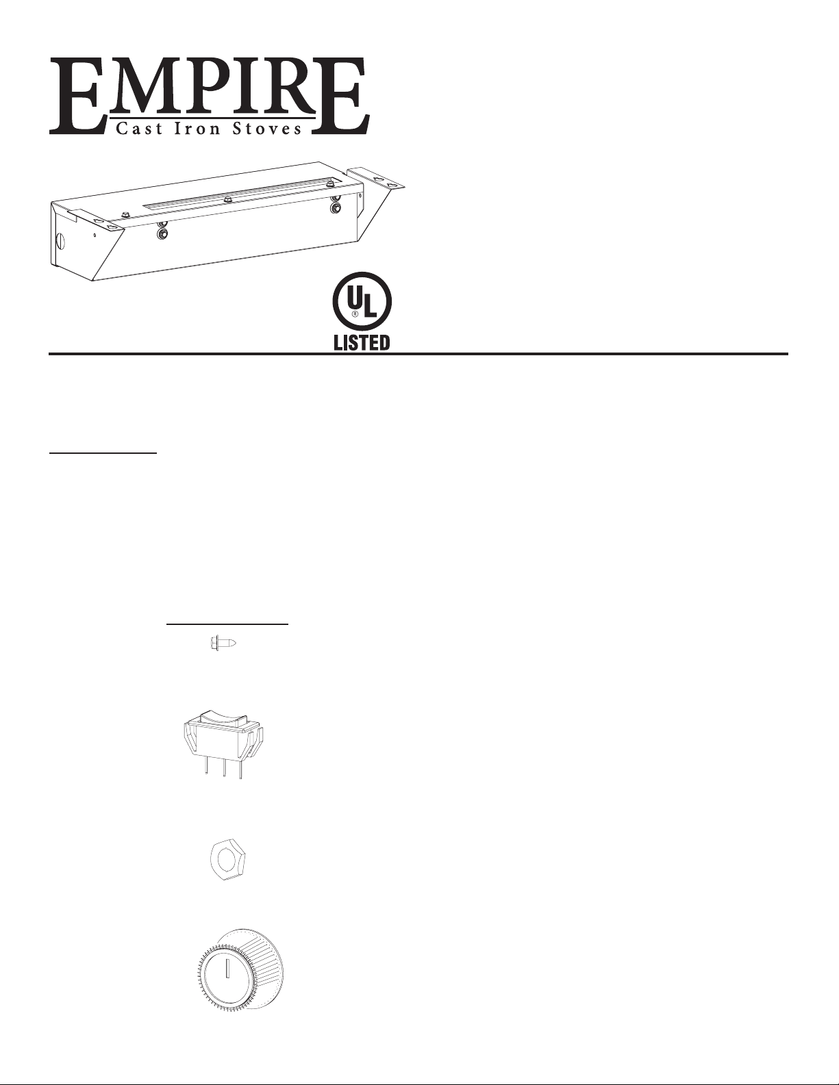
KNOB
GAS-FIRED
CAUTION: Sharp edges, use protective gloves when
installing.
Carton Contents
Blower Assembly
Auto/On/Off Switch
Fan Control Bracket Assembly
Hardware Package
(2) 10 x 1/2” Screw
(1) On/Off/Auto Switch
(1) Rheostat Nut
(1) Knob, Rheostat
Hardware Package
#10x1/2” SCREW
AUTO/ON/OFF SWITCH
NUT
INSTALLATION
INSTRUCTIONS
CAST IRON BLOWER
CIB3-3
FOR USE ON:
EMPIRE CAST IRON STOVES
MODELS:
DVP30CA30(B,F,M,S,W)(N,P)
DVP30CC(30,70)(B,F,M,S,W)(N,P)
VFP30CA30(B,F,M,S,W)(N,P)
VFD30CC(30,70)(B,F,M,S,W)(N,P)
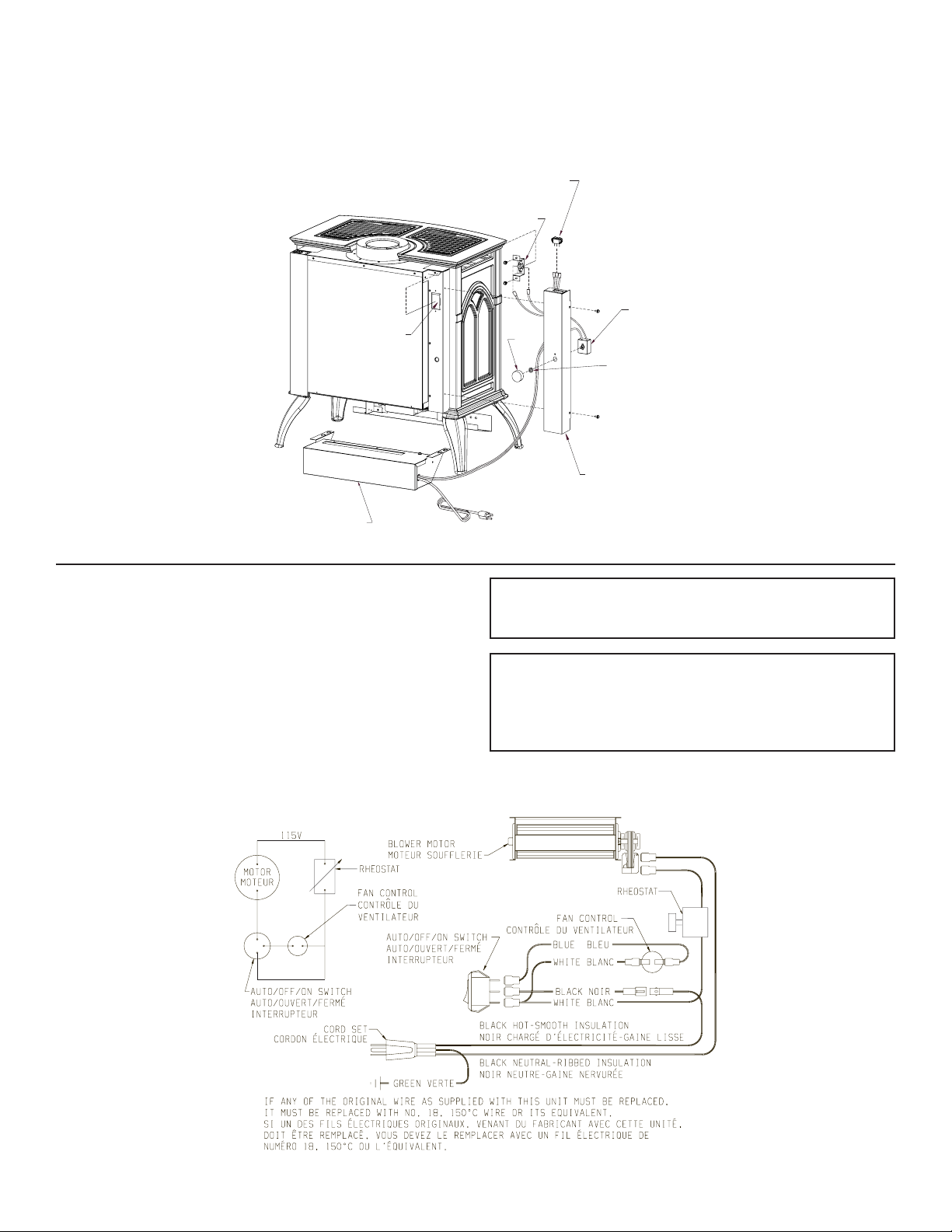
Installing Optional CIB3 Blower
1. Loosen, but do not remove, four hex-head screws located on
the exterior, bottom of the appliance.
2. Position the blower assembly at the rear of the appliance.
The blower assembly has four keyholes for attachment to the
exterior, bottom of the appliance.
3. Place the large diameter holes in the keyholes over and behind
the four hex-head screws that were loosened in Step 1. Push
inward on the blower assembly to lock the keyholes into position
behind the screws. Tighten four hex-head screws to secure
blower assembly to exterior, bottom of the appliance.
4. Remove wire channel-left from appliance by removing two
10 x 1/2" screws on left side of the appliance.
5. Route fan control wires through rectangular notch on wire
channel - left.
6. Attach 1/4" push-on terminal from blue wire on the fan control
to the AUTO (top) tab on the switch.
7. Attach 1/4" push-on terminal from black wire to the OFF (middle)
tab on the switch.
8. Attach 1/4" push-on terminal from white wire on the fan control
to the ON (bottom) tab on the switch.
9. Insert AUTO/OFF/ON switch into rectangular notch on wire
channel - left.
10. Install rheostat through hole in wire channel and align small
tab with small hole.
11. Use an 11/16” wrench to tighten rheostat nut on stationary
12. Push rheostat knob onto knob stem until fully seated.
13. Bend the fan control tab, located on the left side of the back
of the unit, inward toward the unit. See Figure 1. Be sure tab
is bent at least 90 degrees to allow fan control bracket to slide
into slot.
14. Attach fan control with bracket onto rear cover with
two (2) 10 x 1/2" screws provided in hardware package.
15. Route wires from fan control and ON/OFF/REMOTE switch
within wire channel.
16. Attach wire channel with two 10 x 1/2" screws from Step 4.
17. Installation of optional CIB3 blower is completed.
Page 1
Page 2
Fan Control
FAN CONTROL
RHEOSTAT
KNOB
NUT
WIRE CHANNEL - LEFT
FAN CONTROL TAB
The fan control is a non-adjustable automatic type The fan control
will require between 5 and 10 minutes of main burner operation
before the fan control "closes" and activates the blower. The blower
will continue to run between 5 and 10 minutes after the main burner
shuts off, before the fan control "opens" and deactivates the blower.
Model DVP30CA Shown
Cleaning
The blower wheel will collect lint and could require cleaning once
a year. If the air output decreases or the noise level increases, it
indicates a dirty wheel.
Blower Motor
The blower motor does not have oiling holes. Do not attempt to oil
blower motor.
AUTO/OFF/ON SWITCH
BLOWER ASSEMBLY
Figure 1
Wiring
The appliance, when installed, must be electrically grounded in
accordance with local codes or, in the absence of local codes, with
the National Electrical Code, ANSI/NFPA 70 or Canadian Electrical
Code, CSA C22.1, if an external electrical source is utilized. This
appliance is equipped with a three-prong [grounding] plug for
your protection against shock hazard and should be plugged
directly into a properly grounded three-prong receptacle. Do
not cut or remove the grounding prong from this plug. For an
ungrounded receptacle, an adapter, which has two prongs and a
wire for grounding, can be purchased, plugged into the ungrounded
receptacle and its wire connected to the receptacle mounting screws.
With this wire completing the ground, the appliance cord plug can
be plugged into the adapter and be electrically grounded.
(CIB3 ONLY)
CAUTION: Label all wires prior to disconnection when servicing
controls. Wiring errors can cause improper and dangerous
operation. Verify proper operation after servicing.
WARNING:
Unplugging of blower accessory will not stop the heater
from cycling. To shut heater off: Turn temperature dial or
thermostat to lowest setting. Turn knob on gas control to
"OFF," depressing slightly. Do not force.
(CIB3 ONLY)
Figure 2
30724-3-1214Page 2
Page 3

OPTIONAL BLOWER EXPLODED VIEW & PARTS LIST
7
6
8
13
12
9
5
4
11
10
2
3
INDEX NUMBER PART NUMBER DESCRIPTION
1 R-1454 BRASS BUSHING
2 R-1499 RUBBER GROMMET
3 31739 BLOWER HOUSING
4 R-1410 STRAIN RELIEF BUSHING
5 R-9927 BLOWER ASSEMBLY
6 24225 BLOWER COVER
7 R-6159 CORD SET
8 R-10363 WIRE HARNESS
9 R-2503 FAN CONTROL
10 24222 FAN CONTROL BRACKET
11 R-2805 AUTO OFF/ON SWITCH
12 R-4192 RHEOSTAT KNOB
13 18879 RHEOSTAT
1
PARTS LIST
HOW TO ORDER REPAIR PARTS
Parts Not Under Warranty
Parts can be ordered through your Service Person, Dealer, or a Master Parts Distributor. See this page for the Master Parts Distributors list. For best results, the service person or dealer should order parts through the distributor. Parts can be shipped directly to the
service person/dealer.
Warranty Parts
Warranty parts will need a proof of purchase and can be ordered by your Service Person or Dealer. Proof of purchase is required for
warranty parts.
All parts listed in the Parts List have a Part Number. When ordering parts, rst obtain the Model Number and Serial Number from the
name plate on your equipment. Then determine the Part Number (not the Index Number) and the Description of each part from the following illustration and part list. Be sure to give all this information . . .
Appliance Model Number Part Description
Appliance Serial Number Part Number
Type of Gas (Propane or Natural)
Do not order bolts, screws, washers or nuts. They are standard hardware items and can be purchased at any local hardware store.
Shipments contingent upon strikes, res and all causes beyond our control.
30724-3-1214 Page 3
Page 4

Empire Comfort Systems Inc.
918 Freeburg Ave. Belleville, IL 62220
EMPIRE
EMPIRE
Comfort Systems
www.empirecomfort.com
If you have a general question about our products, please e-mail us at
info@empirecomfort.com.
If you have a service or repair question, please contact your dealer.
30724-3-1214Page 4
 Loading...