

Page 1
OWNER’S MANUAL
WWW.EMPIREBATTLETESTED.COM
Page 2

CONTENTS
1. RULES FOR SAFE MARKER HANDLING 1
2. INTRODUCTION AND SPECIFICATIONS 1
3. GETTING STARTED 1
4. FIRING YOUR MARKER 3
5. VELOCITY ADJUSTMENT 3
6. ACCESSORY ADJUSTMENTS 3
7. UNLOADING YOUR MARKER 4
8. REMOVING AIR SUPPLY 4
9. CLEANING MARKER 4
10. STORAGE AND TRANSPORTATION 4
11. DISASSEMBLY / REASSEMBLY 4
12. PARTS LIST & DIAGRAMS 7
WARRANTY (Inside Back Cover)
For manuals and warranty details, go to: paintballsolutions.com
For manuals in other languages, (where applicable), go to: paintballsolutions.c om
©2011 Empire Paintball. The Empire L ogo, and “Battle Tested” are trademarks of
Empire Paintball. All rights reserved. Empire Battle T ested is a brand of KEE A ction
Sports, LLC.
EMPIREBATTLETESTED.COM
Page 3

1. Rules for Safe Marker Handling
IMPORTANT: Never carry your Marker uncased when not on a playing eld. The
non-playing public and law enforcement personnel may not be able to distinguish
between a paintball marker and rearm. For your own safety and to protect the
image of the sport, always carry your Marker in a suitable marker case or in the box
in which it was shipped.
• Treat every marker as if it were loaded.
• Never look down the barrel of a paintball marker.
• Keep your nger OFF the trigger until ready to shoot.
• Never point the marker at anything you don’t wish to shoot.
• Keep the marker on “safe” until ready to shoot.
• Keep the barrel blocking device in/ on the marker’s barrel when not shooting.
• Always remove paintballs and propellant source before disassembly.
• After removing air source, point marker in safe direction and discharge until
marker is degassed.
• Store the marker unloaded and degassed in a secure place.
• Follow warnings listed on the air source for handling and storage.
• Do not shoot at fragile objects such as windows.
• Every person within range must wear eye, face and ear protection designed
specically to stop paintballs and meeting ASTM standard F1776.
• Always measure your marker’s velocity before playing paintball and never shoot at
velocities in excess of 91.44 meters (300 feet-per-second).
2. Introduction and Specications
Congratulations on your selection of the Empire BT-4 Slice paintball marker. Empire
BT-4 Slice markers are made to provide you with many years of reliable performance.
Empire Paintball, Inc. is honored that you have chosen an Empire BT-4 Slice marker as
your marker of choice and hope you enjoy using this high quality product.
Specications
Caliber ............................................................................................................................................. .68
Mechanical Action ..........................................................................................Semi-Automatic
Electronic Grip Action ............................... Semi-Automatic, Ramping and Full-Auto
Powered ..................................................................... CO2 or Compressed Air (HP Output)
Main Body Material.................................................................................................... Aluminum
Empire BT-4 Slice markers come with a removable barrel system. This feature allows the
user to select a barrel that is most suitable for the playing conditions.
3. Getting Started
Safety and Safe marker handling are the most important aspects of paintball
sports. Please practice each of the following steps with an unloaded marker before
attempting to charge your marker with compressed air and paintballs.
Do not install an air cylinder or load paintballs into your Marker until you feel
completely condent with your ability to handle your Marker safely.
Read this entire manual before loading, attaching a propellant
source or in any way attempting to operate any Empire BT-4 Slice
marker.
NOTE: Eye protective devices designed specically for paintball use must be worn by the operator and anyone within range.
©Empire Paintball, Inc.
1
EMPIREBATTLETESTED.COM
Keep your nger out of the trigger guard and away from the trigger; point the muzzle
of the marker in a safe direction at all times. Keep the marker in safety or turned o
until ready to operate.
Always keep your Marker pointed in a safe direction. Always use a barrel plug or
barrel blocking device. Always use paintball specic eye protection which meets or
exceeds ASTM standards in any areas where paintball markers may be discharged.
Remember that the ultimate safety device is you, the operator.
Page 4
Safe Mode
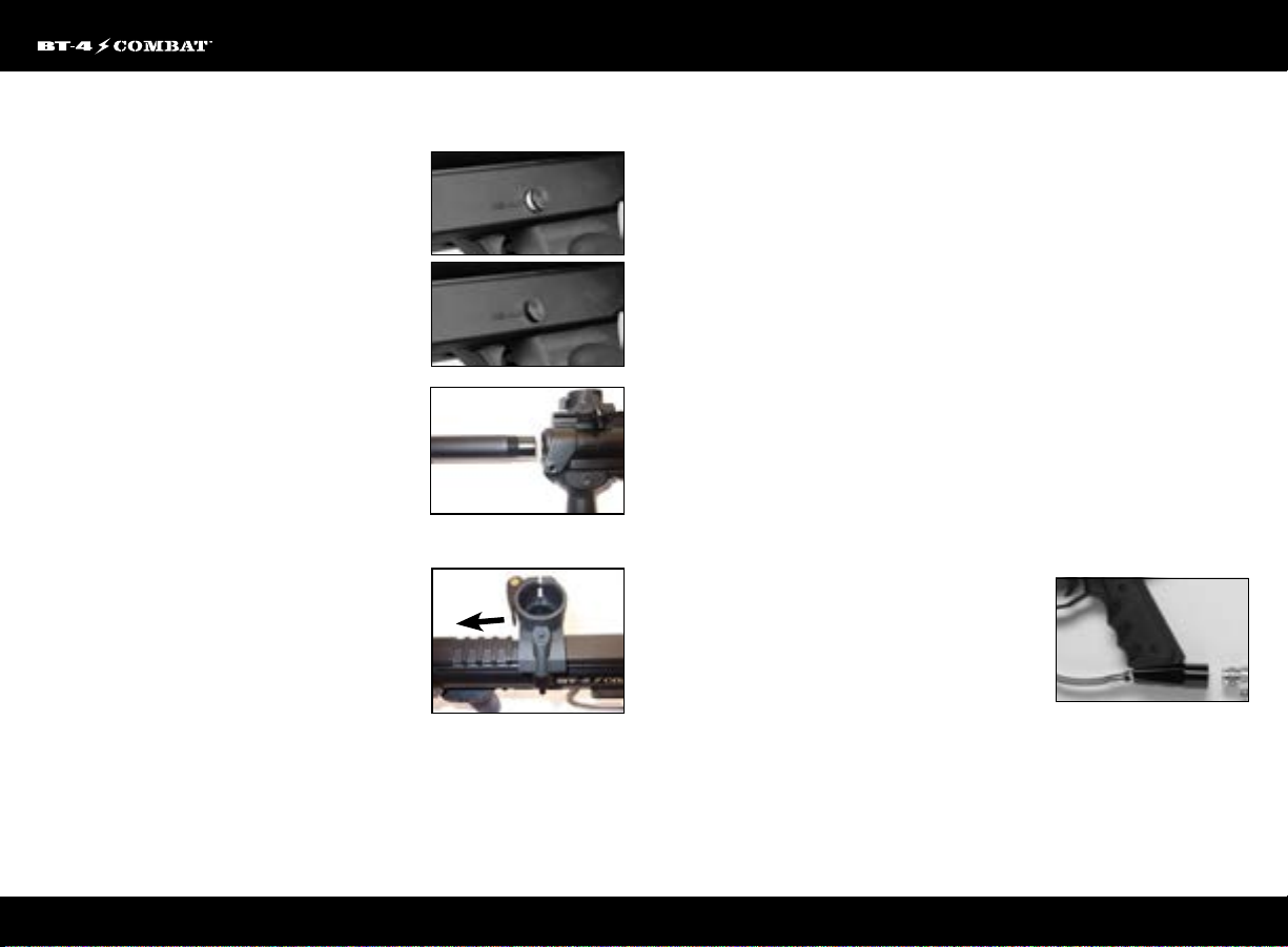
In this manual, you will see the term “SAFE” mode. The
Power should be OFF (Fig. 3.1) on electronic grips, or the
Safety should be set to “SAFE” (red marking on safety will
not be visible) Fig. 3.2. Make sure your marker is set to
“SAFE” mode when indicated to do so.
Barrel Installation
Make sure marker is degassed, hopper removed, no
paintballs in the feed port or breech and the marker is
in “Safe” mode.
1. While pointing marker in a safe direction, place the
threaded end of the barrel into the front opening of
the marker body (Fig. 3.3).
2. Turn the barrel clockwise until it stops (do not over
tighten).
3. Adjust the barrel accessories if necessary.
4. Install a barrel blocking device. This can be a barrel
plug or other such device that prevents the accidental discharge of a paintball.
Feed Elbow and Loader Installation
1. Press and hold the retention button located on the
side of the Slide-Away™ elbow.
2. Slide the elbow onto the front narrow gap of the
picatinny rail. (g. 3.4)
3. Line up the elbow with the feed hole on the right
side receiver.
4. Check that the elbow is locked in place and properly aligned.
Note: Spring-loaded retention button must line up in a gap on the Picatinny rail.
SAFETY OFF
Fig. 3.1
SAFETY ON
Fig. 3.2
Fig. 3.3
Fig. 3.4
Standard Loader
1. To install a loader check the Slide-Away™ elbow and loader to make sure they
are free from debris and obstructions.
2. Position Slide-Away™ elbow onto your marker’s receiver.
3. Release the Clamp Arm to allow the loader to slide into the top of the elbow.
4. Press the loader into the opening of the Elbow until it stops.
5. Align the loader so that the lid is pointing to the rear and the loader is parallel
with the marker.
6. Clamp the loader in place by closing the clamping arm. Do not over tighten the
loader.
Note: It might be necessary to adjust the clamping feed elbow screw to t your loader. Using a 3/32" hex wrench, turn the
screw clockwise to increase the clamping force or counter-clockwise to decrease the clamping force.
Air Cylinder Installation
Consult the place where you purchased your Empire BT-4 Slice Marker, or a recognized
and competent air smith, for instruction in the safe handling of compressed-air
cylinders before purchasing or connecting one to your Empire BT-4 Slice Marker.
Before Pressurizing Your Marker
1. Check to make sure that you and anyone within range are wearing eye protection
designed specically for paintball.
2. Double check that all screws are tightened and no parts are loose before installing
your tank.
3. Ensure you have a barrel plug, barrel sock or other specically designed barrelblocking device in place.
4. Make sure there are no paintballs in the marker.
5. Set marker to “SAFE” mode.
Pressurizing your Marker
1. While pointing the marker in a safe direction,
cock the marker by pulling the T-handle, located
in the rear of the body, back until it clicks and stops.
2. Release the cocking handle, the marker is
now cocked.
3. Locate the Air Source Adapter (ASA) located at the base of the pistol grip.
4. Position the Empire BT marker so that the ASA is pointed upwards while keeping
the muzzle of the marker pointed in a safe direction.
5. Insert the threaded cylinder valve end into the ASA.
6. Without forcing the cylinder, twist the cylinder clockwise and allow the threads
to draw the cylinder into the marker until it stops. Your marker is now charged.
2
EMPIREBATTLETESTED.COM
Page 5
Notes:
• Remember compressed air, nitrogen systems and CO2 cylinders can be extremely dangerous if misused or improperly
handled. Use only cylinders meeting D.O.T. or regionally dened specications.
• Never disassemble your tank or tank regulator. Only a qualied and trained technician should perform work on your tank
and tank regulator.
• Never add any lubricants or greases into the ll adapter on your tank regulator.
Loading Paintballs
Empire BT markers use .68 caliber, water-soluble
SAFETY OFF
paintballs, readily available at paintball pro-shops,
commercial playing elds and many sporting goods
stores. The paintballs are fed from the loader through
the feed elbow into the breech of the marker.
1. Make sure the marker is set to SAFE mode.
SAFETY ON
2. Put on eye protection designed specically for
paintball and make sure that anyone within range of
the marker does the same.
3. Load quality .68 caliber paintballs into your loader/hopper (leave some room for
paintballs to move about inside the loader).
4. Firing Your Marker
Warning: Always keep your Marker pointed in a safe direction! Everyone within
ring range should always use paintball approved eye and face protection in the
presence of live paintball markers. Make sure the Marker is set to “SAFE” mode,
before following the steps below.
Standard Mechanical Frame
• Place the empty loader onto the marker.
• Be sure that it is securely mounted in place.
• Cock the marker, by pulling back on the T-handle.
• Apply the air cylinder, pressurizing the marker.
• Put the paintballs into the loader.
• Remove the barrel plug, sock or barrel-blocking device.
• Aim the BT-4 Slice marker in a safe direction.
• Set the Safety to the “Fire” position.
• Aim the Marker at the target.
• Place your nger on the trigger.
• Pull the trigger with a smooth squeezing motion.
5. Velocity Adjustment
Always check the velocity of the marker prior to playing
paintball. Dierent playing elds may have dierent
maximum velocity limits. At no time should you shoot
at velocities above 300 feet-per- second.
Fig. 3.4
Fig. 3.3
1. Put on an eye protective device designed specically for paintball and make sure
that anyone within range of the Empire BT-4 Slice marker does the same.
2. While pointing the marker in a safe direction, remove the barrel blocking device.
3. Point the Empire BT-4 Slice marker over a chronograph that will measure the velocity
of the paintballs discharged by the marker.
4. Set the marker to “FIRE” mode.
5. Pull the trigger and check the reading on the chronograph.
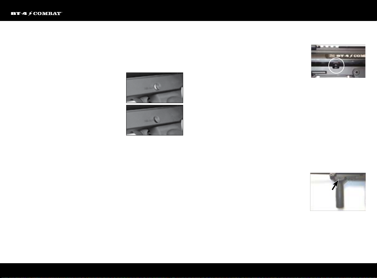
6. Locate the velocity adjuster screw on the left side of the marker.
7. Using a 5/32" hex key, turn the screw inward or clockwise to reduce the velocity, and
outward or counterclockwise to increase the velocity of the paintballs discharged
from the marker (Fig. 3.5).
DO NOT REMOVE THE VELOCITY ADJUSTMENT SCREW.
6. Accessory Adjustments
Vertical Foregrip Adjustment
1. Locate the bolt that secures the foregrip to the
body (Fig. 3.6)
2. Unscrew the bolt using a 5/32” Allen wrench and
remove it completely from the foregrip.
3. Once the bolt is free, the foregrip can be slid into a
new position on the Picatinny
rail, or removed altogether.
4. If changing rail position, be sure that the bolt hole lines up with a gap in
the rail system
5. Once in the desired position, place the bolt back through the foregrip, ensuring the
nut on the backside of the grip is not pushed out.
6. Tighten the bolt with the 5/32” Allen wrench, making sure not to over-tighten.
Fig. 3.6
3
EMPIREBATTLETESTED.COM
Page 6

7. Unloading Your Marker
1. Put on an eye protective device designed specically for paintball and make sure
that anyone within range of the Empire BT-4 Slice Marker does the same.
2. Make sure the barrel blocking device is properly installed and the marker is set to
“safe” mode.
3. Loosen the loader clamping screw or release clamping arm.
4. While holding the paintball hopper in place, invert the marker so that the hopper
is below the Empire BT-4 Slice marker.
5. Remove the loader and all paintballs.
6. While pointing the Empire BT-4 Slice marker in a safe direction, remove the barrel
blocking device.
7. Keep the Empire BT-4 Slice marker pointed in a safe direction and pull the trigger
several times to insure there are no balls remaining in the chamber or the barrel.
8. Properly re-install the barrel blocking device and set the marker is set to “SAFE”
mode.
8. Removing Air Cylinder
1. Make sure the barrel blocking device is properly installed and the Empire BT-4
Slice marker is set to “SAFE” mode.
2. Point the Empire BT-4 Slice marker in a safe direction and turn the cylinder counter
clockwise about 3/4 of a turn. This allows the cylinder valve to close without
damaging the cylinder o-ring.
3. While pointing the Empire BT-4 Slice marker in a safe direction, disengage the
safety (set to “re”).
4. Keeping the BT marker pointed in a safe direction, pull the trigger until the
remaining CO2 or air is expelled and it fails to re-cock.
5. Unscrew the cylinder from the Empire BT-4 Slice marker.
6. The marker is now ready to be cleaned or put away for future use.
9. Cleaning Marker
Once your Empire BT-4 Slice Marker is unloaded and the air cylinder is removed,
you can use a damp cloth to wipe o paint, oil, dirt and debris. You can also use
warm water to rinse the marker clean. Once your marker is clean and dry you can
re-oil using a light, premium marker oil. (Note: Petroleum based and aerosol products
can damage your markers o-rings. DO NOT USE ANY PETROLEUM BASED OR
AEROSOL PRODUCTS ON YOUR MARKER. To access the rear bolt and linkage
arm you must remove the left receiver half. (See the disassembly section.)
10. Storage and Transportation
When you are nished using your Empire BT-4 Slice marker it is important that you
prepare it for storage. This will not only serve to increase the life of the marker, but
will assure optimum performance on your next outing.
• The Empire BT-4 Slice marker must be clear of all paint and propellant when not
being used.
• Be sure to have marker in “SAFE MODE” when not in use.
• Make sure barrel blocking devise is in place.
• Store Empire BT-4 Slice marker and propellant in cool dry place.
• Keep your Empire BT-4 Slice marker away from children without proper supervision.
• Your Empire BT-4 Slice marker must be free of all paint and not attached to a
propellant source while being transported to and from the playing eld.
• Observe and obey all local, state and federal laws concerning the transportation
of paintball markers. For information concerning any of the laws in your area,
contact your local law enforcement.
• Always store the marker in a secure location when not in use so as to prevent
access by unauthorized persons.
IMPORTANT: Never carry your Empire BT-4 Slice Marker uncased when not on a
playing eld. The non-playing public and law enforcement personnel may not be
able to distinguish between a paintball marker and rearm. For your own safety and
to protect the image of the sport, always carry your Empire BT-4 Slice Marker in a
suitable marker case or in the box in which it was shipped.
11. Disassembly/Reassembly
CAUTION: Before attempting to perform any maintenance operations, make sure
that all paintballs and propellant sources have been removed from the marker. Install
a barrel blocking device, Marker must be unloaded, degassed and un-cocked before
any disassembly or maintenance. Follow unloading and removing air supply steps.
4
EMPIREBATTLETESTED.COM
Page 7
Disassembly/Reassembly (continued)
Disassembly Tips
• Make sure you have a clean area to work on your marker.
• When separating the Shell for the first time, do so carefully, so you do not lose any parts.
• Visit PaintballSolutions.com for additional information.
Barrel Removal
Turn the barrel counter clockwise to remove it from the
marker. Keep your barrel clean for best results.
Slide-Away™ Elbow Removal
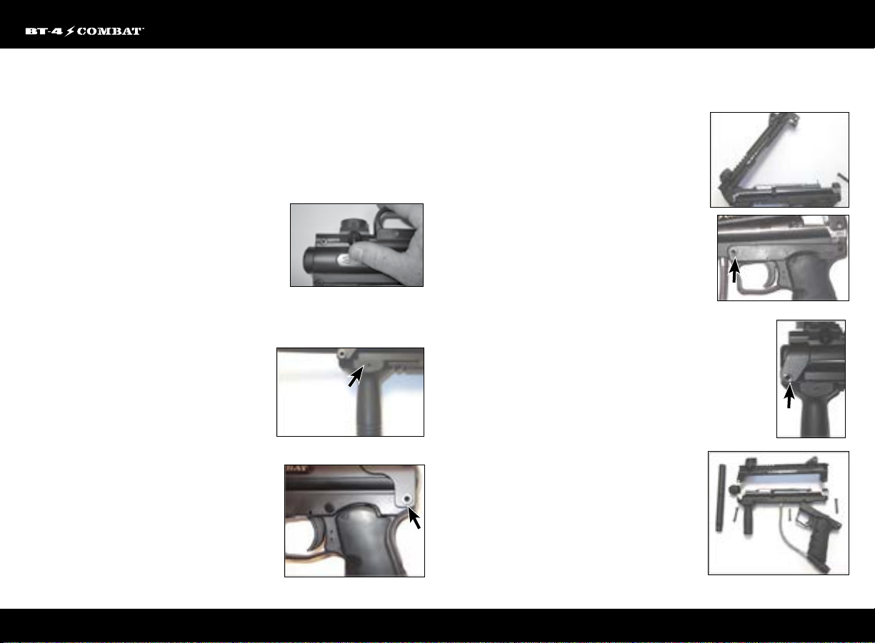
1. Press and hold the retention button located on the
name plate side of the Slide-Away™ Elbow (Fig. 3.7).
2. Slide the Elbow toward the front narrow gap of the marker and remove.
3. Reverse process to replace Slide-Away™ Elbow.
Front Foregrip Removal
1. Locate the bolt that secures the foregrip to the
body (Fig. 3.8).
2. Unscrew the bolt using a 5/32” Allen wrench
and remove it completely from the foregrip.
3. Once the bolt is free, the foregrip can be slid o
the Picatinny rail.
4. Reverse the process to install the foregrip.
Splitting the Body
1. Locate the Rear Trigger Frame Pin (Fig. 3.9)
2. Push the pin through the body and remove
completely from the marker shell
3. Pull the upper and lower shells apart, making
sure the barrel plug does not impede the split
4. Once the shells are apart, you can now access
the internals for maintenance and repair (Fig. 4.0).
Fig. 3.7
Fig. 3.8
Fig. 3.9
Note: It may not be necessary to loosen the 3 screws on the Delta rear sight;
see if it slides o rst.
Trigger Frame Removal
1. Remove the Rear Trigger Frame Pin as
described in the Splitting the Body section
2. Locate the second Spring Pin on the
Trigger Frame (Fig. 4.1).
3. Push the pin through the marker body
and then pull it free of the Trigger Frame
4. Lower the Trigger Frame from
the Receiver
Note: The frame will still attached to the receiver by the steel braided hose. It is
recommended that you do not remove the hose from the valve or the tank adapter.
Receiver (Body) Separation
Make sure the marker is in the un-cocked (forward position) before
taking body apart.
1. Remove the Rear Trigger Frame pin as described
previously in the Splitting the Body section
2. Remove the Front Trigger Frame pin as described
previously in the Trigger Frame
Removal section
3. Locate the Front Body Pin (Fig. 4.2)
4. Push the pin through the marker and then pull it
free of the Body
5. Lift the upper half of the Body free from the
lower half
6. All components are now accessible for
maintenance or repair (Fig. 4.3)
Note: The end cap/stock will be under some spring tension and may spring out
when the top name plate receiver is lifted o.
Note: The retention screw located below the bolt handle slot is longer than
the rest.
Fig. 4.0
Fig. 4.1
Fig. 4.2
Fig. 4.3
5
EMPIREBATTLETESTED.COM
Page 8
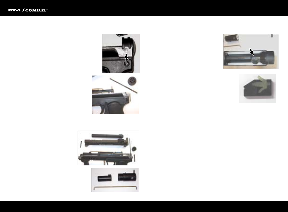
Removing End Cap/Stock, Spring Guide,
Bumper and Spring
1. Remove the Rear Trigger Frame pin as described
previously in the Splitting the Body section
2. Split the upper shell from the lower, making sure the
barrel plug stays seated to not interfere with the upper
shell pivoting
3. Locate the pin that holds the End Plug in
place (Fig. 4.4)
4. Push the pin out of the lower Body, making sure
that you do not try to push the knurled end
5. Once the End Cap Pin is removed, the End Cap
can be taken o the Body, being careful not to lose
the Spring and Spring Guide (Fig. 4.5).
Removing Barrel Adapter, Front Bolt,
Rear Cocking Bolt and Linkage Arm
1. Split the Upper and Lower Receiver
ass described previously in this section
2. This now allows access to the Front
Bolt, Rear Cocking Bolt and Linkage
Arm (Fig. 4.6)
3. Remove the Linkage arm
4. Remove the Barrel Adapter from the
Lower Receiver/Body
5. Slide the Front bolt forward along the
power tube until free and remove
6. Slide the Rear bolt rearward and
remove (Fig. 4.7)
Fig. 4.6
Fig. 4.7
Fig. 4.5
Fig. 4.4
Removing Ball Detent
1. Remove the Front Bolt and Barrel Adapter
as described previously
2. Locate the Detent Shell (Fig. 4.8)
3. Remove the Detent Shell and Detent from
the Lower Receiver
4. Once free of the Receiver, the Detent can
be removed from the Detent Shell (Fig. 4.9)
Fig. 4.8
Reassembly
To reassemble the marker, reverse the Disassembly
instructions starting with the barrel adapter, ball detent
and front bolt removal. While reassembling the marker,
you should oil all O-rings and sliding parts. All parts and
o-rings returned to the marker should be free of debris
and visual nicks and scratches which can alter the performance of the marker. All
screws returned to the marker must be tightened so there is no chance of them
vibrating loose.
Fig. 4.9
6
EMPIREBATTLETESTED.COM
Page 9
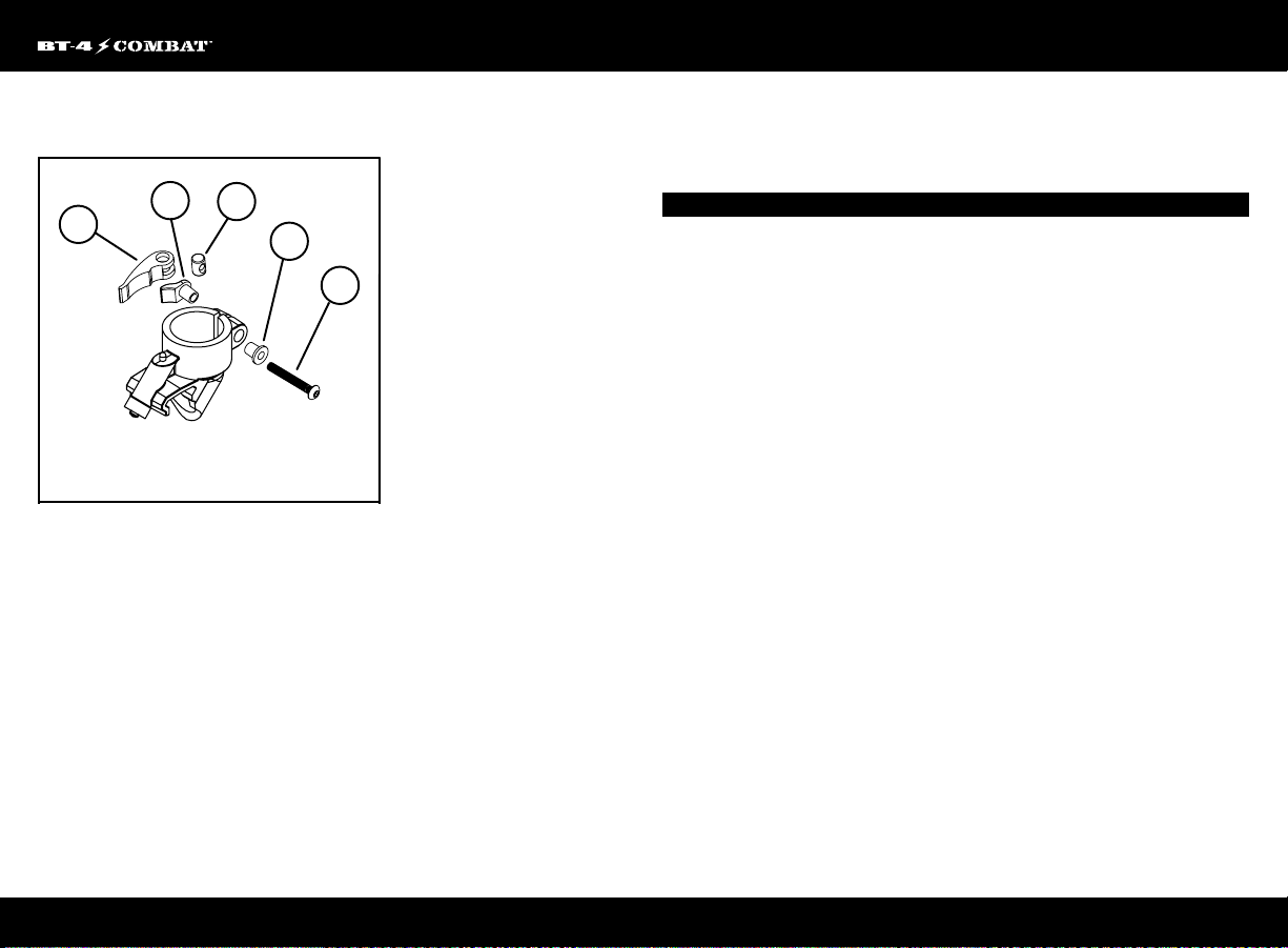
Empire BT Feednecks Parts List
4
3
2
CLAMPING FEEDNECK
PART #17757
SCHEMATIC# ...........................................................................................................................DESCRIPTION SKU#
5
1
1 Clamping Feed Elbow Screw ................................................................................................17759
2 Clamping Feed Elbow Lever..................................................................................................17760
3 Clamping Feed Elbow Collar .................................................................................................17761
4 Clamping Feed Elbow Seat ....................................................................................................17762
5 Clamping Feed Elbow Spacer ..............................................................................................17763
Clamping Feed Elbow (complete) .....................................................................................17757
7
EMPIREBATTLETESTED.COM
Page 10
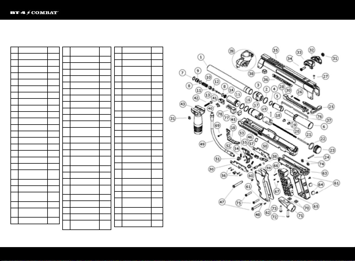
Empire BT-4 Slice Combat™ Parts List
# PART DESCRIPTION SKU
1 BARREL 19390
2 BARREL O-RING 19452
3 BARREL ADAPTER 71900
4 FRONT BOLT O-RING 19424
5 FRONT BOLT 19409
6 POWER TUBE 19384
7 VALVE SNAP RING 19442
8 INTERNAL VALVE O-RING 19425
9 FRONT VALVE SEAT 19393
10 VALVE SPRING 19444
11 PLUNGER CUP 19394
12 CUP SEAL 19387
13 VALVE STEM 99126
14 REAR VALVE SEAT 19395
15 VALVE BODY 19392
16 VALVE AND BOLT O-RING 19426
17 REAR BOLT 71902
18 BOLT PLUG 71903
DOWEL PIN 3MM DIA
19
X 18MM
20 DRIVE SPRING 19447
21 DRIVE SPRING PIN 19448
SHOCK ABSORBER
22
O-RING
23 END CAP 71921 71921
DOWEL PIN 3MM DIA X
24
28.5MM
25 HANDLE COCKING 71918
71928
19427
71922
SPRING EXT .1875OD X
26
1.250OL
27 T-HANDLE SCREW 71940
28 COVER HANDLE SPRING 71916
29 VALVE LOCK SCREW 19416
30 PIN SPRING 71920
31 NUT RECEIVER 19415
32 SIGHT REAR RH 19431
33 SIGHT REAR LH 19432
34 LONG RECEIVER BOLT 19413
35 BODY SHELL TOP 71914
36 LOGO 71919
37 LINKAGE ARM 19410
SUPPORT BARREL
38
ADAPTER TOP
39 FEED ELBOW 17757
40 DETENT 19386
41 DETENT SHELL 71917
SCREW SHCS 10-32
42
X 1.250
43 FRONT GRIP 71907
45 BODY SHELL BOTTOM 71915
46 VELOCITY SCREW 19418
PIN SPRING FRONT
47
PIVOT
48 SPRING PIN 71912
49 GAS LINE 19435
50 TRIGGER PLATE 19402
51 TRIGGER PLATE SPACER 19404
TRIGGER RETURN
52
SPRING
71927
71924
71929
71904
19446
53 TRIGGER 71909
54 TRIGGER PIN 19438
55 TRIGGER SLIDE SPRING 19451
TRIGGER PLATE
56
DOWEL PIN
57 TRIGGER SLIDE 19408
58 SEAR 19405
59 SAFETY w/ O-Ring 71910
60 SEAR SPRING 19449
GRIP SCREW THST PHL
61
#4 X 0.3125
62 GRIP 19429
63 GRIP FRAME v2 71901
64 GRIP FRAME PLUG 71923
65 GRIP SUPPORT 71911
66 GRIP SUPPORT SCREW 7 1925
67 GRIP SUPPORT SCREW 71913
68 TRIGGER GUARD 71906
69 TRIGGER GUARD SCREW 19443
70 ASA NUTS 19423
AIR SOURCE ADAPTER
71
(ASA)
72 LONG ASA SCREW 19439
73 SHORT ASA SCREW 19440
74 GRIP FRAME NUT 19441
GRIP FRAME SCREW
75
SHCS 10-32 X 1 LOW PRO
76 T-HANDLE NUT 71941
77 FILL BLOCK REAR 71 943
78 FILL BLOCK FRONT 71944
19436
19430
17044
71942
8
EMPIREBATTLETESTED.COM
Page 11
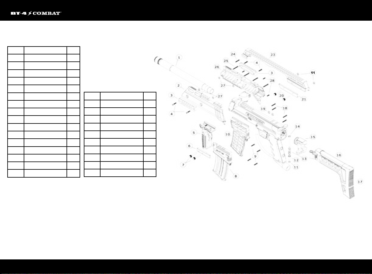
G36 Diagram Labelled.pdf 1 6/4/14 10:34 AM
Empire G36 Slice Combat™ Parts List
Diagram # Part Description SKU
1 G36 barrel tube 71945
2 Shroud left 71969
3 Picatinny Side Rail 17709
4 Screw No.6-32*5/8"L 71963
5 Empire BT Folding Foregrip 52087
6 G36 Magazine clip 71947
7 G36 Clip screw 71946
8 G36 Magazine Left 71948
9 Screw No.3*16mm 71962
10 G36 Magazine right 71949
11 Nut No.8-32 8.7 71960
12 G36 Stock Sleeve 71954
13 G36 Stock Spring 71955
14 G36 Stock Screw 71953
15 G36 Stock Adaptor 71951
16 G36 Stock 71950
17 G36 Stock Cushion 71952
18 Screw ST 3.2*20mm 71966
19 Nut No.10-32 71959
20 G36 Top Rail Screw 71958
21 G36 Top Rail Clip 71957
23 G36 Top Rail 71956
24 Screw ST3.0*20mm 71964
25 Screw ST3.0*25mm 71965
26 Shroud right 71969
27 NutNo.6-32* 6.35mm 71961
28 ScrewNo.3*10mm 71967
9
EMPIREBATTLETESTED.COM
Page 12
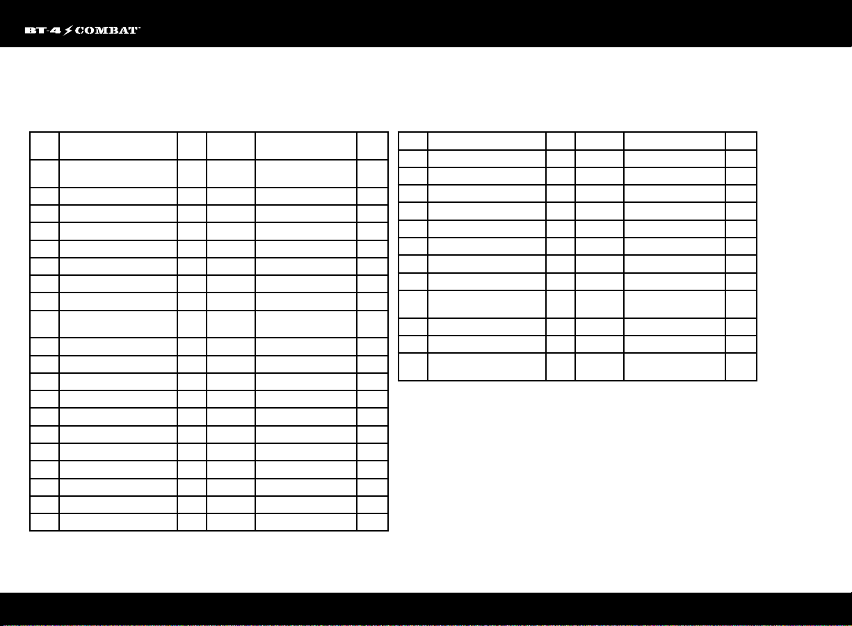
Empire G36 Elite Slice Combat™ Parts List
Dia-
Part Description SKU Diagram # Part Description SKU
gram #
APEX
PARTS
1 APEX HOUSING TUBE 11502 31a Rail Locking Screw Long TM Marker 38445
2 APEX BODY INSERT TOP 11500 31b Rail Locking Screw Short BT4 Marker 38432
3 APEX ADJUSTER 11505 32 Rail Locking Thumb Nut 38433
4 APEX DEFLECTOR 11503 33 Picitinny Locking Rail 38395
5 O-RING BUNA-N 70 DUR -021 (.926 ID) 11506 34a TM-15 Adapter Plate 17852
6 APEX BODY INSERT BOTTOM 11501 34b TM-7 Adapter plate 38449
7 APEX WIRE SPRING 11504 35 Ball Sleeve 38421
E-GRIP
PARTS
8 Led Screen & On/Off Switch Sticker (2pcs) 20187 37 Anti Jam Assembly 38427
9 ASA Nut 19423 38 Anti Jam Spring 38800
10 Short Receiver Bolt 19414 39 Drive Cone Spring 38814
11 Electronic Sear Spring 20180 40 Drive Carrier 38430
12 Electronic Sear 20178 41 Battery Cover Washer 38436
13 Sear Housing 71942 42 Battery Cover Screw 38435
14 Sear Housing Dowel Pin .125 Dia X .500 72518 43 Battery Cover Assembly 38420
15 Electronic Sear Lock Pin 71941 44 Drive Shaft Screw 38822
16 Dowel Pin .125 Dia X 1.125 20177 45 TM Circuit Board 38448
17 Trigger Switch Pin - Dowel 2mm Dia X 1.125 20183 46 On/Off Button Pad 38442
18 Grip Frame 71901 47 Spring Housing 38429
RIP CLIP PARTS
36 Locking Rail Nut 38396
19 Trigger Guard Grip Screw 19443 48 Battery Cover Nut 38426
20 Double Trigger Alu 20175 49 Rip-Clip RF Body 38397
21 Trigger Set Screw 8-32 X .250 Flat Point 20176 50 Drive Shaft 38428
22 Grip Screw THST PHL #4 X 0.3125 19430 51 Sprocket Gear 38830
23 Double Trigger Guard 71940 52 Motor w/ Harness 38423
24 Grip 71908 53 Drive Belt 38820
25 Circuit Board 19378 54 Bottom Cover 38416
26 Circuit Board Screw PHST PHL 2-32 X .188 20184 55 Rip Drive 2 Wheel 31023
27 Battery Harness 20168 56 Bottom Cover Screw 38425
28 Solenoid Support & Screw PHST PHL
M2.2x13mm (2pc)
29 Solenoid Assy 17046 58 Bearing 38803
30 Microswitch Assy 20182 59 Pulley Gear Pin 38828
Not
200 Round Hopper 38604 60 E-Clip 38823
Shown
20188 57 Pulley Gear 38837
10
EMPIREBATTLETESTED.COM
Page 13
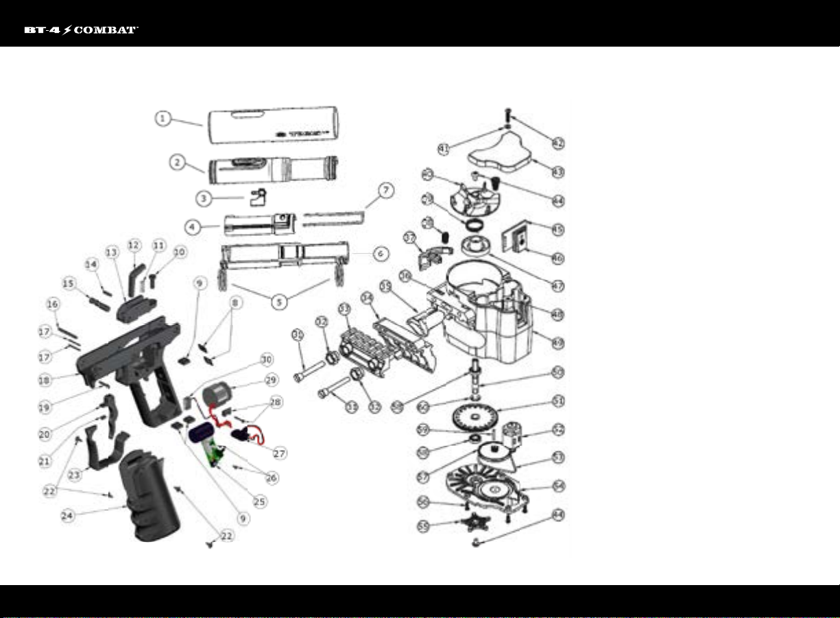
Empire G36 Elite Slice Combat™ Part Diagram
11
EMPIREBATTLETESTED.COM
Page 14

Warranty Information
LIMITED LIFETIME WARRANTY INFORMATION
(ORIGINAL PURCHASE RECEIPT REQUIRED)
Empire BT Paintball warrants that this product is free from defects in materials and
workmanship for as long as it is owned by the original purchaser, subject to the terms
and conditions set forth below. Empire BT Paintball will repair or replace with the
same or equivalent model, without charge, any of its products that have failed in
normal use because of a defect in material or workmanship.
Empire BTPaintball is dedicated to providing you with products of the highest quality
and the industry’s best product support available for satisfactory play.
Purchaser should register product to activate warranty. Register your product by:
1. Online at www.paintballsolutions.com
2. Complete the product registration card (if applicable) and mail along with a copy
of your receipt to Paintball Solutions, 11723 Lime Kiln Rd., Neosho, MO 64850.
WHAT THIS WARRANTY DOES NOT COVER
This warranty does not cover problems resulting from abuse, the unauthorized
modication or alteration of our product, problems resulting from the addition of
aftermarket products and scratches or minor supercial imperfections. Due to the
nature of paintball products it is important that the product be maintained by the
user as indicated in the product manual to remain in good operating condition.
Your Limited Lifetime Warranty will be void if you fail to maintain the product as
recommended in the product instruction manual. In addition, certain parts of a
product may be subject to wear through regular usage. Replacement and repair of
such parts is the responsibility of the user throughout the life of the product. These
parts are not covered under the Limited Warranty. Examples of this type of part
include (but are not limited to) goggle lens, straps, O-ring seals, cup seals, springs,
ball detents, batteries, hoses, drive belts, gears and any part of a product subject to
continuous impact from paintballs. Hydrotesting of air cylinders is not covered under
this warranty.
damages. This warranty is the sole written warranty on Empire’s product and limits
any implied warranty to the period that the product is owned by the original purchaser.
Some states, provinces and nations do not allow the limitation of implied warranties
or of incidental or consequential damages, so the above limitations or exclusions may
not apply to you. This warranty gives you specic legal rights and you may also have
other rights which vary from state to state, province to province, nation to nation.
If you should encounter any problems with your product and you have added
aftermarket parts on your product, please test it with the original stock parts before
sending it in. Always unload and remove air supply before shipping markers. Do
not ship your air supply tank if it is not completely empty. Shipping a pressurized
air supply tank is unsafe and unlawful. Remove all batteries from products prior to
shipping.
This Limited Warranty gives you specic legal rights, and you may also have other
rights which vary from state to state. Some states do not allow the exclusion of
incidental or consequential damages.
For warranty parts, service or information in the U.S., contact Paintball Solutions:
www.paintballsolutions.com • E-mail: [email protected] • Phone: 1-800-220-3222
PATENT(S): See www.paintballsolutions.com/patents © 2011-2012 KEE Action Sports. All rights
reserved. This KEE Action Sports product is protected by one or more United States patents. KEE Action
Sports Trademarks, Designs and Copyrights are protected by one or more United States patents and
International Law. For more information contact KEE Action Sports at [email protected]
In Canada, contact:
Paintball Solutions
98 Bessemer Ct.
Unit 4
London, ON N6E 1K7
1-866-685-0030
The Limited Lifetime Warranty also does not cover incidental or consequential
12
EMPIREBATTLETESTED.COM
Page 15
13
EMPIREBATTLETESTED.COM
Page 16
14
EMPIRE BATTLE TESTED PAINTBALL
11723 Lime Kiln Rd., Neosho, MO 64850
www.empirepaintball.com
 Loading...