

Empire DVCP(32, 36, 42)BP30(N, P)-3DVCP(32 Installation Instructions Manual
INSTALLATION INSTRUCTIONS
INSTALLER:
Leave this manual with the appliance.
CONSUMER:
Retain this manual for future reference.
WARNING
FIRE OR EXPLOSION HAZARD
Failure to follow safety warnings exactly
could result in serious injury, death or
property damage.
— Donotstoreorusegasolineorotheram-
mable vapors and liquids in the vicinity of
this or any other appliance.
— WHAT TO DO IF YOU SMELL GAS
• Donottrytolightanyappliance.
• Donottouchanyelectricalswitch;do
not use any phone in your building.
• Leavethebuildingimmediately.
• Immediately call your gas supplier
from a neighbor’s phone. Follow the
gas supplier’s instructions.
• Ifyoucannotreachyourgassupplier,
calltheredepartment.
— Installation and service must be per-
formed by a qualied installer, service
agency or the gas supplier.
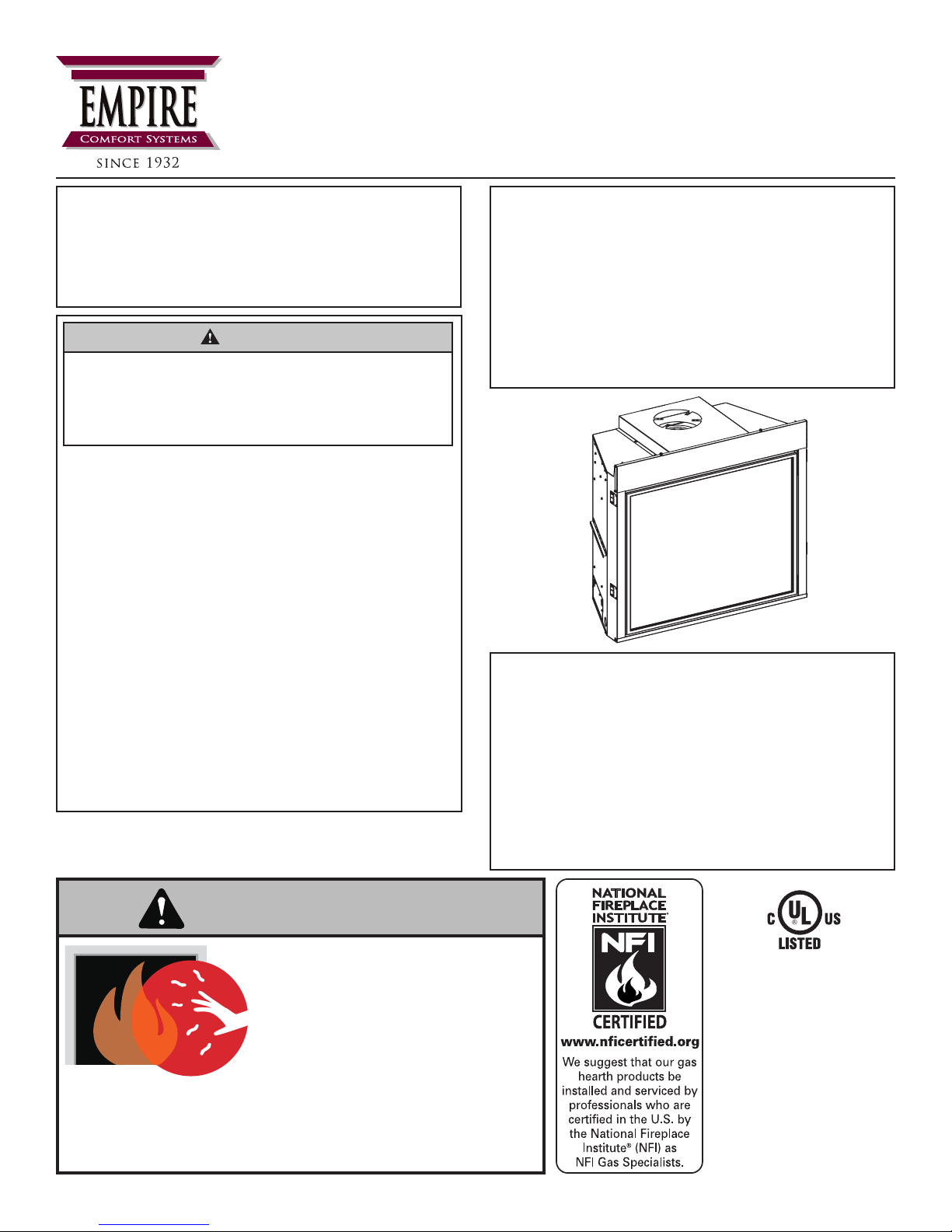
DIRECT VENT
ZERO CLEARANCE GAS
FIREPLACE HEATER SERIES
MILLIVOLT (MV)
DVCP(32,36,42)BP30(N,P)-3
INTERMITTENT PILOT (IP)
DVCP(32,36,42)BP70(N,P)-3
This appliance may be installed in
an aftermarket, permanently located,
manufactured home (USA only) or mobile
home, where not prohibited by state or
local codes.
This appliance is only for use with the type
of gas indicated on the rating plate. This
appliance is not convertible for use with
othergases,unlessacertiedkitisused.
GAS-FIRED
WARNING
HOT GLASS
CAUSE BURNS.
DO NOT TOUCH
UNTIL COOLED.
NEVER
A barrier designed to reduce the risk of burns from the
hot viewing glass is provided with this appliance and shall
be installed for the protection of children and other at-risk
individuals.
ALLOW CHILDREN
TO TOUCH GLASS.
WILL
GLASS
UL FILE NO. MH30033
This replace is design
certied in accordance
with American National
Standard/CSA Standard
ANSI Z21.88/CSA 2.33
and by Underwriters
Laboratories as a Direct
Vent Gas Fireplace
Heater and shall be
installed according to
these instructions.
Page 1

TABLE OF CONTENTS
SECTION PAGE
ATTENTION INSTALLER ..............................................................................................................3
BEFORE YOU START ................................................................................................................ 4-5
CARTON CONTENTS ................................................................................................................... 6
INTRODUCTION ........................................................................................................................... 7
HOMEOWNER REFERENCE INFORMATION ............................................................................. 7
SPECIFICATIONS ......................................................................................................................... 8
ACCESSORIES ............................................................................................................................. 9
FIREPLACE DIMENSIONS ......................................................................................................... 10
FBB10 BLOWER KIT INSTALLATION (OPTIONAL) .............................................................. 11-13
CLEARANCES ............................................................................................................................14
TERMINATION CLEARANCES ................................................................................................... 15
VENT TERMINAL CLEARANCES ............................................................................................... 16
GAS SUPPLY .............................................................................................................................. 17
SAFETY INFORMATION FOR USERS OF LP GAS ................................................................... 18
LOCATING FIREPLACE .............................................................................................................. 19
JUNCTION BOX WIRING INSTALLATION INSTRUCTIONS ......................................................19
MILLIVOLT STANDING PILOT WIRING DIAGRAM .................................................................... 20
IPI ELECTRONIC SYSTEM WIRING DIAGRAM ........................................................................ 21
INSTALLATION .......................................................................................................................22-25
VENT FRAMING .....................................................................................................................26-27
VENT SYSTEM IDENTIFICATION .............................................................................................. 28
SPECIAL VENT SYSTEMS ......................................................................................................... 28
VENTING FIREPLACE - TOP ................................................................................................ 29-32
EXAMPLES - TOP VENT RUN .................................................................................................... 33
HORIZONTAL TERMINATION .....................................................................................................34
VERTICAL TERMINATION .....................................................................................................35-36
DVVK-4F FLEX VENT INSTRUCTIONS ................................................................................37-38
MILLIVOLT STANDING PILOT LIGHTING INSTRUCTIONS ...................................................... 39
MILLIVOLT OPERATING INSTRUCTIONS ................................................................................. 40
MILLIVOLT STANDING PILOT TROUBLESHOOTING ............................................................... 41
INTERMITTENT PILOT LIGHTING INSTRUCTIONS ................................................................. 42
IPI ELECTRONIC SYSTEM OPERATING INSTRUCTIONS....................................................... 43
INTERMITTENT PILOT CONTROL SYSTEM TROUBLESHOOTING ...................................44-45
MILLIVOLT PARTS VIEW - DVCP(32,36,42)BP3 ....................................................................... 46
MILLIVOLT PARTS LIST - DVCP(32,36,42)BP3 ......................................................................... 47
IP PARTS VIEW - DVCP(32,36,42)BP7 ...................................................................................... 48
IP PARTS LIST - DVCP(32,36,42)BP7 ........................................................................................ 49
MAINTENANCE AND SERVICE ............................................................................................50-51
IMPORTANT SAFETY INFORMATION - INSTALLER ................................................................. 52
REQUIREMENTS FOR MASSACHUSETTS .............................................................................. 53
ANNUAL FIREPLACE INSPECTION CHECKLIST ..................................................................... 54
MASTER PARTS DISTRIBUTOR LIST ....................................................................................... 55
HOW TO ORDER REPAIR PARTS .............................................................................................55
WARRANTY ................................................................................................................................ 56
37607-1-0817Page 2

ATTENTION INSTALLER:
Fireplace Installation Checklist
Use this checklist in conjunction with the instructions in this manual.
Customer: _____________________________________
Lot/Address: ___________________________________
_______________________________________________
Model: ________________________________________
Serial # ________________________________________
Date Installed: __________________________________
Fireplace Location: ______________________________
Installer: _______________________________________
Dealer Phone #: _________________________________
_______________________________________________
FIREPLACE INSTALLATION COMMENTS
Veried clearances to combustibles (pg. 14) ........................................................................ o ____________________
Fireplace is leveled and secured .......................................................................................... o ____________________
VENTING/CHIMNEY/PowerFlow™ HEAT DISTRIBUTION
Venting conguration complies to vent diagrams (pg. 29) .................................................... o ____________________
Venting installed, locked, secured in place with correct clearance ....................................... o ____________________
Firestops installed................................................................................................................. o ____________________
Exterior wall/roof ashing installed and sealed..................................................................... o ____________________
Terminations installed and sealed (pgs. 34-36) .................................................................... o ____________________
Light unit and test venting before enclosing the replace .................................................... o ____________________
ELECTRICAL (pgs. 19-21)
Unswitched power (110-120 VAC) provided to the replace ................................................ o ____________________
GAS (pgs. 17-18)
Proper appliance for fuel type............................................................................................... o ____________________
Was a conversion performed? .............................................................................................. oYes oNo
Leak check performed and inlet pressure veried ................................................................ o ____________________
FINISHING (pgs. 23-24)
Non-combustable board installed as required ...................................................................... o ____________________
Veried all clearances meet installation manual requirements ............................................. o ____________________
Mantels and wall projections meet requirements ................................................................. o ____________________
Granite or Clean Face nishing complies with clearance requirements screen ................... o ____________________
Barrier for glass front properly installed ................................................................................ o ____________________
FIREPLACE SETUP
All packaging and protective materials removed (inside & outside of replace) .................. o ____________________
Media installed correctly ....................................................................................................... o ____________________
Firebox glass door cleaned, installed, and secured ............................................................. o ____________________
Accessories installed properly .............................................................................................. o ____________________
Started Fireplace and veried no gas leaks exist ................................................................. o ____________________
Manual envelope and all of its contents removed from inside/outside the
replace and given to party responsible for use and operation ............................................ o ____________________
Provide homeowner with “Scratch & Sniff” odor card .......................................................... o ____________________
Empire recommends the following:
• Keep this checklist visible on the replace until the installation is complete.
• Photograph the installation and copy this completed checklist for your le.
Comments: Further description of the issues, who is responsible (Installer/Builder/Other, etc) and corrective action needed:
___________________________________________________________________________________________________________
Comments communicated to party responsible _____________________by _____________________ on ______________________
37607-1-0817 Page 3
BEFORE YOU START
SampleWarningsandDenitions:
DANGER
Indicates a hazardous situation which, if not avoided, will
result in death or serious injury.
WARNING
Indicates a hazardous situation which, if not avoided,
could result in death or serious injury.
CAUTION
Indicates a hazardous situation which, if not avoided,
could result in minor or moderate injury.
NOTICE: Addresses practices not related to personal injury.
____________________________________________________
Read all instructions before starting installation and
follow them carefully to ensure safety. Failure to follow
the instructions will void the warranty and may cause a
rehazard.
The warranty will be voided by, and the warranter disclaims
any responsibility for the following actions:
• Installation by anyone other than the dealer or his agent.
• Installation of any damaged replace or component.
• Modication of the replace or direct vent system.
• Installation other than as instructed by Empire Comfort
Systems.
• Improper positioning of logs, glass door, or accessories.
• Installation and/or use of any component part not
manufactured or approved by Empire Comfort Systems.
Installing a television above a replace has become increasingly
popular; however, the area above any replace gets hot and most
TV manufacturers recommend against placing their products
near a heat source.
If you install a television above this replace, Empire Comfort
Systems accepts no responsibility for damage or injuries. Follow
the television manufacturer’s installation instructions, including
any recommendations regarding proximity to heat sources.
If you have a TV above your replace, turn off the replace and
let it cool completely before servicing or touching any buttons on
the TV.
All correspondence should refer to complete Model Number, Serial
Number and type of gas. Fill out the Homeowner Reference Section.
(See Page 3).
Unpacking The Fireplace
1. Cut away shrink-wrap material around the unit.
Retain instruction manual and instruction sheets.
2. Remove non-combustible board from the rear of the
replace, and place in a safe location. It will be needed
for installation.
3. Get help to lift replace.
Television Considerations
37607-1-0817Page 4

BEFORE YOU START (CONTINUED)
Preparation
This replace and its components are safe when installed
in accordance with this manual. Report any parts damaged
in shipment to your dealer. Do not install the replace with
damaged, incomplete or substitute parts.
Installation Considerations
• Gas supply piping – right or left side entrance
• Electrical supply and connections 120V, 60Hz, 1 Amp,
right side entrance
• Allowable replace mounting surfaces:
1. A at, hard, combustible or non-combustible surface
2. A raised platform of combustible or non-combustible
material.
3. The four corners of the replace onto non-combustible
material so that contact is made on all four perimeter
edges on the bottom of the replace – such as on cinder
blocks (where allowed by local codes).
• If the replace is installed directly on carpeting, tile or other
combustible material other than wood ooring, it should be
installed on a metal or wood panel extending the full width
and depth of the replace.
• This replace is designed to be installed in a zero-clearance
enclosure. Combustible material can come in contact with
the side standoff spacers, and the replace can be secured
to combustible framing with the framing brackets provided
with the replace.
Planning the installation
First determine where the replace will be located and what
accessories will be installed.
Your location must allow for:
• Venting – either vertical or horizontal. Choose a vent
conguration, (See Pages 34-36) and make sure the required
access through attics and walls is not blocked by other utilities
such as water lines, sewer vents, gas lines, etc. If access
is blocked, you will need to move the utilities or relocate the
replace.
• Gas supply piping (right or left side of entrance) – (See pipe
size and specs on Page 17).
• Electrical supply requirements
(120V, 60Hz, 1 Amp) (right side entrance)
• Proper framing required for installation of the replace.
See framing dimensions on (See Page 22).
• Finishing the replace – drywall thickness, tile or stone
thickness, and the desired decorative accessories can affect
how you frame the opening and how you attach the nailing
anges to set the proper depth. (See Pages 23 - 24) for
nishing details, before you begin.
Accessories
Most accessories install much more easily before tting the
replace to the opening.
For example, it takes just 10-15 minutes to install the blower side
before it’s framed in. Once the replace is framed in, it takes up
to an hour.
37607-1-0817 Page 5
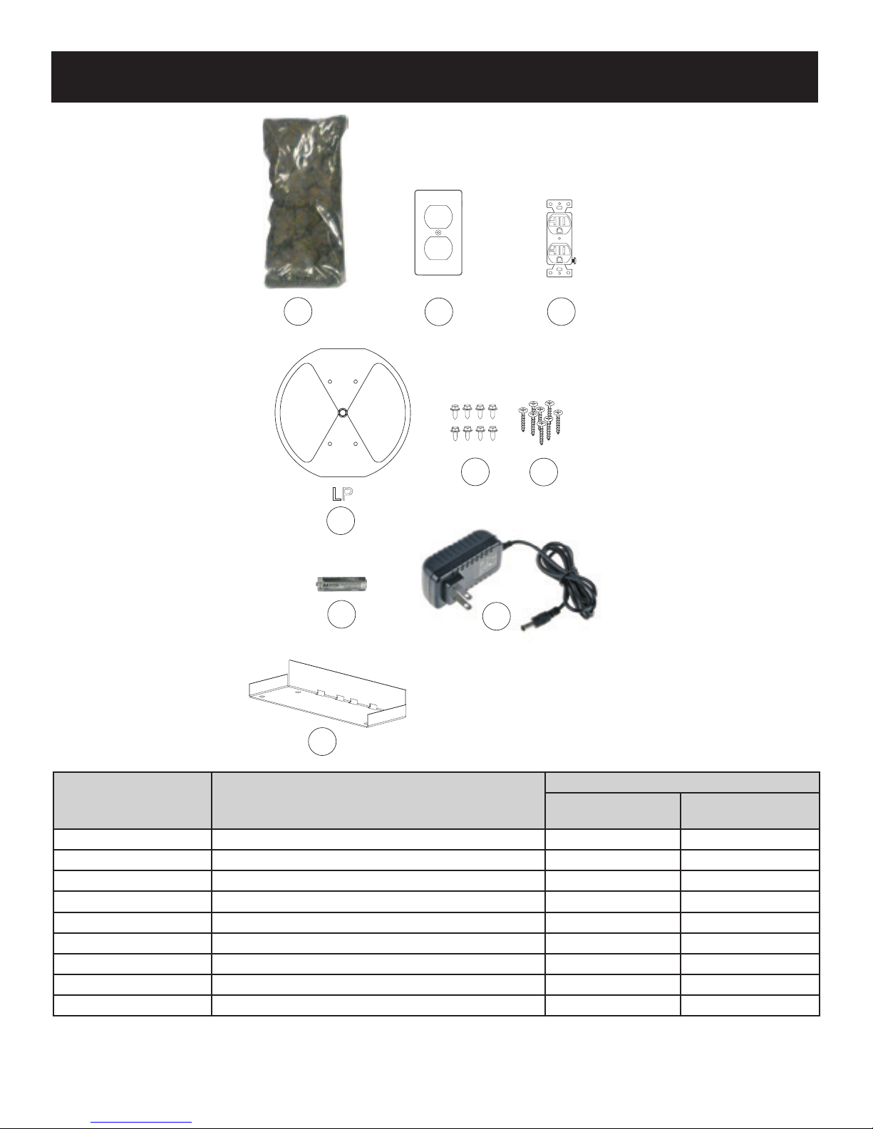
CARTON CONTENTS
1
2
5
3
6
LP
4
7
8
10
9
NOTICE: Items not shown to scale.
INDEX
NUMBER
1 Rock Wool 1 1
2 Receptacle Cover 1 2
3 Receptacle 1 2
4 Flue Restrictor Assembly - (See Page 30) 1 1
5 10 X 1/2 Phillips Screw 12 12
6 #8 X 1 Self-Drilling Drywall Screw 8 8
7 AA Battery 0 4
8 AC Adaptor 0 1
9 Backer Stud 4 4
See Parts Lists on pages 48 - 51 for ordering replacement parts. Do not order batteries, bolts, screws, washers or nuts. They are
standard hardware items and can be purchased at any local hardware store.
DESCRIPTION
QUANTITY SUPPLIED
DVCP(32,36,42)BP3
SERIES
DVCP(32,36,42)BP7
SERIES
37607-1-0817Page 6
INTRODUCTION
The information in this manual pertains to all models and gas
control systems unless otherwise noted.
Instructions to Installer
1. Leave this manual with homeowner.
2. Have the homeowner complete the product registration card
or register online at www.empirecomfort.com
3. Show the homeowner how to start and operate the replace.
Notes to Installer
• This direct-vent replace is designed to:
- Operate with combustion air drawn from outside of the
building.
- Expel all exhaust gases to the outside of the building.
• The installation must conform with local codes or, in the
absence of local codes, with the National Fuel Gas Code
ANSI Z223.1/NFPA 54* Natural Gas and Propane Installation
Code, or CSA B149.1 in Canada. * Available from the
American National Standards Institute, Inc. 11 West 42nd
St., New York, N.Y. 10036
• Any alteration of the original design, installation other than
as shown in these instructions, or use with a type of gas not
shown on the rating plate is the responsibility of the person
and company making the change.
• This replace is not for use with solid fuels.
• These replace models may be installed in a bedroom or
bed-sitting room in the U.S.A. and Canada.
WARNING
Any change to this replace can be dangerous. Improper
installation or use can cause serious injury or death from
re,burns,explosionorcarbonmonoxidepoisoning.
FireplaceCertication
This replace is design certied in accordance with American
National Standard/CSA Standard ANSI Z21.88/CSA 2.33 and by
Underwriters Laboratories as a Direct Vent Gas Fireplace Heater
and shall be installed according to these instructions.
Consult your local building code agency, prior to installation,
to ensure compliance with local codes-including permits and
inspections.
The replace, when installed, must be electrically grounded in
accordance with local codes or, in absence of local codes, with
the National Electric Code ANSI/NFPA 70 or Canadian Electric
code, CSA C22.1, if an external electrical source is utilized.
QualiedInstallingAgency
Installation and replacement of gas piping, gas utilization
equipment or accessories and repair and servicing of equipment
shall be performed only by a qualied agency. The term “qualied
agency” means any individual, rm, corporation or company
which either in person or through a representative is engaged
in and is responsible for (a) the installation or replacement of
gas piping or (b) the connection, installation, repair or servicing
of equipment, who is experienced in such work, familiar with all
precautions required and has complied with all the requirements
of the authority having jurisdiction.
Commonwealth of Massachusetts: The installation must be
made by a licensed plumber or gas tter in the Commonwealth
of Massachusetts. Requirements on Page 53.
High Altitude (USA)
When installing this replace at an elevation above 2000 feet
(in the United States) it may be necessary to decrease the input
rating by changing the existing burner orice to a smaller size.
Generally, input should be reduced 4 percent for each 1000 feet
above sea level.
37607-1-0817 Page 7
High Altitude (CANADA)
Altitude: 0-4500 feet (0-1370 meters)
When installing this replace at an elevation above 4500 feet
(in Canada), check with local authorities.
Consult your local gas utility for assistance in determining the
proper orice for your location.
SPECIFICATIONS
DVCP32NAT DVCP32LP DVCP36NAT DVCP36LP DVCP42NAT DVCP42LP
Input BTU/Hr Maximum 24,000 22,000 24,000 24,000 28,500 26,500
Input BTU/Hr Minimum (millivolt only) 18,000 18,000 18,000 19,000 21,000 22,000
KWH (Maximum) 7.03 6.45 7.03 7.03 8.35 7.77
KWH (Minimum) 5.27 5.27 5.27 5.57 6.15 6.3
Orice 42 54 42 1.45mm 39 1.55mm
Air Shutter Opening 3/16-in Full Open 3/16-in Full Open 1/8-in Full Open
Gas Inlet Shutoff Valve (Pipe) 1/2 NPT 1/2 NPT 1/2 NPT 1/2 NPT 1/2 NPT 1/2 NPT
NOTICE:
optimum performance.
Air shutters are factory set for typical venting. Some venting congurations may require minor air shutter adjustments for
GAS SUPPLY PRESSURES
GAS TYPE MAXIMUM MINIMUM MANIFOLD
NAT 14.0-in 4.5-in 3.5-in
LP 14.0-in 10.8-in 10.0-in
Remote Control Options
And Accessories
FRBC Millivolt Battery Remote ON/OFF ALL
FRBTC Millivolt Battery Remote Thermostat ALL
TMW Millivolt Wireless Wall Thermostat ALL
TRW Millivolt Reed Switch Wall Thermostat ALL
FWS-1 Direct Ignition/Millivolt Wall Switch ALL
FRBTP Battery Operated Remote Control with Programmable Thermostat ALL
RVKN-1 Remote Kit, NAT (Stepper Motor) DVCP(32,36,42)BP7N
RVKP-1 Remote Kit, LP (Stepper Motor) DVCP(32,36,42)BP7P
Venting Options Description
DVVK-4TSP Top vent kit (horizontal) - 4-½-in to 6-in (114.3mm to 152mm) wall thickness
DVVK-4TP Top vent kit (horizontal) - 8-in to 12-in (203mm to 305mm) wall thickness
DVVK-4VP Vertical vent kit
DVVK-4F Horizontal ex vent kit (4ft FLEX)
SD46DVA-FCFX7 Flex Adaptor Collar (must be used with ex kits)
Description Models Used On
Conversion Kits Description Used On
31768 Conversion Kit, DV (Natural to Propane) DVCP32BP30
31769 Conversion Kit, DV (Propane to Natural) DVCP32BP30
31770 Conversion Kit, DV (Natural to Propane) DVCP36BP30
31771 Conversion Kit, DV (Propane to Natural) DVCP36BP30
31772 Conversion Kit, DV (Natural to Propane) DVCP42BP30
31773 Conversion Kit, DV (Propane to Natural) DVCP42BP30
32874 Conversion Kit, DV (Natural to Propane) DVCP32BP70
32875 Conversion Kit, DV (Propane to Natural) DVCP32BP70
32876 Conversion Kit, DV (Natural to Propane) DVCP36BP70
32877 Conversion Kit, DV (Propane to Natural) DVCP36BP70
32878 Conversion Kit, DV (Natural to Propane) DVCP42BP70
32879 Conversion Kit, DV (Propane to Natural) DVCP42BP70
37607-1-0817Page 8
ACCESSORIES
The following accessories are available from your Empire Comfort Systems dealer. If you need additional information beyond what your
dealer can furnish, contact Empire Comfort Systems Inc., 918 Freeburg Ave., Belleville, Illinois 62220-2623 or info@empirecomfort.com.
OPTIONAL
DVCP32 DVCP36 DVCP42 Description
DVP32FAB DVP36FAB DVP42FAB Liner, Aged Brick, Ceramic Fiber
DVP32FCB DVP36FCB DVP42FCB Liner, Cottage Brick, Ceramic Fiber
DVP32FRB DVP36FRB DVP42FRB Liner, Rustic Brick, Ceramic Fiber
DVP32LKR DVP36LKR DVP42LKR Liner, Black Reective
FBB10 FBB10 FBB10 Blower, Auto Variable-Speed
LK6 LK6 LK6 Lighting Kit, 120 V
REQUIRED
This unit requires Ceramic Fiber Logs to complete the replace interior. Contact your Empire Comfort Systems Dealer (See Page 55)
for further information. Do not operate the replace without the Ceramic Fiber Logs installed.
37607-1-0817 Page 9
FIREPLACE DIMENSIONS
VENT COLLAR
NAILING
FLANGES
BARRIER SCREEN ASSEMBLY
&
GLASS FRAME ASSEMBLY
GAS LINE
ACCESS
RATING PLATEAND
LABELS INSIDE
GAS CONTROL AND
SWITCHES INSIDE
A
K
L
LEFT VIEW
FRONT VIEW
TOPVIEW
RIGHT VIEW
P
M
GAS LINE
ACCESS
N
O
SIDE STANDOFF
TOPSTANDOFF
G
I
J
C
GAS LINE
ACCESS
INDEX
LETTER
DIMENSION DESCRIPTION
A The maximum height of replace face (excluding standoffs) 38-1/4 38-1/4 40-1/4
B The maximum width of the replace face (excluding nailing anges) 34-7/16 37-7/16 43-7/16
C The maximum depth of the replace 17-1/2 17-1/2 17-1/2
D The height of the replace opening 31-3/8 31-3/8 33-3/8
E The width of the replace opening 31 34 40
F The interior depth of the replace (not shown) 11-1/2 11-1/2 11-1/2
G The rear exterior width of the replace 23-15/16 26-15/16 32-15/16
I Width from the left side of the replace to the centerline of vent 12 13-1/2 16-1/2
J Depth from back of replace to centerline of top vent 6-3/4 6-3/4 6-3/4
K Height from the bottom of the replace to the left gas line opening 2 2 2
L Depth from the front of the replace to the left gas line opening 4-5/8 4-5/8 4-5/8
M Depth from rear of replace to gas line opening 12-5/16 12-5/16 12-5/16
N Viewing area height 24-7/8 24-7/8 26-3/8
O Viewing area width 27-1/2 30-1/2 36-1/2
P Depth from front of replace to centerline of vent 10-3/4 10-3/4 10-3/4
Q Distance from oor to bottom replace opening 7/8 7/8 7/8
R Distance from oor to top replace opening 32-1/4 32-1/4 34-1/4
R
D
E
B
Q
DVCP32 DVCP36 DVCP42
(Inches)
37607-1-0817Page 10
FBB10 BLOWER KIT INSTALLATION (OPTIONAL)
Back side of Blower
showing Velcro
BEFORE FIREPLACE IS INSTALLED IN WALL
1. With power turned off, remove plate and four screws from left
panel. See Figure 1.
Figure 1
2. Install the blower onto the pre-bent brackets on the blower
plate. Ensure the Velcro connects to secure the blower in
place. See Figure 2.
AFTER FIREPLACE IS INSTALLED IN WALL
NOTICE: Do not handle barrier screen or door with your bare
hands! (Always Wear Gloves)
1. Turn off power and gas. Lift barrier screen and pull away
from the unit. See Figure 4.
Figure 4
2. Pull outward to release both latches at bottom of rebox
assembly. See Figure 5.
Figure 2
3. Route wiring through opening created in Step 1.
4. Secure blower assembly into place per step 2 with velcro.
5. Install thermo disc by snapping into valve bracket burner
assembly. See Figure 3.
Figure 3
6. Connect power source into outlet on the bottom right side of
the replace.
Figure 5
3. Disengage Glass Frame by pulling outward in a swinging
motion. Place Glass Frame aside in a safe out-of-the-way
location. See Figure 6.
Figure 6
37607-1-0817 Page 11
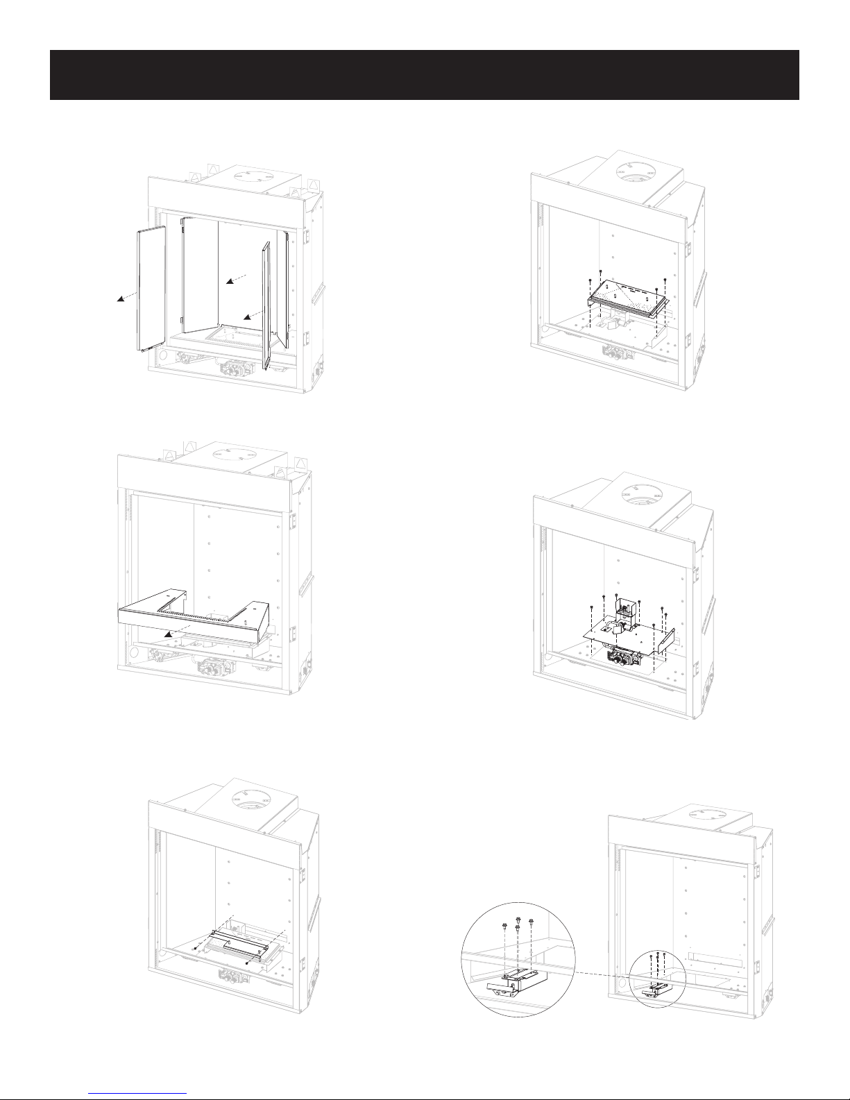
FBB10 BLOWER KIT INSTALLATION (OPTIONAL) (CONT’D)
4. Remove log set and decorative media. Remove brackets
and liners if installed. Retain bracket and screws for
reassembly. SeeFigure7.(Reectivelinersshown)
Figure 7
5. Remove burner cover by lifting off. See Figure 8.
7. Remove the four screws securing burner and slide to right
then lift burner off. Retain burner and screws for reassembly.
See Figure 10.
Figure 10
8. Remove ten screws and lift burner assembly. Disconnect
gas line. Retain screws and burner assembly for reassembly.
See Figure 11.
Figure 8
6. Remove log support by removing the two screws securing
the metal plate to log support. Retain log support and screws
for reassembly. See Figure 9.
Figure 9
Figure 11
9. Remove the four screws securing the left latch assembly
to the underside of the rebox. Retain screws and latch
assembly for reassembly. See Figure 12.
Figure 12
37607-1-0817Page 12
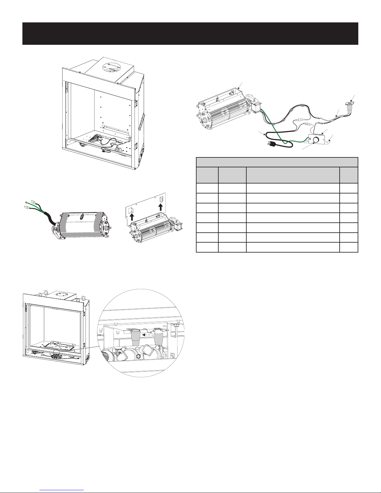
Back side of Blower
showing Velcro
FBB10 BLOWER KIT INSTALLATION (OPTIONAL) (CONT’D)
2
10. Install blower through rebox cutout. See Figure 13.
Figure 13
11. Install the blower onto the pre-bent brackets on the blower
plate. Ensure the Velcro connects to secure the blower in
place. See Figure 14.
21. Turn on power.
22. Reinstall the glass frame removed in steps 2 and 3. See
Figures 5 and 6.
23. Replace barrier screen removed in step 1. See Figure 4.
1
7
3
4
5
6
BLOWER ASSEMBLY PARTS LIST
INDEX
NO.
PART
NO
DESCRIPTION QTY
1 R2804 Blower Assembly 1
2 R7649 Fan, Control L120-20 1
3 R2099 Cord Set, 30-Inches 1
4 R4192 Rheostat, Knob 1
5 R4186 Rheostat, 3.0 AMP 115 VAC 1
6 10088 Rheostat Box Bracket 1
7 R11768 Wire Harness, Fan Control 1
Figure 14
12. Reinstall the latch assembly removed in step 9. See Figure 12.
13. Install thermo disc by snapping into valve bracket burner
assembly. See Figure 15.
Figure 15
14. Reconnect gas line and turn gas on. Check for leaks.
15. Reinstall the burner assembly and ten screws removed in
step 8. See Figure 11.
16. Reinstall the burner and four screws removed in step 7.
See Figure 10.
17. Reinstall the log support and secure it with metal plate and
two screws removed in step 6. See Figure 9.
18. Replace burner cover removed in step 5. See Figure 8.
19.
Replace liner and bracket if removed in step 4. See Figure 7.
20. Replace log set and decorative media.
Figure 16
37607-1-0817 Page 13
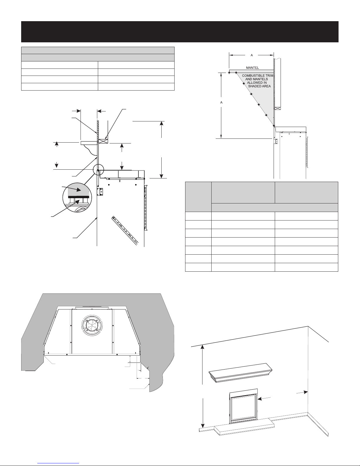
CLEARANCES
SEE MANTLE CHART FOR
MAXIMUM MANTEL DEPTH
GLASS FRONT
FINISHED WALL
(NON-COMBUSTIBLE)
SEE MANTEL CHART
FOR MINIMUM HEIGHT
OF MANTLE ABOVE UNIT
2"x4" HEADER
MINIMUM TO
CHASE TOP
24”
FINISHED WALL
(COMBUSTIBLE)
9”
(NON-COMBUSTIBLE)
BOARD
SCREW HEAD
FIREPLACE
(TOP VIEW)
PERPENDICULAR
SIDE WALL
45°
6
3
MAX.
FRONT FACE (SIDE)
COMBUSTIBLE
MATERIALS ALLOWED
IN SHADED
AREAS
G
F
E
D
C
B
CLEARANCE TO COMBUSTIBLES
(Inches)
Back 0
Side 0
Floor 0
Top Framing Edge See Below
Figure 17
Combustible Material
No greeting cards, stockings or ornamentation of any type should
be placed on or attached to the replace. The ow of heat can
ignite combustibles.
Mantel Chart
FIREPLACE OPENING
INDEX
LETTER
DISTANCE FROM TOP
EDGE OF FIREPLACE
(VERTICAL)
DISTANCE FROM
FIREPLACE FRONT
(HORIZONTAL)
(Inches)
A 18 12
B 6 0
C 9 2-1/4
D 11 3-3/4
E 14 6
F 16-3/4 8
G 18 10
Figure 19
Clearances
Clearance from bottom edge of replace to ceiling is 72-inches.
Clearance from side of replace to adjacent sidewall is 6-inches.
Refer to framing dimensions on page 22.
NOTICE: 72 inch minimum applies when unit is installed in wall
above oor level.
Figure 18
72”
(183cm)
6” (152mm)
Figure 20
37607-1-0817Page 14
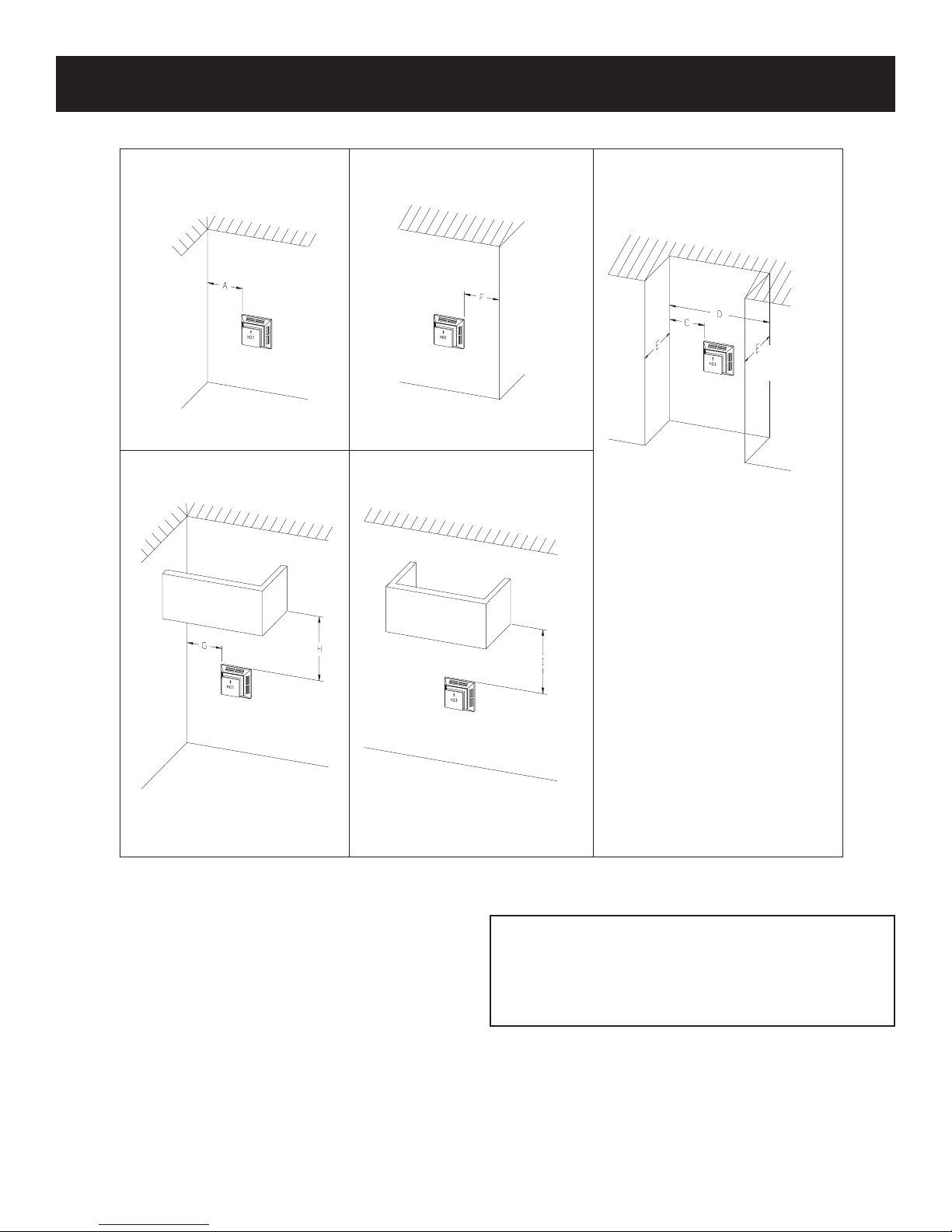
TERMINATION CLEARANCES
RECESSED LOCATION
OUTSIDE CORNER
INSIDE CORNER
“A”=COMBUSTIBLE 9-in (229mm)
= NONCOMBUSTIBLE2-in (51mm)
“F”=COMBUSTIBLE 6-in (152mm)
= NONCOMBUSTIBLE 6-in (152mm)
BALCONY
WITH PERPENDICULAR SIDE WALL
BALCONY
WITH NO SIDEWALL
“C”=CLEARANCE FROM CORNER
IN RECESSED LOCATION
COMBUSTIBLE 9-in (229mm)
NONCOMBUSTIBLE 2-in (51mm)
“D”=MINIMUMWIDTHFOR BACK WALL
OF A RECESSED LOCATION
COMBUSTIBLE 38-in (965mm)
NONCOMBUSTIBLE 24-in (610mm)
“E”=MAXIMUM DEPTHOF48-in (1219mm)
FOR RECESSED LOCATION
“G”=COMBUSTIBLE 9-in (229mm)
= NONCOMBUSTIBLE 2-in (51mm)
“H”=COMBUSTIBLE18-in (457mm)
= NONCOMBUSTIBLE 12-in (305mm)
“I” = COMBUSTIBLE 12-in (457mm)
= NONCOMBUSTIBLE 12-in (305mm)
Termination clearance for buildings with combustible and noncombustible exteriors.
Vertical Sidewall Installations
Important! Minimum clearance between vent pipes and
combustible
materials is 3 inches (76 millimeter) on top, and 2
inches (25 millimeter) on bottom and sides.
Important! When vent termination exits through foundation less
than 20 inches (508 millimeter) below siding outcrop, the vent
pipe must extend outward so that the horizontal vent termination
is located ush to, or beyond the outcrop siding.
Information on Various Venting Routes and Components
Important: Locate the replace in such a way that minimizes the
number of offsets and horizontal vent length.
Venting system must maintain a balance between the
combustion air intake and the ue gas exhaust. Limitations to
vent congurations apply.
37607-1-0817 Page 15
Figure 21
ATTENTION: Vinyl Soft, Vinyl Ceiling, Vinyl Overhang
Disclaimer
Clearances are to heat resistant material (i.e. wood, metal). This
does not include vinyl. Empire Comfort Systems Inc. will not be held
responsible for heat damage caused from terminating under vinyl
overhangs, vinyl ceilings or vinyl ventilated/unventilated softs.

VENT TERMINAL CLEARANCES
Canadian Installations1 US Installations2 Canadian Installations1 US Installations2
A= Clearance above
grade, veranda, porch,
deck, or balcony
B= Clearance to window or
door that may be open
C= Clearance to
permanently
closed window
D= Vertical clearance
ventilated soft located
above the terminal within
a horizontal distance of
2 feet (61 cm) from the
center line of the terminal
E= Clearance to
unventilated
soft
F= Clearance to
outside corner
G= Clearance
inside corner
H= Clearance to each side
of center line extended
above meter/regulator
assembly
ATTENTION:VinylSoft,VinylCeiling, VinylOverhang
Disclaimer
Clearances are to heat resistant material (i.e. wood, metal). This
does not include vinyl. Empire Comfort Systems Inc. will not be
held responsible for heat damage caused from terminating under
vinyl overhangs, vinyl ceilings or vinyl ventilated/unventilated softs.
12-in (30cm) 12-in (30cm) I= Clearance to service
6-in (15cm) for appliances ≤ 10,000 Btuh
(3kW), 12-in (30cm) for
appliances > 10,000
Btuh (3kW) and ≤
100,000 Btuh (30kW),
36-in (91cm) for appliances > 100,000 Btuh
(30kW)
12-in (30cm) 12-in (30cm)
24-in (61cm) 24-in (61cm)
12-in (30cm) 12-in (30cm)
6-in (15cm) 6-in (15cm)
9-in (23cm) 9-in (23cm)
3ft (91cm) within a
height 15ft (4.5m)
above the meter/regulator assembly
6-in (15cm) for appliances ≤ 10,000 Btuh
(3kW), 9-in (23cm) for
appliances > 10,000
Btuh (3kW) and ≤
50,000 Btuh (15kW),
12-in (30cm) for appliances > 50,000 Btuh
(15kW)
3ft (91cm)
regulator vent outlet 3ft (91cm) 6ft
J= Clearance to nonme-
chanical air supply
inlet to building or the
combustion air inlet to
any other appliance
K= Clearance to a
mechanical air
supply inlet
L= Clearance above
paved sidewalk or
paved driveway
located on public
property
M= Clearance under
veranda, porch
deck, or balcony
1 In accordance with the current CSA B149.1, Natural Gas and Propane
Installation Code
2 In Accordance with the current ANSI Z223.1/NFPA 54, National Fuel Gas
Code
† A vent shall not terminate directly above a sidewalk or paved driveway that
is located between two single family dwellings and serves both dwellings
‡ Permitted only if veranda,, porch, deck, or balcony is fully open on a mini-
mum of two sides beneath the oor.
* For clearances not specied in ANSI Z223.1/NFPA 54 or CSA B149.1, one
of the following shall be indicated:
Clearance in accordance with local installation codes and the requirements of the
gas supplier.
6-in (15cm) for appliances ≤ 10,000 Btuh
(3kW), 12-in (30cm) for
appliances > 10,000
Btuh (3kW) and ≤
100,000 Btuh (30kW),
36-in (91cm) for appliances > 100,000 Btuh
(30kW)
6ft (1.83m)
7ft (2.13m) † 7ft (2.13m) †
12-in (30cm) ‡ 12-in (30cm) ‡
6-in (15cm) for appliances ≤ 10,000 Btuh
(3kW), 9-in (23cm) for
appliances > 10,000
Btuh (3kW) and ≤
50,000 Btuh (15kW),
12-in (30 cm) for appliances > 50,000 Btuh
(15kW)
3ft (91cm) above if
within 10ft (3m)
horizontally
Figure 22
37607-1-0817Page 16
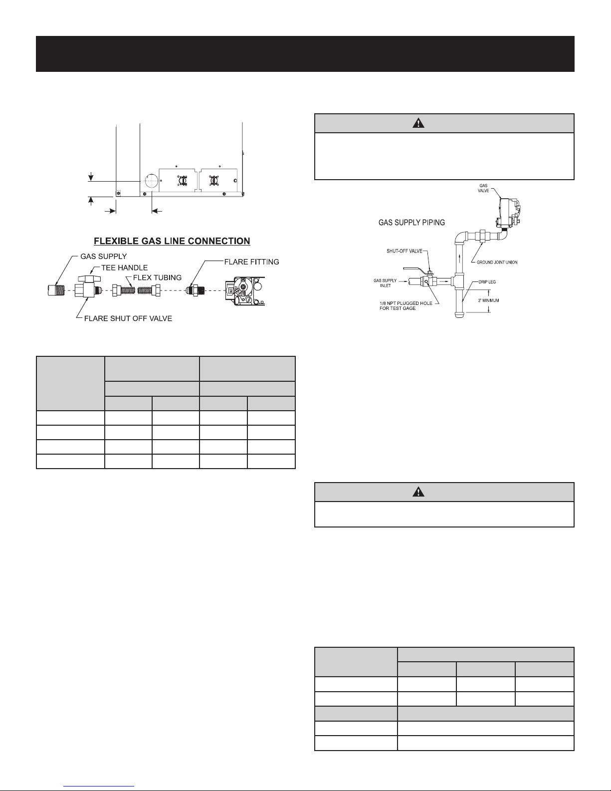
GAS SUPPLY
The gas pipeline can be brought in through the right or left side of
the appliance. Consult the current National Fuel Gas Code, ANSI
Z223.1 CAN/CGA-B149 (.1 or .2) installation code.
RIGHT SIDE OF FIREBOX
2”
4 5/8”
Figure 23
Figure 24
Recommended Gas Pipe Diameter
Schedule 40 Pipe
Pipe Length
0-10 feet 1/2 3/8 1/2 3/8
10-40 feet 1/2 1/2 5/8 1/2
40-100 feet 1/2 1/2 3/4 1/2
100-150 feet 3/4 1/2 7/8 3/4
NOTICE: Never use plastic pipe. Check to conrm whether your
local codes allow copper tubing or galvanized.
NOTICE: Because some municipalities have additional local codes,
consult your local authority and installation code.
The use of the following gas connectors is recommended:
— ANSI Z21.24 Appliance Connectors of Corrugated Metal Tubing
and Fittings.
— ANSI Z21.45 Assembled Flexible Appliance Connectors of
Other Than All-Metal Construction
The above connectors may be used if acceptable by the authority
having jurisdiction. The Commonwealth of Massachusetts requires
that a exible appliance connector cannot exceed three feet in length.
A gas valve and ground joint union should be installed in the gas
line upstream of the gas control to aid in servicing. It is required
by the National Fuel Gas Code that a drip leg be installed near the
gas inlet. See Figure 25. This should consist of a vertical length of
pipe tee connected into the gas line that is capped on the bottom
in which condensation and foreign particles may collect.
Installing a New Main Gas Supply Valve (Check Local Code)
Each appliance should have its own manual gas supply valve.
A manual main gas supply valve should be located in the vicinity of the
unit. Where none exists, or where its size or location is not adequate,
contact your local authorized installer for installation or relocation.
Compounds used on threaded joints of gas piping shall be resistant
to the action of liqueed petroleum gases.
Inside Diameter
(Inches) (Inches)
Nat LP Nat LP
Tubing, Type L
Outside Diameter
The gas lines must be checked for leaks by the installer. This should
be done with a soap solution watching for bubbles on all exposed
connections, and if unexposed, a pressure test should be made.
WARNING
Neveruseanexposedametocheckforleaks.Appliance
must be disconnected from piping at inlet of control valve and
pipe capped or plugged for pressure test. Never pressure test
withapplianceconnected;controlvalvewillsustaindamage!
Figure 25
NOTICE: The millivolt gas controls are equipped with a captured
screw type pressure test point, therefore it is not necessary to provide
a 1/8 inch test point up stream of the control.
On direct ignition valves, hex plugs may be replaced with hose ttings
for pressure checks, then reinstalled before operating replace.
When using copper or ex connector use only approved ttings.
The replace and its individual shut off valve must be disconnected
from supply piping system during any pressure testing of that system
at test pressures in excess of 1/2 psig (3.5kPa).
The replace must be isolated from the gas supply piping system
by closing its individual manual shut off valve during any pressure
testing of the gas supply piping system at test pressures equal to
or less than 1/2 psig (3.5kPa).
WARNING
Pressures in excess of 1/2 psig (14 inches w.c.) (3.5kPa) on
thereplacegasvalve,maydamagethevalve.
Checking Manifold Pressures
Both Propane and Natural gas valves have a built-in pressure regulator.
Natural gas models will have a manifold pressure of approximately 3.5
inches w.c. (.871kPa) at the valve outlet with the inlet pressure to the
valve from a minimum of 4.5 inches w.c. (1.120kPa) for the purpose
of input adjustment to a maximum of 14.0 inches w.c. (3.484kPa).
Propane gas models will have a manifold pressure approximately 10.0
inches w.c. (2.49kPa) at the valve outlet with the inlet pressure to the
valve from a minimum of 10.8 inches w.c. (2.68kPa) for the purpose
of input adjustment to a maximum of 14.0 inches w.c. (3.484 kPa).
Gas Supply Pressure (inches w.c.)
Minimum Normal
Natural Gas 4.5 7.0
LP (Propane) 10.8 11.0
Manifold Pressure (inches w.c.)
Natural Gas 3.5 - Normal (HI)
LP (Propane) 10.0 - Normal (HI)
Maximum
14.0
14.0
37607-1-0817 Page 17
 Loading...