

EmpirBus NXT DCM User Manual

!
EmpirBus!NXT!DCM!
User!manual!
!

1/15 EmpirBus NXT DCM User manual Ver 1.53
1. Introduction .................................................................................................................................... 2
2. Safety guidelines and measures ...................................................................................................... 2
3. Scope of Delivery ............................................................................................................................. 2
4. Model Range ................................................................................................................................... 2
5. Installation ...................................................................................................................................... 2
5.1 Mounting ....................................................................................................................................... 2
5.2 Connectors .................................................................................................................................... 3
5.3 Power feed .................................................................................................................................... 3
6. Circuits ............................................................................................................................................ 4
6.1 Inputs ............................................................................................................................................ 4
6.1.1 Digital input – negative .......................................................................................................... 4
6.1.2 Digital input – positive ........................................................................................................... 5
6.1.3 Digital input – commonline .................................................................................................... 5
6.1.4 Analog input – resistance ....................................................................................................... 5
6.1.5 Analog input – voltage ........................................................................................................... 6
6.1.6 Analog input – multi switch .................................................................................................... 6
6.2 Outputs ......................................................................................................................................... 6
6.2.1 Digital output – positive ......................................................................................................... 6
6.2.2 Digital output – half bridge .................................................................................................... 7
6.2.3 Digital output – Window wiper .............................................................................................. 7
7. Configuration .................................................................................................................................. 8
7.1 Bus ID ............................................................................................................................................ 8
7.2 Fuse reset ...................................................................................................................................... 8
7.3 Manual channel override .............................................................................................................. 8
7.3.1 Manual override switch off .................................................................................................... 8
7.3.2 Manual override switch on .................................................................................................... 9
7.3.3 Resetting a channel ................................................................................................................ 9
7.4 Wireless transmitter pairing ......................................................................................................... 9
8. Product specifications ................................................................................................................... 10
!
EmpirBus NXT DCM User manual Ver 1.53 2/15
1. Introduction!
The DCM is a product from the EmpirBus NXT product family.
This document contains basic specifications, installation instructions, manual channel override and
fuse reset instructions. This and other documents are available at www.empirbus.com.
2. Safety!guidelines!and!measures!
In order to avoid accidental short circuits, make sure to disconnect the power supply to the DCM
before making any connections.
Never use this product where there is a danger of dust or gas explosion or other potentially
flammable products.
3. Scope!of!Delivery!
If the DCM is equipped with an integrated wireless receiver, a stub antenna is included in the box.
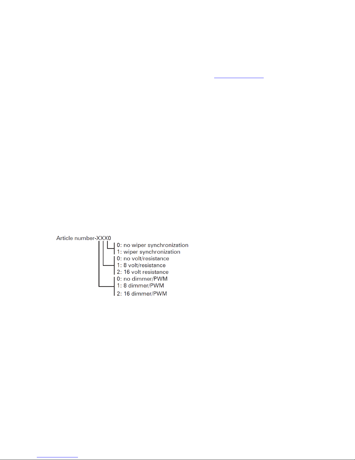
4. Model!Range!and!options!
Both the unit and the box are marked with model number and option specification. Each unit has a
total of 16 configurable channels. For channel specification, see table 9.1: Model range
The options are specified by the last four digits in the article number.
E.g. A 2010103-1100 can control up to 8 analog inputs and 8 PWM outputs.
5. Installation!
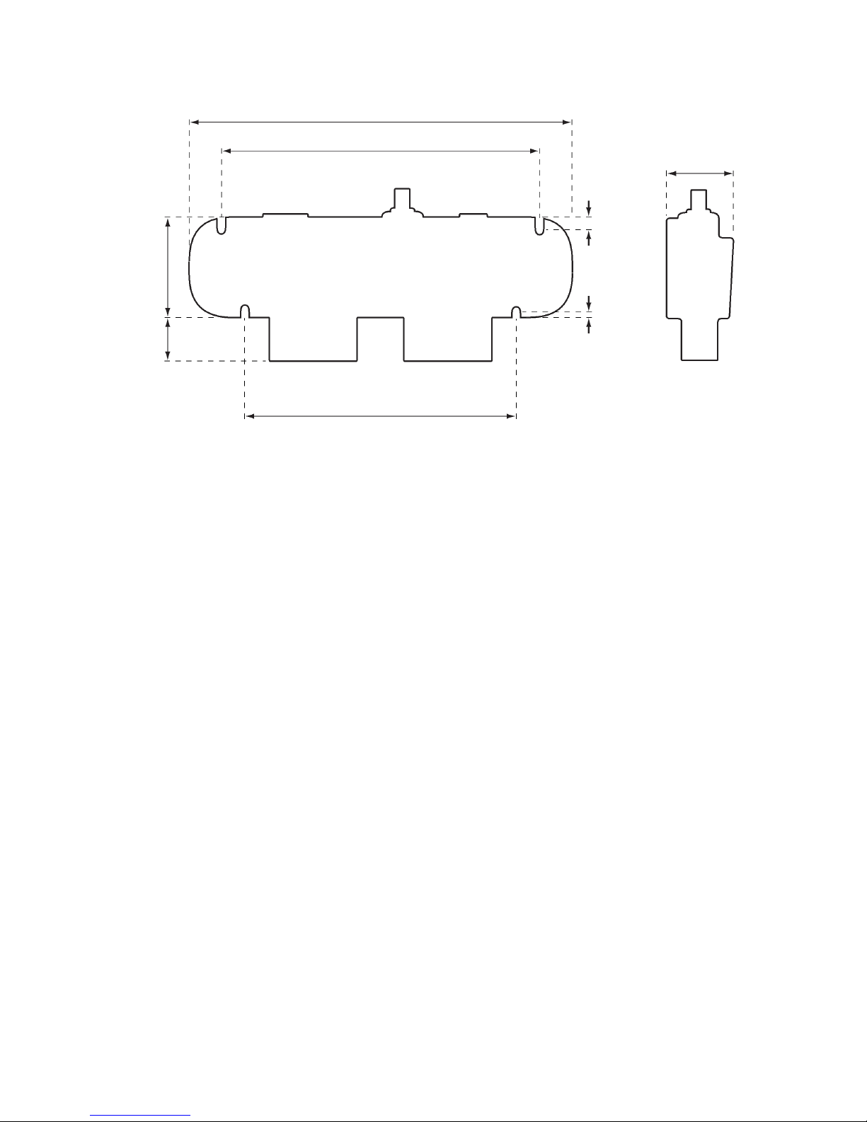
5.1!Mounting!
The DCM should be mounted on a flat vertical surface with four screws (not included), with the
orientation as shown in figure 5.1.
Figure 4.1: Options
3/15 EmpirBus NXT DCM User manual Ver 1.53
5.2!Connectors!
The bus connector is an NMEA2000 compatible male Micro-C 5 pin connector. It is not recommended
to connect a T-connector directly to the unit; a drop cable should be between the main bus and the
unit.
The consumers and inputs are connected via Molex MX150L connectors. Only use correct crimp and
extractor tools when assembling the connector. Unused pins in the connector should be plugged
with circuit plugs in order to maintain IP65.
5.3!Power!feed!
The power is supplied on the two M6 bolts with positive on the left (marked with +) and negative on
the right (marked with -). The total max output of a DCM is 100A.
!
59
27
229
190
8,5
4,5
162
41
[mm] (Drawing is not to scale.)
Figure 5.1: Dimensions
EmpirBus NXT DCM User manual Ver 1.53 4/15
6. Circuits!
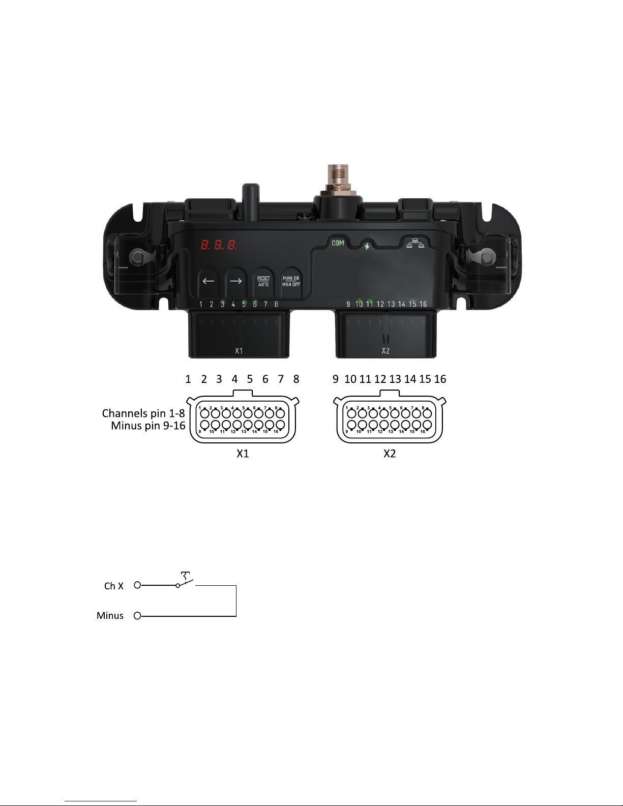
The usage of a channel is determined by the model, option configuration and programming. The
channels are numbered directly on the unit (1 through 16). The channels (inputs/outputs) are on the
upper row of pins and the lower row is minus. See figure 6.1. The Molex MX150L connectors
connector accepts cable dimensions up to 2,5 mm2.
6.1!Inputs!
Any channel on a DCM can be configured as digital or analog input. If options support analog inputs
or
6.1.1!Digital!input!–!negative!
Connect the switch directly between minus and the desired channel.
!
Figure 6.1: DCM pinout
 Loading...