

Page 1

CL85 CL65 CL60
Installer's Guide
In-Ceiling LCR Speakers
from EMPHASYS have been created to
meet the needs of today’s discriminat-
ing listener, offering a blend of clarity
and output that’s equal to the needs
of a high-performance home theater
or distributed audio system. In fact,
an EMPHASYS In-Ceiling LCR can
be just as appropriate as the center
channel speaker as it is in a left/right
pairing. The In-Ceiling LCR Series re-
ally delivers, with superb components
and great sound in a range of sizes.
This manual is designed to facilitate
easy installation and adjustment of
the EMPHASYS In-Ceiling LCR speak-
ers. To ensure the best performance,
Positioning the Speakers
EMPHASYS In-Ceiling LCR speak-
ers, with their superior clarity and
power handling, provide excep-
tional versatility for the home
theater environment. A single
LCR speaker can be used for the
front center channel, or a pair
can be used for left and right in
the front or rear of the system.
The In-Ceiling LCR Speaker as a Center Channel
In-Ceiling LCR speakers are designed to blend seamlessly with other EMPHASYS speak-
ers and accessories, and will satisfy almost any installation. However, if the LCR is to be
used as a center channel speaker, it should be placed directly above the TV. Additionally,
system performance can be enhanced if the center channel speaker is aligned as closely
please follow the instructions carefully.
as possible with the horizontal plane of the front left and right speakers.
Page 2

Speaker Adjustments
Bass
Treble
0
+3
0
+3
Creating a Zone for Optimized Listening
The In-Ceiling LCR speakers should be placed so that they project, as much as possible, toward the listening position. This will
ensure an accurate stereo image and help minimize the creation
of excessive sound reflections.
If the speakers are to be mounted in a very high ceiling, the pivoting tweeters should be aimed directly toward the listening position. (See Diagram 1)
In other cases it might be preferable to aim the tweeters slightly
outward, away from the listening position.
CAUTION: The tweeter dome, whether aluminum or silk, can be
damaged through direct contact with fingers or objects. Please be
careful when installing and adjusting the speaker.
Preparing the Surface for Mounting
New Construction: Unfinished Ceiling
A new construction bracket, available from your dealer, can be
installed prior to drywall application across joists (up to 24" oncenter) where a speaker will be located. After the hole is cut and
the drywall is installed, the speakers are then easily installed following the instructions for mounting in “Finished Ceiling” below.
Note: If the speakers are to be mounted more than 24" on-center, a
special “extra-long wing” is available from your dealer.
Diagram 1:
Tweeter
Push Tweeter Here
Cut at a 45° angle toward the inside of the hole. (see Diagram 2)
You can use the cutout piece to fill the hole if obstructions are
encountered.
Diagram 2:
Ceiling Cutout
Finished Ceiling
Prior to the actual installation of the speakers, it will be necessary
to run speaker wire to the locations in which they’ll be mounted.
See your dealer for more information. Then, with the wire in
place, the speakers can be mounted. To ensure a professionallooking result, follow the simple steps described below:
Choose the general location for the installation of each speak-
1.
er, being certain that these areas present no obstructions such as
electrical conduit, HVAC duct work or other elements.
2. Find the joists nearest the desired location for the speaker.
EMPHASYS recommends the use of a good stud finder for this
procedure. If you are lining up the speakers to some other object
or molding in the room, be sure to allow for the size of the baffle
flange. This flange extends beyond the mounting hole on all four
sides of the ceiling speaker.
3. Mark the hole. A template for setting the hole is provided in
the box (as are two paint mask inserts). Position the template in
the desired position and outline it on the ceiling using a pencil.
4. Cut the hole. CAUTION: This is the most important part of the
installation.
tions in the desired mounting area, use a drywall saw to cut a
small hole at the center of the spot you’ve outlined.
If you aren’t certain whether there are any obstruc-
Once the mounting location is deemed to be free of obstructions, cut the outline at a 90° angle relative to the surface of the
ceiling.
5. If the area in the ceiling isn’t already insulated, add insulation
material sufficient to fill the cavity. If the insulation material used is
faced with foil or paper, position the foil or paper away from the
speaker.
2
Page 3
Installing the Speakers
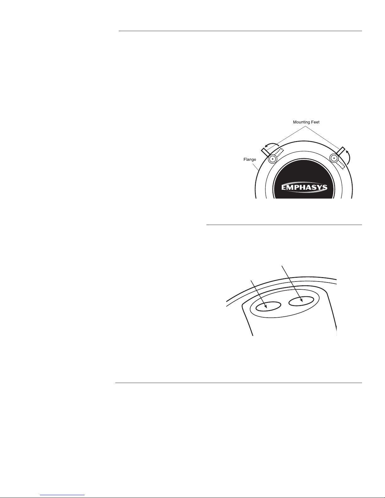
The In-Ceiling LCR speakers feature a mounting system with four
swiveling feet for quick, secure installation. Use the following
steps:
Tighten the four screws on the front of the baffle only so much that
the flange becomes snug against the ceiling. As you tighten the
screws, the feet will flip into an outward position
clamping the drywall between the feet and the flange. CAUTION:
1. Remove the grille. (To force the grille out of its retaining
groove, it may be necessary to push one or two of the mounting screws and its attached foot toward the baffle and against the
Excessive tightening may torque the baffle, crack the ceiling, cause
the white bezel to distort and make it difficult to seat the grille within
the grooves.
inside surface of the grille.)
4. Push the grille firmly into the slot in the speaker baffle.
2. Attach the speaker wire (observing the proper polarity with
your amplifier, matching positive (red) to positive and negative
(black) to negative). Be certain the left channel of the amplifier is
connected to the left speaker, and that the right channel is connected to the right speaker.
3. Be sure the mounting feet are turned inward to clear the
opening, and then insert the speaker into the ceiling. Position the
speaker in the hole. Note: The flange of the speaker is designed
to conform to minor imperfections in the ceiling’s surface.
Adjusting the Frequency Response for CL85
(see Diagram 3),
Diagram 3:
Mounting Feet
Treble Adjustment
The Treble switch allows +3dB of adjustment from the “0” position,
where the most linear frequency response is maintained. If more
treble is desired, simply move the switch to the “+3” position. To
return to the neutral setting, move the switch back to the “0” position. The Treble switch can be adjusted whenever desired.
(See Diagram 4)
Bass Adjustment
The Bass switch provides +3dB of bass adjustment from the “0”
position, where the flattest bass frequency response is maintained.
For extra bass, move the switch to the “+3” position. To return to
the neutral setting, move the switch back to the “0” position. As
with treble adjustment, the Bass switch can be moved whenever
desired. (See Diagram 4)
Painting the Speakers
If the speakers are to be painted, we recommend that it be done
before the speakers are actually installed. However, it is possible
to paint the speakers post-installation. Simply remove them from
the ceiling by reversing the order of the steps for installation
described earlier in this manual.
The paint masks provided in the carton must be installed between
the grille and flange while they are being painted. Be sure to
remove the white plastic blanket from beneath the grille before
painting the speaker. Once the grille has been painted, remove
Diagram 4:
Adjustment Switches
Treble Adjustment Switch
Bass Adjustment Switch
Treble
+3
Bass
+3
0
0
the paint mask and return the acoustic blanket to its position
beneath the grille.
Be careful not to clog the holes of the grille. The sound of the
speakers will be dramatically reduced if the perforations in the
grille are covered in paint.
EMPHASYS recommends only light spray painting using five parts
thinning agent to one part paint.
3
Page 4

Features & Specs
Speaker Type:
Woofer:
Tweeter:
Sensitivity, 2.83V/m:
Power Handling:
Impedance:
Switches:
Frequency Response:
Dimensions:
Cut Out Dimensions:
CL85
Two-way In-Ceiling LCR Speaker
8" Aluminum Woofer
1" Pivoting Aluminum Dome
Tweeter
92dB 1W/1m
175 Watts
8Ω
+3dB Bass & Treble Switches
32Hz - 20kHz
1
Dia 11
⁄2" x Depth 57⁄8"
7
Dia 9
⁄8"
CL65
Two-way In-Ceiling LCR Speaker
1
6
⁄2" Aluminum Woofer
1" Pivoting Aluminum Dome
Tweeter
92dB 1W/1m
125 Watts
8Ω
N/A
36Hz - 20kHz
1
Dia 9
⁄4" x Depth 49⁄16"
1
Dia 8
⁄4"
CL60
Two-way In-Ceiling LCR Speaker
1
6
⁄2" Polypropylene Woofer
1" Pivoting Silk Dome
Tweeter
91dB
100 Watts
8Ω
N/A
40Hz - 20kHz
1
Dia 9
⁄4" x Depth 49⁄16"
1
Dia 8
⁄4"
Limited Ten-Year Warranty
EMPHASYS Audio Systems (“Vendor”) makes no warranties with respect to the
Product or to the use and limitation of authority of the Product, except as set
forth herein or expressly authorized, in writing, by Vendor. Vendor warrants
equipment manufactured by it to be free from defects in material and work-
manship under normal use and regular service and maintenance for the lessor
of 10 years from date of installation or 10 years from the date of purchase. If
within the applicable warranty period purchaser discovers such item was not
as warranted and promptly notifies Vendor in writing Vendor, as its sole liability
and its customers’ exclusive remedy, shall repair or replace the item at Vendor’s
expense or refund the purchase price. Replacement of any item hereunder
shall not operate to extend the original warranty period as to any item, includ-
ing replacement items supplied hereunder. This warranty shall not apply to
equipment (i) not manufactured by Vendor, (ii) which has been repaired or
altered by other than Vendor, or (iii) which shall have been subjected to negli-
gence, misuse, misapplication, accident, fire, abuse, damage by circumstances
beyond Vendor’s control, acts of God, or to improper operation, maintenance
or storage, or to other than normal use or service. The foregoing warran-
ties do not cover reimbursement for labor, transportation, removal, installa-
tion, or other expenses which may be incurred in connection with repair or
replacement. Except as may be expressly provided in an authorized writing
by Vendor, Vendor shall not be subject to any other obligations or liabilities
whatsoever with respect to equipment manufactured by Vendor or services
rendered by Vendor. It is expressly understood that vendor’s standard warranty
is made in lieu of all other warranties, express or implied, including warranties
of merchantability, fitness for a particular purpose and non-infringement, and
all such warranties are hereby disclaimed by vendor and excluded from this
standard warranty. It is further understood that vendor’s liability hereunder
or in connection with the manufacture or sale of the products, whether in
contract, in tort, for infringement, for negligence or otherwise shall be limited
to the terms of this standard warranty. Purchaser agrees that EMPHASYS shall
not, in any event, be liable for special, incidental, indirect or consequential
damages (including, without limitation, any loss of anticipated profits incurred
by buyer). The price stated for the equipment is a consideration in limiting
EMPHASYS' liability.
Technical Support
The Technical Support hotline is ready with answers to questions regarding
this and other products from EMPHASYS. Simply call 866.469.0748. We are
available to assist you every weekday, except holidays, between the hours of
7:00 a.m. and 5:00 p.m. PST.
940 Columbia Avenue, Riverside, CA 92507
866.469.0748 • Fax 951.750.6304 • emphasysav.com
1300-0013000 (rev1)
 Loading...