

Page 1
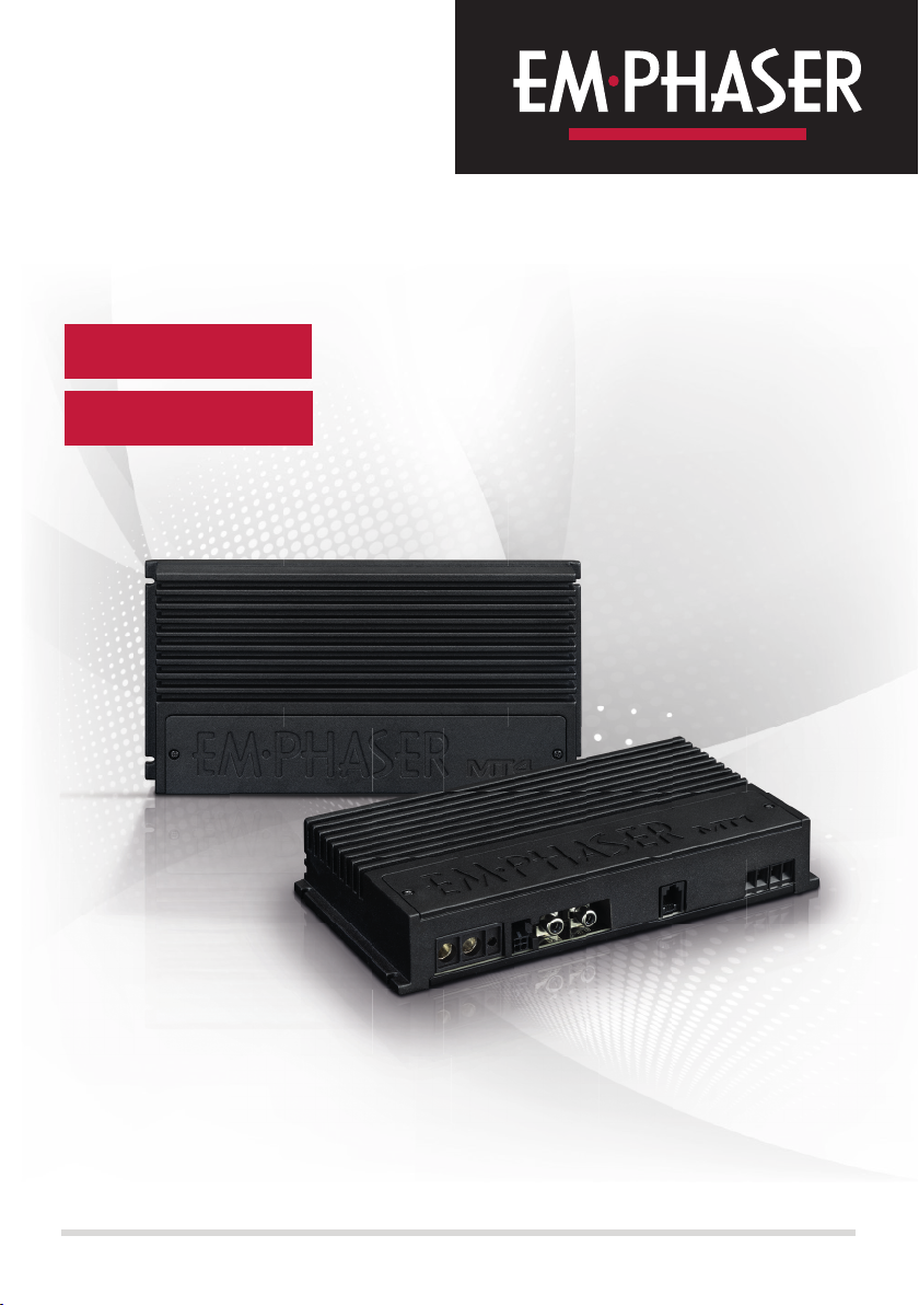
EA-MT1
1-CHANNEL AMPLIFIER
EA-MT4
4-CHANNEL AMPLIFIER
INSTALLATION & OPERATING MANUAL
EINBAU- & BEDIENUNGSANLEITUNG
Page 2
Thank you for purchasing this peerless EMPHASER amplifier!
To maximize the performance of this amplifier and your complete car audio system install, we
recommend that you acquaint yourself thoroughly with all technical features and controlling
options of this EMPHASER amplifier. Please read this manual carefully, before attempting
the installation.
If, after reading this manual, you still have questions regarding functions or the installation of
the amplifier, we recommend that you consult your dealer.
KEY FEATURES
EA-MT1
■ 1-CH Class-D Full-Range Amplifier for 4/2 Ohm Mono Operation
■ Adjustable 12 dB/octave LP an d Subsonic X- Over
■ Remote Control included
■ Bass Boost
■ Protection Circuit
EA- MT4
■ 4-CH Class-D Amp for 4/2 Ohm Stereo Operation
■ Bridge Operation into 4 Ohm
■ Adjustable 12 dB/octave HP and BP X-Over
■ Extended X-Over range for 2-way active speaker setup
■ Protection Circuit
TECHNICAL SPECIFICATIONS
Model EA-MT1 EA- MT4
Number of Channels 1 4
Rated Power Output (RMS)
At 4 Oh ms / 14.4V (TH D <=0 .1%)
Rated Power Output (RMS)
At 2 Ohms / 14. 4V (TH D<=1.0%)
Rated Power Output (RMS)
Bridged, 4 Ohms / 14.4V
(TH D <=1.0 %)
Damping Factor
4 Ohms/100Hz
Signal-to-Noise Ratio
(All channels)
Frequency Response
(x-over set to FULL)
Channel Separation n.a. > 60 dB
Input Sensitivity 0.35 – 10 V 0.35 – 10 V
Integrated X-Over
Slope Rat es HPF / LP F
Cross-Over Frequency:
High Pass
Low Pass
Maximum Current Draw 70 A 70 A
Dimensions (W x H x D) 212 x 35 x 110 mm 212 x 35 x 110 mm
45 0 W x 1 100 W x 4
60 0 W x 1 150 W x 4
n.a. 320 W x 2
> 40 0 > 40 0
> 90 dB > 90 dB
10 Hz - 50 0 Hz 10 Hz - 40 kHz
12 dB/Oct. 12 dB/Oct.
15 - 40 Hz
50 - 50 0 Hz
20 - 4000 Hz
50 - 50 00 Hz
2 3
Page 3
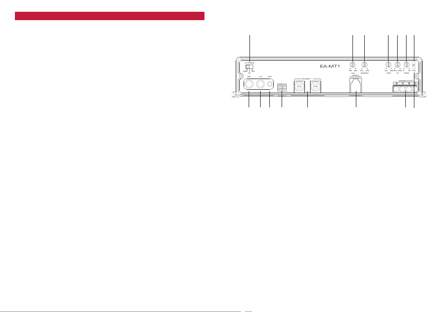
CONNECTIONS + CONTROLS EA-MT1
Control panel
1 Turn-On Mode
Slide switch to select the Auto-Turn-On function: Signal by music signal,
DC to switch on by DC offset signal of the head units integrated amplifier,
REM by remote wire.
2 INPUT GAIN CONTROL
Input gain potentiometer to match the output voltage of the head-unit to the amplifier’s
input.
3 SUBSONIC FREQUENCY CONTROL
Control potentiometer to adjust the crossover subsonic filtering frequency point of the
amplifier.
4 BASS BOOST
To inc rease bass per for mance fro m 0 – 15 dB @ 40 Hz.
5 LOWPASS FREQUENCY CONTROL
Control potentiometer to adjust the crossover lowpass filtering frequency point of the
amplifier.
6 PHASE SHIFT CONTROL
Control potentiometer for variable phase adjustment of the signal of the amplifier.
7 PROTECT LED
Protect state of amplifier is signaled by the red LED.
8 POWER LED
LED to show proper operating status of the amplifier by green illumination.
9 SPEAKER OUTPUT TERMINAL
Output terminal to connect the speakers to the amplifier.
10 REMOTE CONTROL
Port for the provided remote control (EA-MT1 only).
11 RCA INPUTS CH1/CH2
Low-level stereo RCA signal input CH1/CH2 for connection to the head-unit.
12 SPEAKER INPUT TERMINAL
Input terminal to connect the speaker cables of the head unit to the amplifier.
13 “REM” INPUT TERMINAL
Terminal to connect the amplifier to the automatic (remote) turn-on / turn-off lead of the
head unit.
1 2 3 4 5 6 7
bq bp bo bn bm bl 9 8
14 “+12V” POWER INPUT TERMINAL
Terminal to connect the amplifier to the positive +12V pole of the car battery.
15 “GND” POWER INPUT TERMINAL
Terminal to connect the amplifier to the chassis ground or negative pole of the car battery.
4 5
Page 4
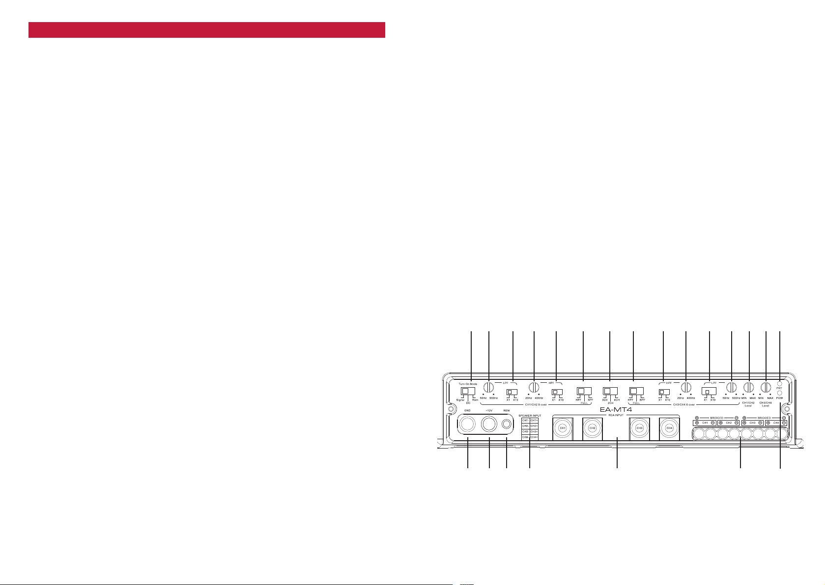
CONNECTIONS + CONTROLS EA-MT4
1 Turn-On Mode
Slide switch to select the Auto-Turn-On function: Signal by music signal,
DC to switch on by DC offset signal of the head units integrated amplifier,
REM by remote wire.
2 LOWPASS FREQUENCY CONTROL CH1/CH2
Control potentiometer to adjust the CH1/CH2 crossover lowpass filtering frequency
point of the amplifier.
3 LOWPASS FREQUENCY MULTIPLIER CH1/CH2
The x1 / x10 multiplier applies to the lowpass filtering frequency point of the amplifier.
4 HIGHPASS FREQUENCY CONTROL CH1/CH2
Control potentiometer to adjust the CH1/CH2 crossover highpass filtering frequency
point of the amplifier.
5 HIGHPASS FREQUENCY MULTIPLIER CH1/CH2
The x1 / x10 multiplier applies to the highpass filtering frequency point of the amplifier.
6 CROSSOVER MODE
Switch to choose between Highpass (HPF), full signal (FULL) and Bandpass (BPF)
filter. The BPF filter works with both highpass and lowpass filter.
7 INPUT CHANNEL MODE
The in put channel switch makes the amp lif ier funct ional on all ch annels using 2, 3 or 4
RCA inputs.
8 CROSSOVER MODE CH3/CH4
Switch to choose between Highpass (HPF), full signal (FULL) and Bandpass (BPF)
filter. The BPF filter works with both highpass and lowpass filter.
9 HIGHPASS FREQUENCY MULTIPLIER CH3/CH4
The x1 / x10 multiplier applies to the highpass filtering frequency point of the amplifier.
10 HIGHPASS FREQUENCY CONTROL CH3/CH4
Control potentiometer to adjust the CH3/CH4 crossover highpass filtering frequency
point of the amplifier.
11 LOWPASS FREQUENCY MULTIPLIER CH3/CH4
The x1 / x10 multiplier applies to the lowpass filtering frequency point of the amplifier.
12 LOWPASS FREQUENCY CONTROL CH3/CH4
Control potentiometer to adjust the CH3/CH4 crossover lowpass filtering frequency
point of the amplifier.
13 INPUT GAIN CONTROL CH1/CH2
Input gain potentiometer to match the output voltage of the head-unit to the amplifier’s
input.
14 INPUT GAIN CONTROL CH3/CH4
Input gain potentiometer to match the output voltage of the head-unit to the amplifier’s
input.
15 PROTECT LED
Protect state of amplifier is signaled by the red LED.
6 7
16 POWER LED
LED to show proper operating status of the amplifier by green illumination.
17 SPEAKER OUTPUT TERMINALS
Output terminals to connect the speaker cables to the amplifier.
18 RCA INPUTS
Low-level stereo RCA signal input CH1/CH2 and CH3/CH4 for connection to the head-
unit.
19 SPEAKER INPUT TERMINAL
Input terminal to connect the speaker cables of the head unit to the amplifier.
20 “REM” INPUT TERMINAL
Terminal to connect the amplifier to the automatic (remote) turn-on / turn-off lead of the
head unit.
21 “+12V” POWER INPUT TERMINAL
Terminal to connect the amplifier to the positive +12V pole of the car battery.
22 “GND” POWER INPUT TERMINAL
Terminal to connect the amplifier to the chassis ground or negative pole of the car
battery.
Control panel
1 2 3 4 5 6 8 bl bn7 9 bm bo bp bq
cn cm cl bu bt bs br
Page 5

SPEAKER IMPEDANCE & POWER WIRE INFO
WIRE ROUTING
It is recommended that you follow the optimum speaker / subwoofer impedance info sug-
gested below.
EA-MT1 → 4/2 ohms mono
EA-MT4 → 4/2 ohms stereo / 4 ohms mono bridged
AMPLIFIER MOUNTING
Attention! For your own safety, disconnect the negative battery terminal (GND) or remove the main fuse in the positive power cable near the car battery, before you start
any wiring work!
Before you proceed to install this EMPHASER amplifier, it is recommended to map out the
complete sys t e m an d th e re s p e c t i v e wi r i n g re q u i r e d . Co n s i d e r al l ad d i t i o n a l el e c trical require -
ments and accessories, such as power cables, interconnect cables etc., to complete the install.
Please note that - because of possible interference problems with the existing car electrics
and electronics - especially the routing of the signal cables and the chassis ground connection will have a profound impact on the trouble-free (noise free!) operation of the amplifier.
The mounting location should be carefully selected and in the interest of passive driver and
passenger safety, the amplifier must be securely mounted. Make sure that there is no wiring
harness, fuel tank etc. behind or below the mounting surface that may be damaged by the
drilling of the holes for the amplifier mounting screws. After installation, there should be a
clearance of at least 5cm to all sides including the top of the amplifier heatsink. Make sure
the unit is not exposed to direct sunlight, humidity, water, oil or spill of other fluids that may
enter the amplifier.
Once the location where the amplifier will be mounted is defined, use the unit as a template
for the ma r king of th e mo u n t i n g ho l e s wi t h pe n c i l or fe l t - t i p ma r k e r. Th e mo u n t i n g ho l e s sh o u l d
be pilot-drilled, using a 2,0 mm or 2,5 mm drill bit. Bolt the amp down.
Important! There must not be a direct contact of the amplifier heatsink, bottom panel
or any other metal part of the amplifier to the vehicle metal panel! Electrical groundloops will cause audible hum!
MAIN POWER WIRES
We recommend a minimum main power cable cross-section (5m total length) of 20 mm² (based
on pure copper cable), for both the positive and the ground wires. Following these recommendations guarantees a trouble-free operation of your amplifier, as well as full power output.
Run the positive main power cable („+12V“) directly from the positive terminal of the car battery to the amplifier. For protection of your car audio system against electrical fire hazards,
resulting from a shor t-circuit of the main power cable to chassis ground a main fuse holder
must be inserted within the first 30 cm of the positive main power cable. . The applicable fuse
value must be matched to the limitations of your main power cable AND the current draw of
the amplifier – therefore choose an appropriate fuse value. For a 20 mm² copper cable we
recommend a 60 Ampere M- A NL fuse.
Attach the ground cable to the amplifier. In most cases it will be best to keep the ground cable
(„GND“) as short as possible, i.e. to find a chassis contact ver y close to the amplif ier. The
ground po w e r wi r e must have th e sa m e cr o s s -section as the positive po w e r ca b l e . Th e co n t a c t
point where the ground wire is attached to, must be solid and clean, i.e. free from rust or paint!
Tighten both power input terminals of the amplifier, and double check for perfect fit of both
main cable leads!
RCA & REMOTE WIRES
For best interference free transmission of the music signal, use double or triple shielded RCA
interconnects only. Twisted pair Interconnects offer excellent noise rejection as well. Route the
RCA interconnects away from potential sources of Interference, such as engine computers,
gas pumps, etc.
Carefully run the audio signal interconnects, the remote wire and – if applicable– the cable of
the bass level remote control from the head unit or dashboard to the amplifier. As mentioned
before, the audio signal cables should always be routed completely separate from the power
cables. Connect the remote (turn on/turn off) lead to the respective input terminal of the amplifier and to the remote output of your head-unit. Now you can connect the RCA interconnects
to the respective outputs of your head-unit and to the inputs of the amplifier. Pay attention to
connect the stereo interconnects correspondingly, left is 1CH and right is always 2CH a.s.o.
LOUDSPEAKER WIRES
For longer distances to the speakers, it is best to use 2.5 mm² or 4 mm² speaker cables to
avoid a loss of power or risk degradation of the signal quality.
Once the speaker cables have been routed, turn loose the screws of the speaker terminal,
insert the stripped and bare speaker cable ends and re-tighten the screws. Maintain correct
polarity („+“ to „+“; „-„ to „-„).
Close the electrical circuit by attaching the ground wire to the battery and switch on your
head unit. The green status LED should turn on. If the status LED does not illuminate or the
red protect LED lights up, your installation is wrong! Immediately turn off your head-unit and
carefully re-check all installation and wiring steps!
8 9
Page 6
CROSSOVER ADJUSTMENTS
For the amplif ier to perfor m best with your speakers, the electronic crossover controls must
be set and adjusted accordingly.
SELECTING THE OPERATION MODE
You must select and set the appropriate operation mode before you can proceed to adjust
crossover frequency points. This operation mode depends on the speaker system connected
to the respective amplifier channels.
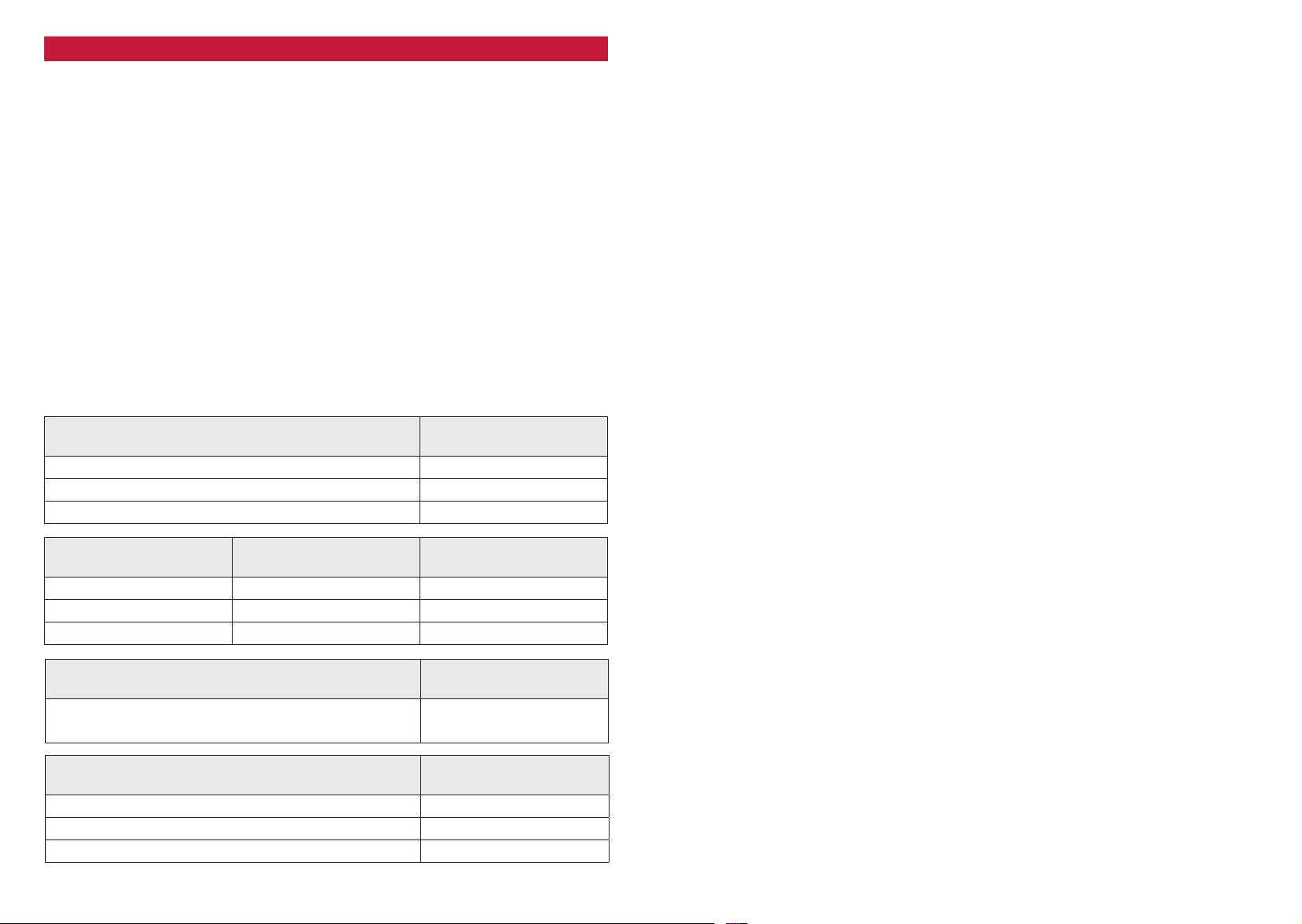
→ Select HPF if the speaker system is a component-, coaxial- or triaxial- type.
→ Select BPF in case of a midrange, kickbass or a subwoofer system.
→ Select Crossover "FULL" if your speaker system will handle a full range signal without
electrical or mechanical overload.
CROSSOVER FREQUENCY ADJUSTMENT
For satellite speaker systems, select the “HPF” mode, to cut off the bass content in the music
signal. Highpass filtering will take away unnecessary mechanical and electrical ‘strain’ from
the connected speaker systems. Depending on cone sur face, voice-coil diameter and the
power handling of the speakers, the following recommendations can be issued:
FRONT DOOR SATELLITE
SPEAKER SYSTEM PASSIVE
10 cm 2-way Coaxial or Component System 20 0 - 300 Hz
13 cm 2-way Coaxial or Component System 80 - 110 Hz
16 cm 2- or 3-way Component System 50 - 80 Hz
MIDRANGE SPEAKER
SETTING (ACTIVE)
HP CROSSOVER
FREQUENCY
10 cm Midrange 200 - 30 0 Hz 3000 – 5000 Hz
13 cm Midrange 80 - 110 Hz 3000 – 5000 Hz
16 cm Midrange 50 - 80 Hz 3000 – 5000 Hz
TWEETER
SETTING (ACTIVE)
The result of Resonance Frequency Fs x 2
is the minimum crossover frequency
HP CROSSOVER
FREQUENCY
LP CROSSOVER
FREQUENCY
LP CROSSOVER
FREQUENCY
3000 – 5000 Hz
SUBWOOFER CROSSOVER FREQUENCY ADJUSTMENT
Select “BPF”, to activate the lowpass filter of the integrated electronic crossover. The lowpass
cut-off frequency setting depends on the woofer system and each vehicle is different! As a
rule of thumb, settings in between 60 to 90 Hz will usually give solid results for subwoofers.
Set the EA-MT4 “HPF” to the minimum at 20 Hz for 10” or 12” subwoofer and 30 Hz or higher
for smaller subwoofer. The EA-MT1 Subsonic filter can be set to 5 Hz – 20 Hz for 10” or 12”
woofers and 30 Hz or higher for smaller subwoofer. The woofer lowpass and highpass frequency
points are mostly a matter of taste, and must therefore be ‘played by ear’.
INPUT GAIN ADJUSTMENT
To reach a maximum in dynamic response from each individual head-unit/amplifier/speaker
combination, it is important to set the respective input sensitivity controls („GAIN“) of all chan-
nel pairs correctly.
Before you start, you MUST set all tone controls (Bass, Mid, Treble, Loudness etc.) and the
fader on the head unit to their neutral or center positions.
Now tur n all input gain controls of the installed amplifiers anti- clock wise to their minimum
positions and start with the channel pair that drives the subwoofer system.
SUBWOOFER CHANNEL(S)
Set the volume control of your head-unit to approximately ¾ of full volume, while playing a
dynamic piece of music. Slowly increase the input gain control of the channel pair driving the
subwoofer(s), by turning the GAIN control clockwise. Increase clockwise until the bass starts
to di s t o r t. Re d u c e th e ma i n volume leve l of your head - u n i t to a medium liste n i n g le vel. Proceed
with further channels, if applicable.
SATELLITE CHANNELS
Slowly increase the input gain control of the channel pair driving the satellite system, by turning
the GAIN control clock wise. Increase clock wise until you reach a good tonal balance with a
slight emphasis of the bass range. Repeat for all further channels.
FINE TUNING OF ALL CROSSOVER FREQUNCY POINT SETTINGS
Finally you can attempt to fine-tune the H.P.F. and/or the LPF crossover frequencies on your
amplifier setup, to reach the maximum tonal balance and channel integration of all loudspeakers connected to your car audio system.
REAR SATELLITE
SPEAKER SYSTEM
HP CROSSOVER
FREQUENCY
10 cm 2-way Coaxial or Component System 120 - 140 Hz*
13 cm 2-way Coaxial or Component System 110 - 130 Hz*
6x9” or 7x10” Triaxial Speaker System 100 - 120 Hz*
* When a subwoo fer is par t of th e audio system instal l.
10 11
Page 7
Wir danken Ihnen für den Kauf dieser unvergleichlichen EMPHASER Endstufe.
Damit Sie die Wiedergabequalität und die Leistungsfähigkeit dieses Verstärkers voll ausschöpfen können, bitten wir Sie, sich eingehend mit den Möglichkeiten und technischen Features
dieses Verstärkers vertraut zu machen. Lesen Sie deshalb die nachfolgenden Abschnitte
sorgfältig durch und bewahren Sie diese Bedienungsanleitung auf.
Falls Sie im Anschluss weitergehende Fragen zu den Funktionen oder dem Anschluss dieser
Enstufe haben, kontaktieren Sie ihren Händler.
HAUPTMERKMALE
EA-MT1
■ 1-CH Endstufe für 4/2 Ohm Mono Lautsprecherimpedanz
■ Einstellbare 12 dB/Okt. TP + Subsonic Frequenzweiche
■ Bass Boost
■ Inklusive Basspegel-Fernbedienung
■ Umfangreiche Schutzschaltung
EA-MT4
■ 4-CH Endstufe für 4/2 Ohm Stereo Lautsprecherimpedanz
■ Brückenbetrieb an 4 Ohm
■ Einstellbare 12 dB/Okt. HP und BP Frequenzweiche
■ Erweiterter Frequenzweichenbereich für 2-Wege Aktiv-Setup
■ Umfangreiche Schutzschaltung
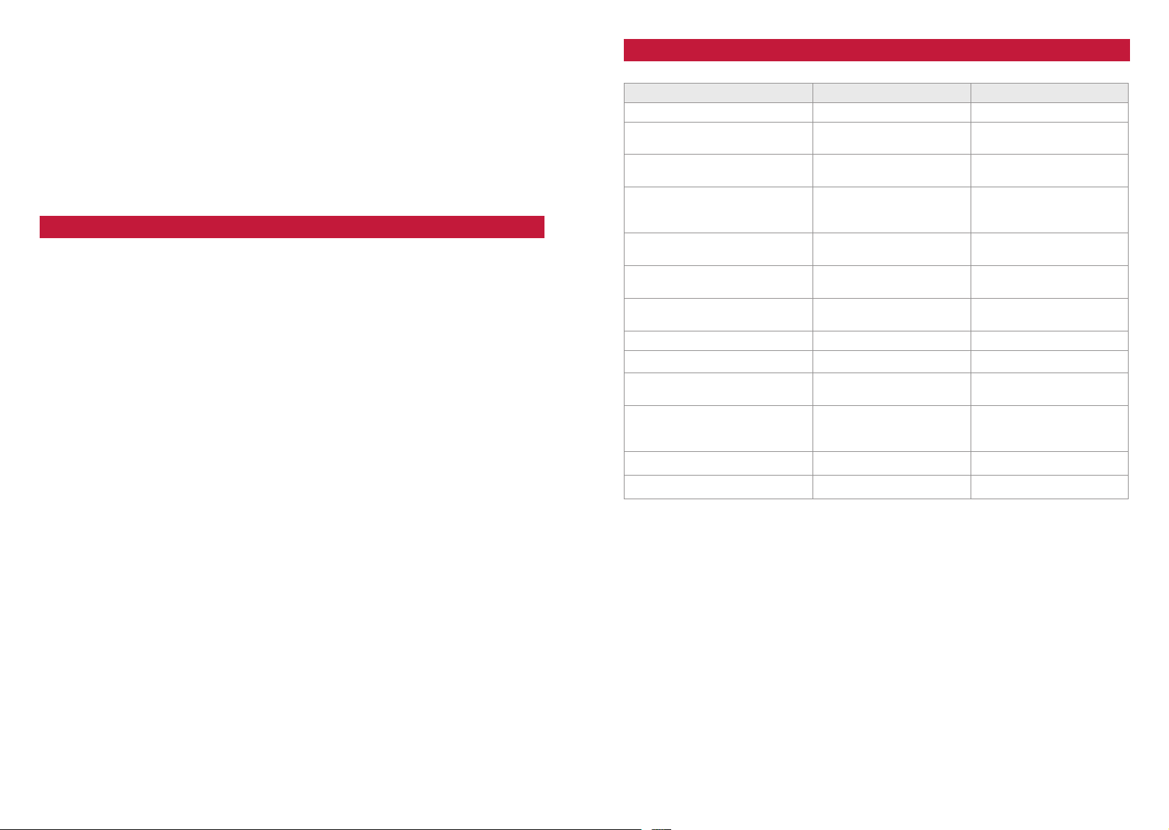
TECHNISCHE SPEZIFIKATIONEN
Model EA-MT1 EA- MT4
Number of Channels 1 4
Rated Power Output (RMS)
At 4 Oh ms / 14.4V (TH D <=0 .1%)
Rated Power Output (RMS)
At 2 Ohms / 14. 4V (TH D<=1.0%)
Rated Power Output (RMS)
Bridged, 4 Ohms / 14.4V
(TH D <=1.0 %)
Damping Factor
4 Ohms/100Hz
Signal-to-Noise Ratio
(All channels)
Frequency Response
(x-over set to FULL)
Channel Separation n.a. > 60 dB
Input Sensitivity 0.35 – 10 V 0.35 – 10 V
Integrated X-Over
Slope Rat es HPF / LP F
Cross-Over Frequency:
High Pass
Low Pass
Maximum Current Draw 70 A 70 A
Dimensions (W x H x D) 212 x 35 x 110 mm 212 x 35 x 110 mm
45 0 W x 1 100 W x 4
60 0 W x 1 150 W x 4
n.a. 320 W x 2
> 40 0 > 40 0
> 90 dB > 90 dB
10 Hz - 50 0 Hz 10 Hz - 40 kHz
12 dB/Oct. 12 dB/Oct.
15 - 40 Hz
50 - 50 0 Hz
20 - 4000 Hz
50 - 50 00 Hz
12 13
Page 8
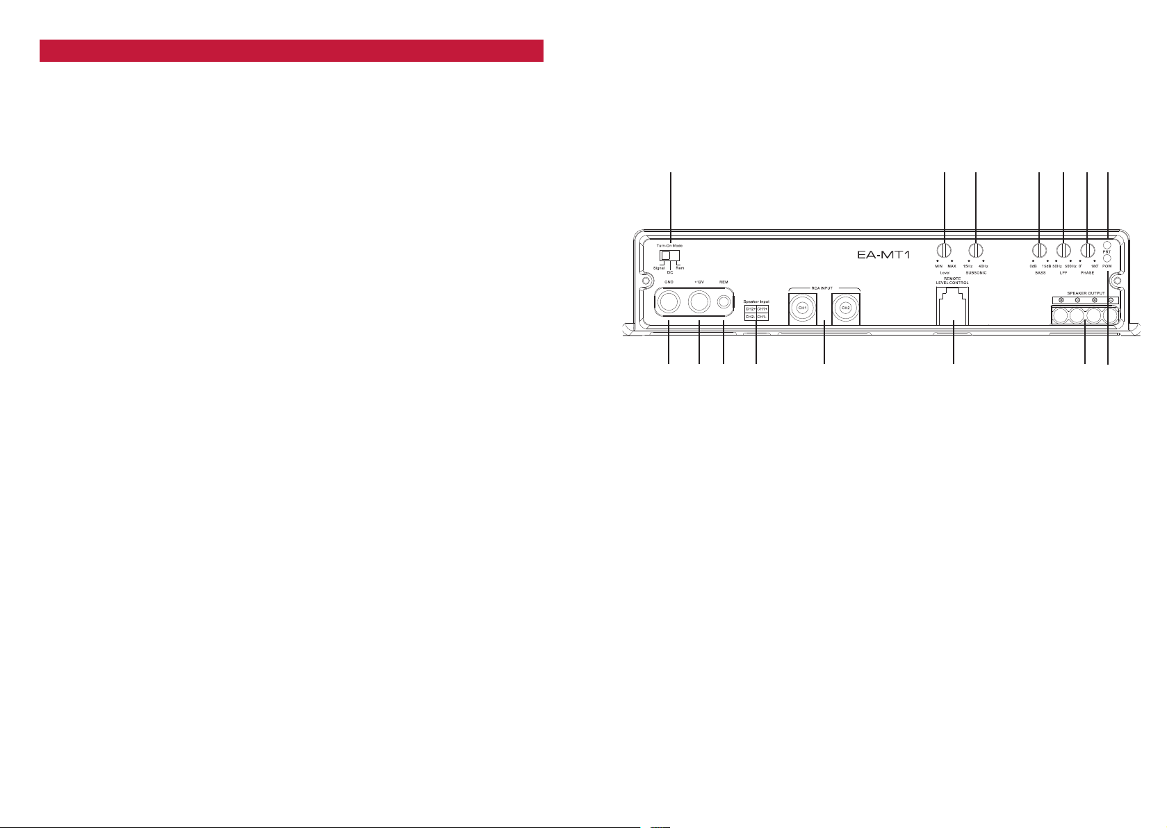
ANSCHLÜSSE + BEDIENUNGSELEMENTE EA-MT1
EINGÄNGE + AUSGÄNGE
1 EINSCHALT-MODUS
Schalter zum Auswählen der Auto-Turn-On Funktion: Signal für Musiksignal, DC zum
Einschalten durch das DC Offset Signal des Autoradios, REM für Remote-Kabel.
2 REGLER EINGANGSEMPFINDLICHKEIT CH1/CH2
Eingangsempfindlichkeitsregler „GAIN“ der Kanäle CH1/CH2, für die Anpassung an
die Ausgangsspannung des Steuergerätes.
3 SUBSONIC REGLER
Regler „Subsonic“ zum Einstellen der Hochpass-Trennfrequenz an der integrierten
elektronischen Frequenzweiche des Ausgangskanals.
4 BASS BOOST
Erhöht die Bassleistun g um 0 – 15 dB @ 40 Hz.
5 LOWPASS REGLER
Regler „LPF“ zum Einstellen der Tiefpass-Trennfrequenz an der integrierten
elektronischen Frequenzweiche des Ausgangskanals.
6 PHASE SHIFT REGLER
Stufenloses Einstellen der Phasenlage des Ausgangssignals.
7 PROTECT LED
Signalisiert durch rotes Leuchten die aktivierte Schutzschaltung.
8 POWER LED
Signalisiert den normalen Betriebszustand der Endstufe im eingeschalteten Zustand
durch grünes Leuchten.
9 LAUTSPRECHER AUSGANGSTERMINAL
Terminal für den Anschluss des Subwoofers.
10 REMOTE LEVEL CONTROL
Eingangsbuchse für die beiliegende Basspegel-Fernbedienung (nur EA-MT1)
11 RCA INPUTS CH1/CH2
Cinch Eingangsbuchsen CH1/CH2 für den Anschluss der Cinch-Ausgänge des
Steuergerätes.
12 LAUTSPRECHER INPUT CH1/CH2
Lautsprechereingänge CH1/CH2 für den Anschluss an die Lautsprecherkabel des
Steuergerätes.
13 „REM“ INPUT TERMINAL
Eingangsterminal für den Anschluss des Remote-Kabels über den Amp- oder
Antenna-Remote Ausgang des Steuergerätes.
14 „+12V“ POWER INPUT TERMINAL
Eingangsterminal für den Anschluss an den Pluspol der Fahrzeugbatterie.
15 “GND“ POWER INPUT TERMINAL
Eingangsterminal für den Anschluss an die Chassis-Masse des Kfz’s, oder den
Minuspol der Fahrzeugbatterie.
Control panel
1 2 3 4 5 6 7
bq bp bo bn bm bl 9 8
14 15
Page 9
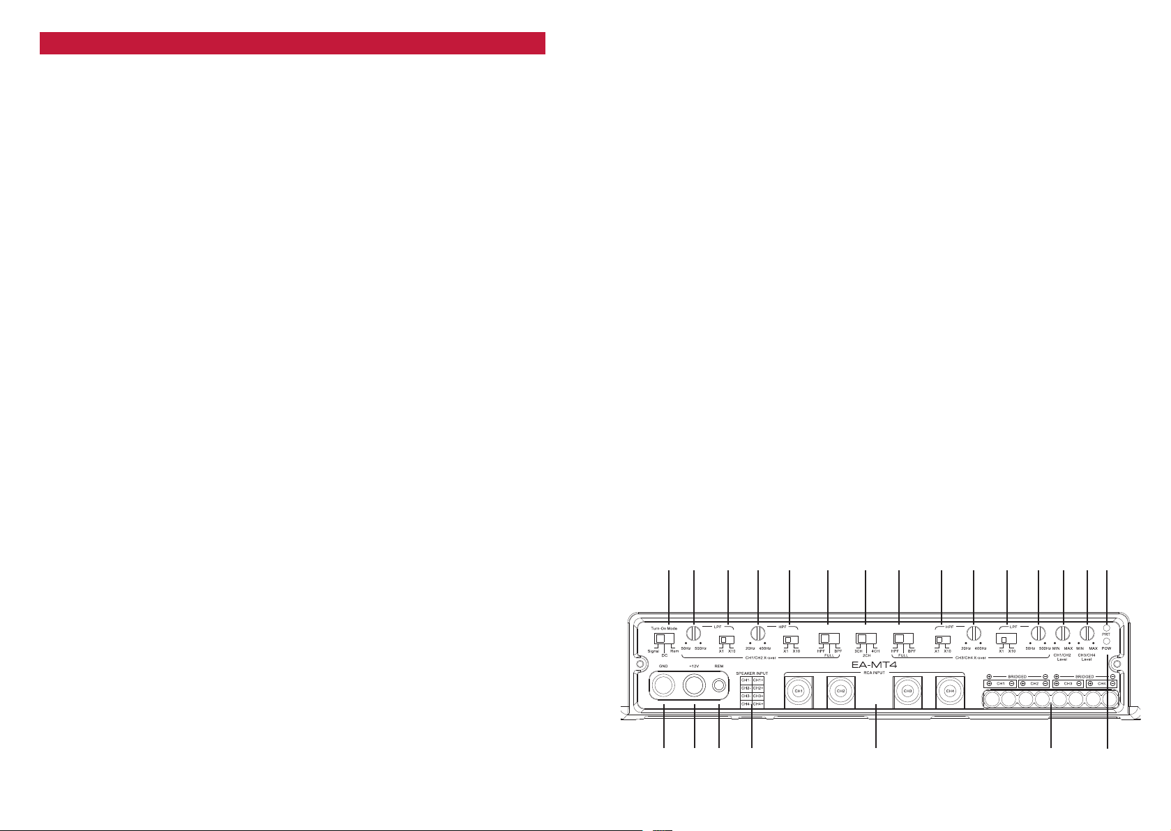
ANSCHLÜSSE + BEDIENUNGSELEMENTE EA-MT4
EINGÄNGE + AUSGÄNGE
1 EINSCHALT-MODUS
Schalter zum Auswählen der Auto-Turn-On Funktion: Signal für Musiksignal, DC zum
Einschalten durch das DC Offset Signal des Autoradios, REM für Remote-Kabel.
2 LOWPASS REGLER CH1/CH2
Regler „LPF“ zum Einstellen der Tiefpass-Trennfrequenz an der integrierten
elektronischen Frequenzweiche der Ausgangskanäle CH1/CH2.
3 LOWPASS MULTIPLIKATOR CH1/CH2
Multipliziert die Tiefpass-Trennfrequenz der integrierten elektronischen
Frequenzweic he um den Faktor x1 ode r x10.
4 HIGHPASS REGLER CH1/CH2
Regler „HPF“ zum Einstellen der Hochpass-Trennfrequenz an der integrierten
elektronischen Frequenzweiche der Ausgangskanäle CH1/CH2.
5 HIGHPASS MULTIPLIKATOR CH1/CH2
Multipliziert die Hochpass-Trennfrequenz der integrierten elektronischen
Frequenzweic he um den Faktor x1 ode r x10.
6 X-OVER MODUS CH1/CH2
Legt die Funktionsweise der integrierten Frequenzweiche fest: Hochpassfilter (HPF,
volles Signal (FULL) oder Bandpass (BPF).
7 EINGANGSWAHLSCHALTER
Falls nur ein Stereo-Cinchkabel zur Verfügung steht, das Cinchkabel mit CH1/2
verbinden und Schalter auf „2-CH“ stellen, um das Eingangssignal intern zu den
Kanälen CH3/4 weiterzuleiten.
Falls Sie drei Cinchkabel zu Verfügung haben (CH1/CH2 und ein Subout), stellen Sie
den Schalter auf „3“ und stecken das Subwoofer Cinchkabel in den RCA Eingang CH3.
Wenn alle vier RCA-Eingänge belegt werden, Schalter auf „4-CH“ stellen.
8 X-OVER MODUS CH3/CH4
Legt die Funktionsweise der integrierten Frequenzweiche fest: Hochpassfilter (HPF,
volles Signal (FULL) oder Bandpass (BPF).
9 HIGHPASS MULTIPLIKATOR CH3/CH4
Multipliziert die Hochpass-Trennfrequenz der integrierten elektronischen
Frequenzweic he um den Faktor x1 ode r x10.
10 HIGHPASS REGLER CH3/CH4
Regler „HPF“ zum Einstellen der Hochpass-Trennfrequenz an der integrierten
elektronischen Frequenzweiche der Ausgangskanäle CH3/CH4.
11 LOWPASS MULTIPLIKATOR CH3/CH4
Multipliziert die Tiefpass-Trennfrequenz der integrierten elektronischen
Frequenzweic he um den Faktor x1 ode r x10.
12 LOWPASS REGLER CH3/CH4
Regler „LPF“ zum Einstellen der Lowpass-Trennfrequenz an der integrierten
elektronischen Frequenzweiche der Ausgangskanäle CH3/CH4.
13 REGLER EINGANGSEMPFINDLICHKEIT CH1/CH2
Eingangsempfindlichkeitsregler „GAIN“ der Kanäle CH1/CH2, für die Anpassung an
die Ausgangsspannung des Steuergerätes.
14 REGLER EINGANGSEMPFINDLICHKEIT CH3/CH4
Eingangsempfindlichkeitsregler „GAIN“ der Kanäle CH3/CH4, für die Anpassung an
die Ausgangsspannung des Steuergerätes.
15 PROTECT LED
Signalisiert durch rotes Leuchten die aktivierte Schutzschaltung.
16 POWER LED
Signalisiert den normalen Betriebszustand der Endstufe im eingeschalteten Zustand
durch grünes Leuchten.
17 LAUTSPRECHER AUSGANGSTERMINAL
Terminal für den Anschluss der Lautsprecher, stereo oder gebrückt.
18 RCA INPUT
Cinch Eingangsbuchsen CH1/CH2/CH3/CH4 für den Anschluss der Cinch Ausgänge
des Steuergerätes.
19 SPEAKER INPUT
Terminal CH1/CH2/CH3/CH4 für den Anschluss der Lautsprecherkabel des Steuergerätes.
20 „REM“ INPUT TERMINAL
Eingangsterminal für den Anschluss des Remote-Kabels über den Amp- oder
Antenna-Remote Ausgang des Steuergerätes.
21 „+12V“ POWER INPUT TERMINAL
Eingangsterminal für den Anschluss an den Pluspol der Fahrzeugbatterie.
22 “GND“ POWER INPUT TERMINAL
Eingangsterminal für den Anschluss an die Chassis-Masse des Kfz’s, oder den
Minuspol der Fahrzeugbatterie.
Control panel
1 2 3 4 5 6 8 bl bn7 9 bm bo bp bq
cn cm cl bu bt bs br
16 17
Page 10

LAUTSPRECHER IMPEDANZ & KABELINFO
VERKABELUNG / ELEKTRISCHER ANSCHLUSS
Die möglichen Abschlussimpedanzen ihres Verstärker Modells entnehmen Sie den
folgenden Angaben.
EA- MT1 → 4/2 Ohm Mon o
EA-MT4 → 4/2 Ohm Stereo / 4 Ohm Mono gebrückt
MONTAGE DES VERSTÄRKERS
ACHTUNG! Entfernen Sie zu Ihrer eigenen Sicherheit erst das Massekabel von der
Batterie!
Bei allen nachfolgend beschriebenen Installationsschritten muss der Stromkreis des Kraftfahrzeugs unterbrochen sein! Erst nach Abschluss aller Installationsarbeiten wird über das
Massekabel der Stromkreis wieder geschlossen.
Bevor Sie mit der Montage dieses Verstärkers beginnen: Berücksichtigen Sie vorab die
Kabelverläufe und den Installationsort.
Der Verstärker sollte im Interesse der Sicherheit bei einem Unfall möglichst gut und solide
montiert werden. Die Endstufe sollte auf keinen Fall „unzugänglich verbaut“ werden, wegen
der schlechten Kühlung und auch den abschliessend erfolgenden Einstellarbeiten.
Als Montageort eignet sich z.B. ein Platz im Kofferraum oder an einem Seitenteil, bzw jeder
andere Ort, der eine saubere Installation ermöglicht.
Vermeiden Sie Montageorte mit „unbekanntem Hintergrund“. Es könnten sich ein Benzintank,
hydraulische Bremsleitungen, Kabelbäume etc. dahinter verbergen! Achten Sie auch auf einen
trocken, gegen mechanische Einwirkungen geschützten Installationsort.
Halten Sie den Verstärker an den gewünschten Ort und markieren Sie mit einem geeigneten
Filzstift die Bohrposition der Befestigungslöcher.
Mit der gebotenen Vorsicht bohren Sie nun die angezeichneten Löcher mit einem 2,0 mm
oder 2,5 mm Bohrer.
ACHTUNG: Die Endstufe darf niemals direkt auf die Fahrzeugmasse des Kfz’s geschraubt
werden da eine Masse-Brummschleife resultiert! Legen Sie nun den Verstärker auf die
vorgebohrten Löcher und schrauben Sie ihn gut fest.
HAUPT-STROMKABEL
Wir empfehlen einen minimalen Kabelquerschnitt (bei einer Länge von 5 m) von 20 mm²
(bezogen auf reines Kupfer kabel) für das +12V und das Massekabel. Diese Empfehlung
garantiert eine problemlose Funktion des Verstärkers, sowie volle Leistungsabgabe ohne
übermässige Erwärmung.
Verlegen Sie das Pluskabel direkt von der Batterie zum Verstärker. Innerhalb der ersten
30 cm nach dem Pluspolklemmenabgriff muss eine Hauptsicherung angebracht werden
(Absicherung des Pluskabels gegen Kurzschluss auf Fahrzeug-Masse und dadurch resul tierendem Kabelbrand!). Verwenden Sie einen dem Stromkabelquerschnitt entsprechenden
Sicherungswert. Wir empfehlen bei 20 mm² Kupferkabel eine 60 A M-ANL Sicherung.
Schliessen Sie das Masse-Powerkabel am Verstärker und an einem geeigneten Massepunkt
im Fahrzeug an. Versuchen Sie das Massekabel so kurz wie möglich zu halten. Es sollte
denselben Querschnitt wie das positive Powerkabel besitzen. Achten Sie beim Massepunkt
auf eine perfekt gesäuberte blanke Metalloberfläche im Fahrzeug (schlechte Massepunkte
sind sehr oft die Ursache für Störungen).
CINCH- & REMOTE KABEL
Verwenden Sie für beste Einstörfestigkeit am besten doppelt oder dreifach abgeschirmte Kabel,
oder sogenannte „Twisted Pair“ Typen. Die Signalführenden Cinchkabel sollten soweit als
möglich von allen potentiellen „elektrischen Störsendern“ wie Bordcomputer, Benzinpumpe,
Blac k Boxes, etc. verle gt werden.
Verlegen Sie das oder die Cinchkabel, das Fernbedienungskabel für die Pegel-Regelung
(falls gewünscht) und das Remote-Kabel vom Steuergerät zur Endstufe.
Diese Kabel sollten unbedingt räumlich getrennt von der Stromzuführung des Verstärker s
eingezogen werden. Schliessen Sie das Remote-Kabel an das mit „REM“ bezeichnete Terminal
an der Endstufe und an das mit Antenna-Rem. oder Amplifier-Rem. bezeichnete Kabel Ihres
Steuergerätes an. Anschliessend stecken Sie die Cinchkabel in die Cinchbuchsen am Verstärker
ein. Beachten Sie hierbei die Seitenkennung, d.h. CH1 ist links, CH2 ist rechts, etc.!
Nun wird – falls erwünscht – noch die Fernbedienung in Griffnähe angebracht und der Stecker
vom Kabel in die Buchse am Verstärker eingesteckt.
LAUTSPRECHERKABEL
Verwenden Sie qualitativ gutes Lautsprecherkabel mit einem minimalen Querschnitt von
2.5 mm² bis 4 mm ². Bei größeren Längen um 5 m können Kabelquerschnitte bis zu 6 mm²
durchaus Sinn machen.
Schliessen Sie nun die Lautsprecherkabel an. Entfernen Sie ca. 6-8 mm der Isolierung des
LS-Kabels und beachten Sie die richtige Polung der Lautsprecherkabel am Terminal ("+" auf
"+", "-" auf "-"). Ziehen Sie die LS-Schraubklemmen satt an.
Schliessen Sie den Stromkreis zum Verstärker durch Remontage der Massepolklemme an
der Batterie. Ihr Verstärker sollte beim Einschalten des Steuergerätes durch das Aufleuchten
der grünen LED Betriebsbereitschaft anzeigen. Leuchtet die grüne LED nicht oder leuchtet
sogar die rote "Protect" LED, ist Ihre Installation fehlerhaft. Gehen Sie die gesamten Installationsanweisungen und die Verkabelung nochmals genau durch.
18 19
Page 11
EINSTELLUNG DER FREQUENZWEICHE
Damit der Verstärker die angeschlossenen Lautsprechersysteme optimal ansteuern kann,
müssen Sie die Einstellungen an der Frequenzweiche vornehmen.
WAHL DES BETRIEBSMODUS
In Abhängigkeit der im Fahrzeug verbauten Lautsprechersysteme müssen Sie jedes Kanalpaar
über den Betriebswahlschalter konfigurieren. Jedes Kanalpaar ermöglicht die Wahl eines
Hoch- oder Bandpass-Betriebs der nachfolgenden Verstärkerkanäle.
Die Hochpass oder Tiefpass Funktion teilt den eingesetzten Lautsprechersystemen nur
den Frequenzbereich zu, den der Lausprecher verarbeiten kann. Beachten Sie folgende
Empfehlungen:
→ Wähl en Si e den Hochpass „HPF”, wenn der angeschlossene Lautsprecher ein Koax-,
Triax- oder Komponenten Lautsprecher ist.
→ Wähl en Si e Bandpass “BPF”, wenn der angeschlossene Lautsprecher ein Tieftö ner
oder Subwoofer System ist.
→ Wählen Sie "FULL", wenn der angeschlossene Lautsprecher den gesamten
Frequenzbereich ohne Filterung verarbeiten kann.
EINSTELLUNG DER FREQUENZWEICHE
Mit der Einstellung der Trennfrequenz des Hochpasses („HPF“) soll eine elektrische und
mechanische Entlastung der verwendeten Koax- oder Komponentensysteme erfolgen. Je
nach der vorhandenen Membranfläche und Nennbelastbarkeit der verwendeten (Satelliten)Systeme wird eine Trennfrequenz um 50 bis 150Hz die besten Resultate zeigen.
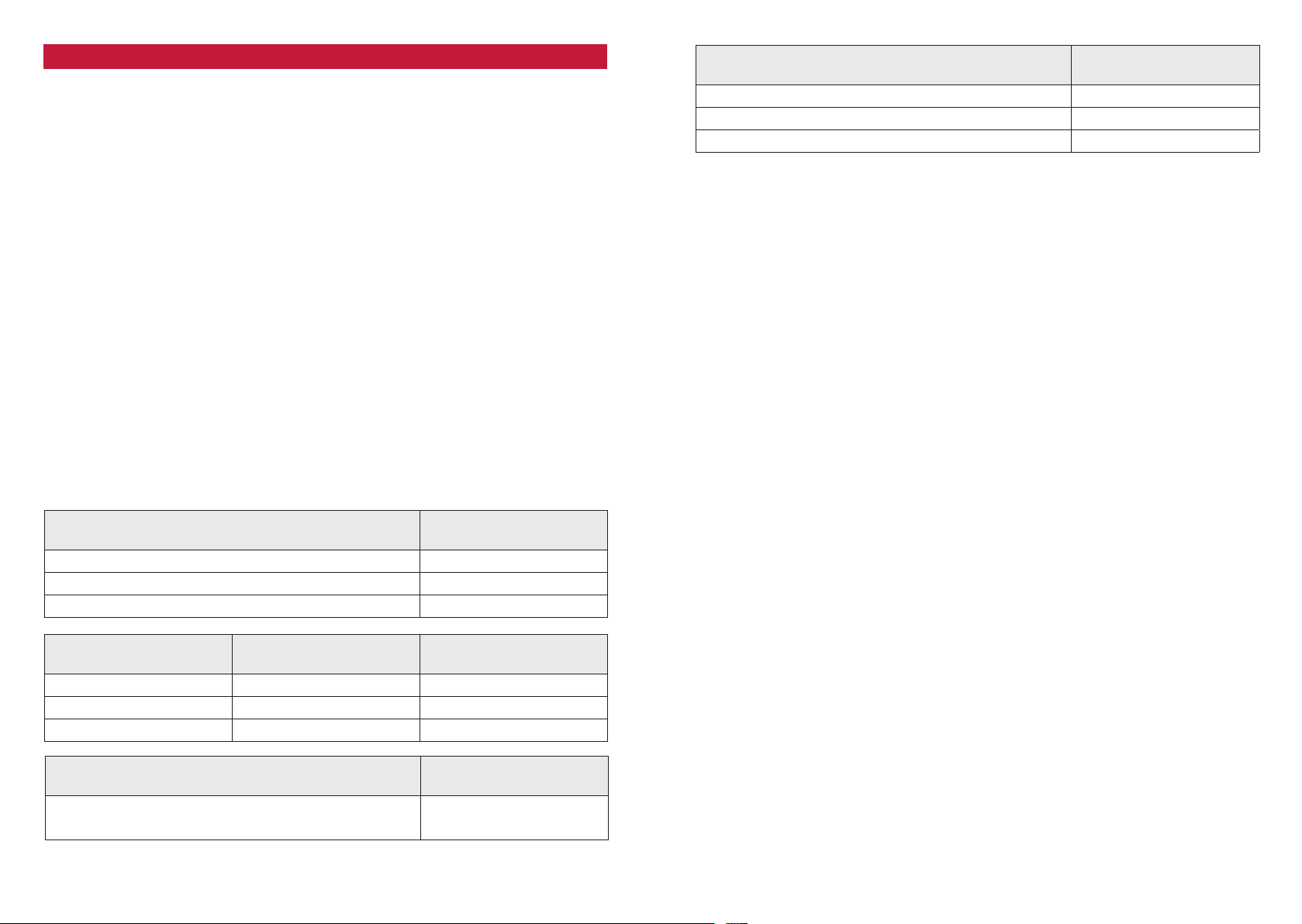
FRONTTÜREN LAUTSPRECHERSYSTEM
PASSIV
10 cm 2-Wege Koaxial oder Komponentensystem 20 0 - 300 Hz
13 cm 2-Wege Koaxial oder Komponentensystem 80 - 110 Hz
16 cm 2- oder 3-Wege Komponentensystem 50 - 80 Hz
TIEL-/MITTELTÖNER
SYSTEM AKTIV
HPF
TRENNFREQUENZ
10 cm Mitteltöner 20 0 - 300 Hz 3000 – 5000 Hz
13 cm Tief-/Mitteltöner 80 - 110 Hz 3000 – 5000 Hz
16 cm Tief-/Mitteltöner 50 - 80 Hz 3000 – 5000 Hz
HOCHTÖNER
AKTIV
Resonanz-Frequenz Fs x 2 ergibt die minimale
Trennfrequenz
HPF
TRENNFREQUENZ
LPF
TRENNFREQUENZ
LPF
TRENNFREQUENZ
3000 – 5000 Hz
HINTERES
LAUTSPRECHERSYSTEM
HPF
TRENNFREQUENZ
13 cm 2-Wege Koaxial oder Komponentensystem 120 - 140 Hz*
16 cm 2-Wege Koaxial oder Komponentensystem 110 - 130 Hz*
6x9” or 7x10” Triaxial-Lautsprechersystem 100 - 120 Hz*
* Wenn ein Subwoo fer Teil des Car-Au dio Sys tems is t.
TIEFPASS TRENNFREQUENZ
Stellen Sie den Betriebswahlschalter auf „BPF“. Diese Einstellung erfolgt rein gehörmässig
und hängt von vielen Faktoren, wie Subwoofer-System und dem Fahrzeug selber ab. Als
Faustregel sollte die einzustellende Trennfrequenz des Tiefpasses (LPF) zwischen 50 bis
90 Hz liegen. Stellen Sie den HPF-Regler der EA-MT4 auf das Minimum 20 Hz for 25 cm
oder 30 cm Subwoofer und auf 30 Hz oder höher bei 20 cm Subwoofer. Stellen Sie den
HPF-Regler der EA-MT1 auf 5 – 20 Hz bei 25 cm oder 30 cm Subwoofer und auf 30 Hz oder
höher bei 20 cm Subwoofer. Die Subwoofer Tiefpass und Hochpass Abstimmung ist auch
eine Geschmackssache und sollte daher auch „nach Gehör“ geschehen.
EINGANGSEMPFINDLICHKEIT
Die korrekte Eingangsempfindlichkeitseinstellung ist wichtig für die Ausnutzung des optimalen Dynamikspielraumes der Steuergerät / Verstärker / Lautsprecherkombination. Die
Empfindlichkeitseinstellung beeinflusst das Grundrauschen ebenso, wie die verzerrungsfrei
erzielbare Maximallautstärke.
Bevor Sie mit der Anpassung der Eingangsempfindlichkeiten anfangen, müssen zuerst alle
Klangregler, sowie auch der Fader/Balance in die Mittel (Neutral) Position gebracht werden.
Deaktivieren sie auch die Loudness Funktion.
SUBWOOFER
Falls sich ein Subwoofer im Anlagenkonzept befindet, muss der Eingangs-GAIN als erstes
eingestellt werden. Drehen Sie den Input GAIN Regler an der Endstufe im Gegenuhrzeigersinn auf die Minimumposition. Stellen Sie den Lautstärkeregler Ihres Steuergerätes auf ca.
¾ der Maximallautstärke. Drehen Sie nun den GAIN Regler vom Subwoofer Kanal langsam
im Uhrzeigersinn auf, bis Sie die Verzerrungsgrenze im Bassbereich erreichen. Drehen Sie
nun die Laustärke vom Steuergerät auf ca. halb zurück und nehmen sie die Einstellung der
weiteren Kanalpaare vor.
LAUTSPRECHERSYSTEME
Stellen Sie den Lautstärkeregler Ihres Steuergerätes auf ca. ¾ der Maximallautstärke. Drehen Sie den GAIN Regler vom Kanalpaar der Frontsysteme langsam auf. „Dosieren“ Sie die
Lautstärke des vorderen Lautsprechersystems so hinzu, dass sich ein ausgewogener und
basskräftiger Klang einstellt. Fahren Sie mit weiteren Kanalpaaren fort, falls im Systemkon-
zept vorhanden.
Wenn die Input-Gain Einstellung an allen vorhandenen Kanalpaaren erfolgt ist, empfiehlt es
sich auch, die Trennfrequenzen nochmals fein einzustellen.
20 21
Page 12

WARRANTY CONDITIONS + LIMITATIONS
Wha t product s are covere d by EMPHA SER’s limi ted Warra nty?
The li mited War ranty (the “ Warranty ”) applies to EMPHASE R product s purchased from an aut hor ized dealer by end customer s in the European
Econo mic Area or S witz erland (“ Territo rial Scope” ).
Wha t is the validi ty period o f EMPHAS ER’s Warr anty?
Under t his Warr anty, EM PHAS ER warra nts, for a p eriod of 2 y ears, th at the pro duct is fre e from def ects in ma terial an d/or wor kmanshi p at the tim e
of the original pu rchase. This 2- year perio d commences o n the date of the or iginal purchase as per th e original invoice or un til receip t. If you have
purch ased the p roduct as a c onsumer, an d the defe ct is iden tified w ithi n the firs t six mon ths af ter the or iginal pu rchase (se e above), w e will ass ume
that t he defec t already ex isted a t the time o f purchase.
Who ca n claim under t he Warran ty?
EMP HASER g rants t he limite d Warrant y to natu ral person s only, who p urchased t he relevan t product p rimaril y for pers onal use.
Wha t is covered by t he Warran ty?
EMPHASER warrants that the pr oduct is free fro m defects in material and/or workmanship at the time of the original purchase. EMPH ASER does
not , however, pr ovide a war ranty c overing ev ery defe ct and damage t hat may occur. I t only cov ers the har dware comp onents o f the device , and in
no eve nt the sof tware u sed wit h the devic e, regardl ess if thi s was provi ded by EMP HASER o r the thir d-par ty vendor. T he Warran ty ther efore do es
not co ver the fol lowing ca ses, in par ticular :
• norm al wear and te ar (such as to sur faces and p rotect ive cover ings);
• super ficial dam age, such as scr atches, d ents, an d damaged pla stic, wor n or mechani cally defe ctive co nnectio ns;
• misu se, includi ng any trea tment re sultin g in physica l or super ficial damage , such as a cosme tic defe ct, to th e product ;
• damage caused by connect ing or using t he produc t for a purpose ot her than those specified, or a failure to observe t he operat ing and/or
installation instruct ions for the particular model;
• installation or use of th e product contr ary to the applicable t echnical standards, or the safe ty regulations in t he countr y in which t he product is
installed or used;
• damage caused through an unaut hor ized attemp ted repair, or an at tempted repair by someone other than a EMPHASE R aut horized service
partner;
• damage c aused by mod ificati ons to the pr oduct no t express ly autho rized by th e manufac turer;
• damage c aused by mal icious code ( “Soft ware Vi ruses”) o r by using so ftwar e not suppl ied with t he produc t or which was i ncorrec tly ins talled;
• use of t hird party vendor sof tware programs for editing, modif ying, adapting, or extending EMPHASE R’s authorized soft ware componen ts as
are ru n on the prod uct;
• use of t hird-p arty ve ndor firmw are/ope rating s ystem so ftwa re
• damage c aused by liq uids or chem icals of wha tever ty pe, and/ or excessi ve temper atures, m oistur e, or damp;
• accide nts, dro ps or other s uch effe cts of ex treme acce leratin g forces;
• damage c aused by li ghtni ng stri kes, ele ctros tati c charge, in correc t operat ing vol tage, wa ter, fire, f orce maje ure, inad equate ve ntila tion fo r other
reasons for which EMPHASER is not responsible;
• damage c aused by usi ng the devi ce outsi de of the defi ned speci fication s;
• damage c aused by usi ng the prod uct wit h other sy stems or de vices, w hich are not de signed to b e used wit h this pro duct;
• adjus tments or modi fications withou t EMPHA SER‘s prior w ritten approval, including product upgrades ex tending beyond t he specifications or
characteristics described in the operating manual;
• modi fication s of the product for the purpose of adapt ing i t to na tional or local technical nor ms or safety s tandards of countries for which the
prod uct was not e xpressl y designe d or manufac tured;
• usin g service o r spare par ts not pro duced or dis tribut ed by EMP HASER ;
• usin g the produc t in connec tion wit h accessor ies not app roved for u se with t his produc t;
EMPHASER , mor eover, does not war ran t (expressly, implicitly, statutoril y, or ot her wise) the quality, performance , reliabilit y or suitabili ty o f the
prod uct for a par ticular pu rpose exce pt as descr ibed, nor th e soft ware/ firmwar e install ed on the dev ice ex work s.
No war ranty se rvice w ill be prov ided, more over, if the m odel numbe r
/serial number/ UUID/product number on the product is changed, er ased , made illegible or removed. The same applies i f the r eceipt or in voice is
incomplete and/or illegible when presented.
Is EMP HASER li able for oth er defect s or damage?
EMPHASER w ill repair or replace products, o nly i f the y are covered by the terms of this Warran ty. EMPHASER is not liable f or any material or
intangib le loss or damage such as the price paid for the product, loss o f pro fit s, revenue, data, or r elating t o the enjoymen t of the product or
components associa ted w ith it, arising directly or indirectly under t his Warran ty or otherwise in relation to products or services. This likewise
applies to loss or damage r elating t o the impair ment or operational failure of the pr oduc t, or devices associa ted w ith it, caused by defect s or the
non- availab ilit y of the pr oduct du ring th e time it i s with E MPHA SER or E MPHA SER ’s serv ice part ner, as wel l as to peri ods of dow ntim e and busin ess
interruptions. In addition, EMPH ASER does not accept an y liability for shipmen t-related risks - such as the loss or destruction of the product - in
conne ction wi th the fu lfilmen t of the Warr anty.
Thi s disclaime r applies t o losses o f damage irr especti ve of the le gal basis , especiall y on the gro unds of neg ligence, o ther wro ngful con duct (to rts),
breac h of contra ct, expr ess or impl ied guaran tees, and s trict li abilit y (even if EM PHAS ER or its se rvice par tner has b een advis ed of the pos sibilit y
of such d amage occurr ing).
If these disclaimers are prohibited or limited under the applicable la w, EMPHASE R wil l limit it s Warranty and liability to the ex tent permis sible
under t he applicable regulations. For example, some nati onal laws pr ohibit the exclusion or limiting of damage s payable in connec tion with
negli gence, gro ss neglig ence, will ful wro ngdoing, d eceitf ul conduc t, and ot her such act s. For th e duratio n of this War ranty , all liabili ty tha t cannot
be excluded comple tely will be limite d to the ext ent permissible under the applicable law. L iabilit y under this Warrant y is limited to the price paid
for t he product . If the app licable la w only perm its high er limit s on any liabil ity, th is higher li mitat ion will app ly.
How do I ex ercise my War ranty r ights?
If you w ant to exe rcise you r entit lemen ts under t his Warra nty, pl ease cont act the au thori zed dealer w here the p roduct w as purchas ed, and pre sent
it wi th the or iginal cop y of the til l receipt or i nvoice. D o not retu rn any pro ducts to E MPHAS ER direc tly, oth erwis e our Warran ty obli gations c annot
be ful filled. Yo u will find t he name of the r elevant d ealer or res eller on you r proof of pu rchase.
Defecti ve devices sent by the au thorized dealer to the ser vice center, must also be accompanied by any access ories with a logical connection to
the ob served fa ult. This mean s, for example, t he navigat ion package o n an SD or microSD car d supplied or purchased w ith the device, if problems
or fun ctional e rrors wer e observ ed in connec tion wit h the navi gation fu nction .
How wil l EMPHAS ER fulfil it s Warran ty?
EMPHASER or its service part ner will choose to either repair or replace the p roduct or i ts de fective par ts co vered by the Warrant y, and assume
the co sts of ma terial and l abor in doin g so.
Repairs under the Warrant y mus t be carried out by EMP HA SER or it s aut horized serv ice partner. Pr oduc ts that ar e repaired or replaced may
cont ain new and /or refur bished co mponent s and device s. Compo nents th at are swap ped out wil l become the p ropert y of EMP HASER .
Will I in cur any cos ts in connec tion with t he Warran ty servi ce?
EMPHASER assum es the cost s of material and labor in connecti on with its War ranty service. T he Warrant y holder is respo nsible for t he costs o f
shipment and bear s the risks connected wit h the shipment (see above). If the product is found to be operating fault lessly, or t here is no warranty
ent itleme nt because t he warra nt perio d has expir ed or for any o ther reas on, EMP HASE R or its aut horize d servi ce partn er will be en titl ed to charge
a flat- rate inv estiga tion fee of € 30. 00.
Do thi s Warrant y affec t my statu tory or con tractu al rights?
This Warrant y is made voluntaril y by EMPHA SER, an d it will, in any cas e, extend your s tatut ory righ ts. As a con sumer, you remain f ully entitl ed to
your s tatu tory r ights, s uch as the s tatu tory gua rantee . This War ranty a lso has no ef fect w hatsoe ver on your c ontrac tual rig hts agai nst the r eseller.
You may co ntinue t o exercise t hese righ ts in full .
22 23
GARANTIE-BESTIMMUNGEN + EINSCHRÄNKUNGEN
Für we lche Produ kte gilt die b egrenzt e Herste llergara ntie von EM PHASER ?
Die begrenzte Herstellergaran tie (im Weiteren als „Garantie“ bezeichnet) gilt für Produkt e von EMPHA SER, die Endkunden im Europäischen Wir tschaftsraum oder der Schweiz („räumlicher Geltungsbereich“) von einem autorisier ten Fachhändler erwerben.
Für we lchen Zeit raum gewäh rt EMPH ASER die Gar antie?
Mit dieser Garantie gewährt EMPHASER für den Zeitraum von 2 Jahren, dass das Produkt zum Zeitpunkt des Ersterwerbs keine Material- und/oder Verarbeitungsfehler aufweist. Maßgeblich für den Beginn des 2-Jahres-Zeitraumes ist das Datum des Ersterwerbs gemäß Originalrechnung bzw. des Kassenbeleges.
Wenn Sie das Produkt als Verbraucher erworben haben und der Fehler innerhalb der ersten sechs Monate nach dem Ersterwerb (s.o.) auftritt, gehen wir
davon aus, dass der Fehler bereits zum Zeitpunkt des Erwerbs vorlag.
Wer kan n die Garant ie in Anspr uch nehmen?
EMPHAS ER gewährt die begrenzte Herstellergarantie ausschließlich natürlichen Personen, die das entsprechende Produkt überwiegend zur privaten Nutzung erwor ben haben.
Was wir d von der Gara ntie umf asst?
EMP HASE R garant iert , dass das P roduk t zum Zei tpunk t des Ers terw erbs kein e Mater ial- und /oder Ver arbeit ungsf ehler auf weis t. EMP HASE R kann
allerdings nicht für sämtliche, möglicherweise auftretenden Fehler und Schäden eine Garantie übernehmen. Diese erstreckt sich ausschließlich
auf die Hardwarekomponen ten des Gerä ts und keinesfalls au f die auf dem Gerät zum Einsat z kommende S oftware, gleichgültig, ob diese von E MPHA SER selb st oder Dr ittan bieter n stammt . Insbes ondere fol gende Fäl le sind daher v on einer Gar antiele istung au sgeschlo ssen:
• normale Abnutzung und üblicher Verschleiß (z.B. bei Oberflächen und Schutzbeschichtungen);
• oberflächliche Schäden, wie Kratzer, Dellen und beschädigter Kunststoff, abgenutzte bzw. mechanisch defekte Anschlüsse;
• unsachgemäßer Gebrauch, einschließlich einer Behandlung, die physische oder Oberflächenschäden wie z.B. Schönheitsfehler am Produkt zur Folge
haben;
• Schäden durch Anschluss an oder Nutzung des Produktes für einen anderen als seinen vorgesehenen Zweck oder Nichtbeachtung der modellspezifischen Bedienungs- oder/und Installationsanleitungen;
• Installation oder Nutzung des Produkts entgegen den geltenden technischen Standards oder den Sicherheitsvorschriften im Land, in dem das Produkt
installiert oder verwendet wird;
• Schäden durch nicht autorisierte Reparaturversuche oder Reparaturversuche durch andere als einen autorisierten EMPHASER Servicepartner;
• Schäden durch nicht vom Hersteller ausdrücklich autorisierte Produktmodifikationen;
• Schäden durch Schadcode-Software („Software Virus“) oder durch Einsatz von Software, die nicht im Lieferumfang enthalten war oder die unsachgemäß installiert wurde;
• Verwendung von Drittanbieter-Softwareprogrammen zur Bearbeitung, Änderung, Anpassung oder Erweiterung der vorhandenen von EMPHASER autorisierten Softwarebestandteilen, die auf dem Produkt ausgeführt werden;
• Verwendung von Drittanbieter Firmware/Betriebssystem-Software
• Schäden durch Flüssigkeiten oder Chemikalien jeglicher Art und/oder übermäßige Temperaturen, Nässe oder Feuchtigkeit;
• Unfall, Sturz oder sonstige Einwirkung von extremen Beschleunigungskräften;
• Schäden, die durch Blitzschlag, elektrostatische Entladungen, inkorrekte Betriebsspannung, Wasser, Feuer, höhere Gewalt, unzureichende Belüftung
oder andere von EMPHASER nicht zu verantwortende Gründe entstanden sind;
• Schäden, die durch Nutzung des Gerätes außerhalb der vorgegebenen Spezifikationen hervorgerufen werden;
• Schäden durch Verwendung des Produkts mit anderen Systemen oder Geräten, die nicht auf den Einsatz mit diesem Produkt ausgelegt sind;
• Anpassungen oder Änderungen ohne vorherige schriftliche Zustimmung von EMPHASER, einschließlich Upgrades des Produkts über die Spezifikationen
oder Merkmale hinaus, welche in der Bedienungsanleitung beschrieben sind;
• Modifikationen des Produkts, um es an nationale oder örtliche technische Normen oder Sicherheitsstandards in Ländern anzupassen, für die das Produkt
nicht ausdrücklich vorgesehen und hergestellt wurde;
• Einsatz von Service- bzw. Ersatzteilen, die nicht von EMPHASER gefertigt oder vertrieben werden;
• Benutzung des Produkts in Verbindung mit Zubehör, das nicht für die Verwendung mit diesem Produkt zugelassen wurde;
EMP HASE R übern immt auß erdem ke ine Garan tie (we der ausdr ücklic h, stil lschwe igend, ge setz lich oder a nderw eitig ) für die Q ualit ät, Le istun g, Genauigkeit, Zuverlässigkeit oder Eignung des Produktes für einen bestimmten Zweck außerhalb des von uns beschriebenen Verwendungszwecks,
oder de r sich ab Werk au f dem Gerät b efindlic hen Soft ware / Fi rmware .
Garantieleistungen können außerdem nicht erbracht werden, wenn die Modell-/Serien-/UUID- Produktnummer auf dem Produkt geändert, gelöscht, unkenntlich gemacht oder entfernt wurde. Gleiches gilt, wenn der Kassenbeleg oder die Rechnung nicht, nur unvollständig und/oder unleserlich vorgelegt werden.
Haftet EMPHA SER für weitergehende Fehler oder Schäden?
EMPHASER verpflichtet sich unter dieser Garantie nur zur Reparatur oder zum Austausch von Produkten, die diesen Garantiebedingungen unterliegen.
EMPHASER ist nicht haftbar für Verluste oder Schäden materieller oder immaterieller Art wie Kaufpreis, Gewinneinbußen, Einnahmeverlust, Datenverlust,
immaterielle Schäden oder für Schäden resultierend aus der Nichtverfügbarkeit des Produkts oder zugehöriger Komponenten, die direkt, indirekt oder als
Folge von Produkten bzw. Dienstleistungen dieser Garantie oder anderweitig erwachsen können. Das gilt für Verluste oder Schäden durch Beeinträchtigung oder Ausfall der Funktion des Produkts oder damit verbundener Geräte durch Defekte bzw. durch die Nichtverfügbarkeit des Produkts, während
es sich bei EMPHASER oder dem Service Partner befindet, Ausfallzeiten und geschäftliche Beeinträchtigungen.Außerdem übernimmt EMPHASER keine
Haftung für Transportrisiken wie beispielsweise Verlust oder Zerstörung im Zusammenhang mit Garantieleistungen.
Diese Haf tungsbeschränkung gilt für Verlus te und Schäden gleich aus welchem Rechtsgrund, insbesondere auf Grund von Fahrlässigkeit, unerlaubter Handlung, Vertragsbruch, ausdrückliche oder stillschweigende Garantien und Gefährdungshaftung (selbst wenn EMPHASER oder der
Servicepart ner auf die Möglichkeiten solcher Schäden hingewiesen wurden).
Falls diese Haftungsausschlüsse geltendem Recht ganz oder teilweise widersprechen, begrenz t EMPHASER die Garantieleistung bzw. die Haft ung
soweit dies nach ge ltenden Vorschriften zulässig ist . Bei spie lsweise untersagen einige Ländergesetze den Ausschluss oder die Einschränkung
der Schadenersatzhaftung wegen Fahrlässigkeit, grober Fahrlässigkeit, vorsätzlichem Fehlverhalten, Betrug und ähnlichen Handlungen. Jede
Haftung, die nicht vollständig ausgeschlossen werden kann, wird auf die Dauer dieser Garantie begrenzt, sofern das geltende Recht dies zulässt.
Die Haftung im Rahmen dieser Garantie ist der Höhe nach au f den Kaufp reis des Produk ts beschränkt. Sieht das geltende Recht nur höhere Haftungsgrenzen vor, gilt diese höhere Haftungsbeschränkung.
Was muss ich unternehmen, um Garantieleistungen zu erhalten?
Fall s Sie Leis tungen n ach dieser G aranti e in Anspr uch nehmen m öchten , wenden Si e sich bit te unte r Vorlage de s Kassenb elegs bz w. der Rechn ung
im Ori ginal direkt an de n autoris ierten F achhändler, bei dem d as Produk t erworb en wurde. Bit te senden Si e keine Prod ukte direkt a n EMPHA SER.
Eine Garantieleistung ist dann nicht möglich. Den zuständigen Fachhändler oder Verkäufer entnehmen Sie bitte Ihrem Kaufbeleg.
Das durch den autorisierten Händler an die Servicestelle eingesendete Gerät mit Fehlfunkton muss außerdem jene Zubehörteile enthalten, die in
einem l ogischen Bezug zum beobachteten Fehlerbild s tehen. A lso z .B. m it dem Gerä t ausgelie fer tes oder erworbenes Zubehör, wenn Probleme
oder Funktionss törungen damit zusammenhängend beobachtet wurden.
In welc her Form er bringt EM PHASER d ie Garanti e?
EMP HASE R bzw. de r Serv icepar tner wer den das Pr odukt b zw. des sen defe kte Teile i m Geltu ngsber eich der Gar antie u nter Übe rnahme d er Arbei tsund Materialkosten nach eigenem Ermessen und entsprechend der vorliegenden Bedingungen reparieren oder austauschen.
Garantiereparaturen müssen durch den autorisiert en Servicepartner oder EMPHASER selbs t durchgeführt werden. Reparierte oder ausgetauschte Produk te können neue und /oder aufgearbeitete Komponenten und Gerä te en thalten. Ausgetauschte K omponenten gehen in das Eigentum von
EMP HASE R über.
Welche Kosten sind mit einer Garantieleistung für mich verbunden?
EMP HASE R übernim mt die Mat erial- un d Arbeit skost en im Zusa mmenhang m it einer Gar antiel eistun g. Die Kos ten des Ver sands sow ie die mit de m
Versand zusammenhängenden Risiken (s.o.) trägt der Garantienehmer. Sollte sich herausstellen, dass das Produkt fehlerfrei funktioniert oder
dass ei n Garant ieanspr uch wegen A blaufs de r Garant iezeit od er aus einem a nderen Gr und nicht b esteh t, sind E MPHA SER bzw . seine aut orisie rten
Servicepart ner befugt eine pauschale Untersuchungsgebühr i.H.v. 30,- - € zu berechnen.
Werde n meine gese tzlichen o der vert raglichen R echte dur ch diese Gar antie einge schränk t?
Die vorliegende Garantie ist eine freiwillige Leistung von EMPHASER, die Ihre gesetzlichen Rechte allenfalls erweitert. Gesetzliche Rechte wie beispielsweise die Gewährleistung bleiben für Sie als Verbraucher in vollem Umfang bestehen. Ebenso hat diese Garantie keinerlei Auswirkungen auf ihre vertraglichen Ansprüche gegenüber dem Verkäufer selbst. Diese Rechte können Sie nach wie vor uneingeschränkt geltend machen.
Page 13
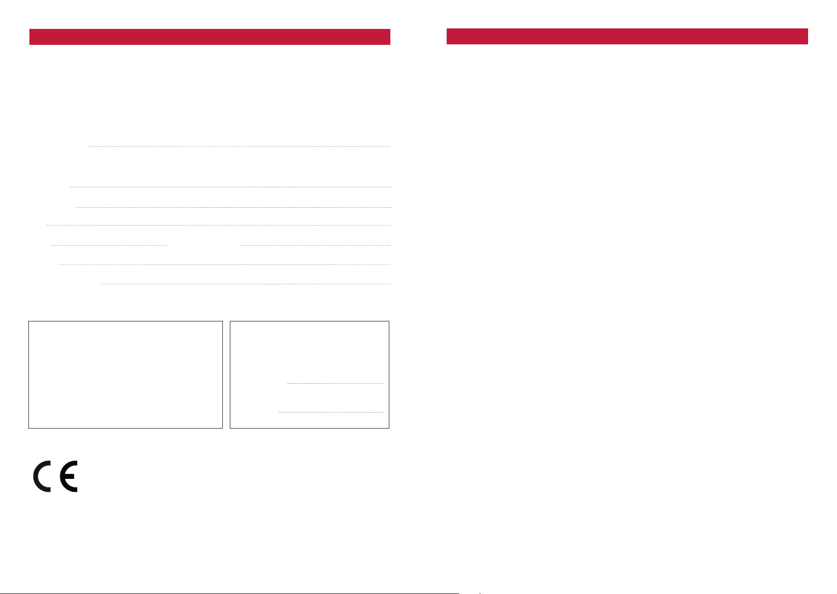
WARRANTY SLIP / GARANTIE-KARTE
MODEL: ❏ EA-MT1 ❏ EA-MT4
Date of purchase:
Your name:
Your address:
City:
State: ZIP or Postal Code:
Country:
Your phone number:
NOTES / NOTIZEN
Dealer’s address & stamp
❏ Installed by
authorized dealer
Installation date:
Inspected and
approved by:
EMPHASER
Exclusive distributor for Europe
ACR, Brändli + Vögeli AG, Bohrturmweg 1, CH-5330 Bad Zurzach, Switzerland
Phone: (+41) (0)56 269 64 64, Fax: (+41) (0)56 269 64 65, mail@acr.eu, www.acr.eu
EU Legal Representative:
ACR S & V GmbH, Industriestraße 35, D-79787 Lauchringen, Germany
24 25
Installation Approval
❏ Self-installed
by customer
Page 14

Rev. A
 Loading...