

Page 1
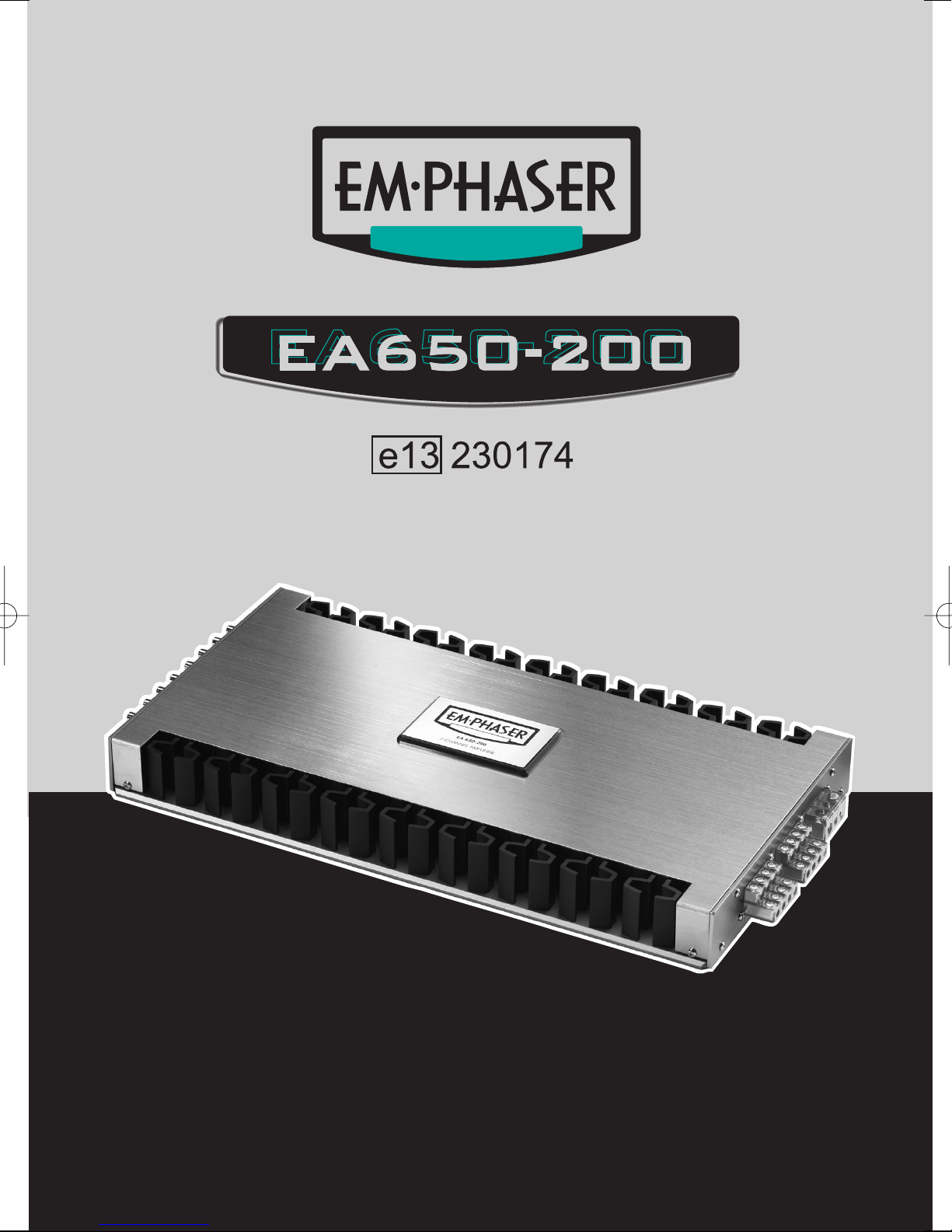
INSTALLATION & OPERATING MANUAL
EINBAU- & BEDIENUNGSANLEITUNG
7-CHANNEL POWER AMPLIFIER
Page 2

2
CONTENTS
1. DESIGN FEATURES 5
2. CONNECTIONS & CONTROLS 6-7
2.1 FRONT PANEL CONNECTION & CONTROLS 6-7
2.2 REAR PANEL CONNECTIONS 6-7
2.3 SPEAKER IMPEDANCES & WIRE INFO 7
3. AMPLIFIER MOUNTING 8
4. WIRE ROUTING 8
4.1 MAIN POWER WIRES 8
4.2 RCA & REMOTE WIRES 9
4.3 LOUDSPEAKER WIRES 9
5. INPUT LEVEL ADJUSTMENT 9
6. TECHNICAL SPECIFICATIONS 18
7. EMPHASER LIMITED WARRANTY 19
7.1 WARRANTY LIMITATIONS 19
8. WARRANTY CARD 20
Page 3

3
INHALT
1. TECHNISCHER AUFBAU / MERKMALE 11
2. ANSCHLÜSSE & BEDIENUNGSELEMENTE 12-14
2.1. EINGÄNGE & FUNKTIONEN AM FRONT PANEL 12-14
2.2 EINGÄNGE AM REAR PANEL 12-14
2.3 LAUTSPRECHER-IMPEDANZ & KABELINFO 14
3. MONTAGE DES VERSTÄRKERS 15
4. VERKABELUNG / ELEKTRISCHER ANSCHLUSS 16
4.1 HAUPT-STROMKABEL 16
4.2 CINCH- & REMOTE KABEL 16
4.3 LAUTSPRECHERKABEL 16
5. ANPASSUNG DER EINGANGSEMPFINDLICHKEIT 17
6. TECHNISCHE SPEZIFIKATIONEN 18
7. EMPHASER GARANTIE-BESTIMMUNGEN 19
7.1 GARANTIE-EINSCHRÄNKUNGEN 19
8. GARANTIEKARTE 20
Page 4

4
Congratulations!
And thank you for choosing this EMPHASER car audio amplifier!
To maximize the performance of this amplifier and your car audio system install, we recommend that
you acquaint yourself thoroughly with all capabilities and features of this EMPHASER amplifier unit.
Please read this manual carefully, before attempting the installation of this amplifier. Please retain this
manual and your purchasing / installation receipts for future reference.
IMPORTANT NOTICE:
In case you are installing your EMPHASER amplifier yourself, you should have
your installation checked and approved by an authorized professional EMPHASER dealer/installer, in order to qualify for full warranty protection and also,
to reach maximum power- and audio performance possible with your individual car audio system.
Page 5

5
1. DESIGN FEATURES
■ 7-CHANNEL CAR AUDIO AMPLIFIER: This EMPHASER amplifier allows the amplification of
7-channel speaker system
■ FULL-MOSFET CIRCUITRY: This EMPHASER amplifier line features a full MOS-FET circuitry lay-
out, implementing MOS-FET’s for power supply and output stages, to guarantee excellent sonic per-
formance and very high power output.
■ 2 OHM LOAD STABILITY: This EMPHASER amplifier works stable and reliable into 2 ohms
impedance loads. Due to the high damping factor, full control over the connected speaker system(s) is
guaranteed
■ UNCOMPROMISING DESIGN AND CONSTRUCTION: Only best electrical and electronic
components have been used for the assembly of this amplifier line. Such as double-sided glass-fiber
epoxy circuit boards equipped with high current TR output devices. The power input side features molded direct power input terminals for full unrestricted current flow
■ ADVANCED PROTECTION CIRCUITRY: The protection circuitry safe-guards the amplifier from
short-circuits at the speaker outputs, DC offset voltage at the outputs and overheating of power elec-
tronics
■ STATUS AND PROTECTION LED’S: A green and a red LED located at the side panel enable
you to monitor the operating status of your EMPHASER amp
■ ADJUSTABLE INPUT SENSITIVITY: Each RCA line-input pair accepts input voltages from
300mV to 7V, providing a good match to the line-output levels of almost any head-unit on the market
Page 6
7V 0.3V 7V 0.3V 7V 0.3V 7V 0.3V
POWER
PROTECT
GAIN GAIN GAIN GAIN
1CH 2CH 3CH 4CH 7CH5CH 6CH
1/2CH 3/4CH 5/6CH 7CH
FRONT PANEL
EA650-200
6
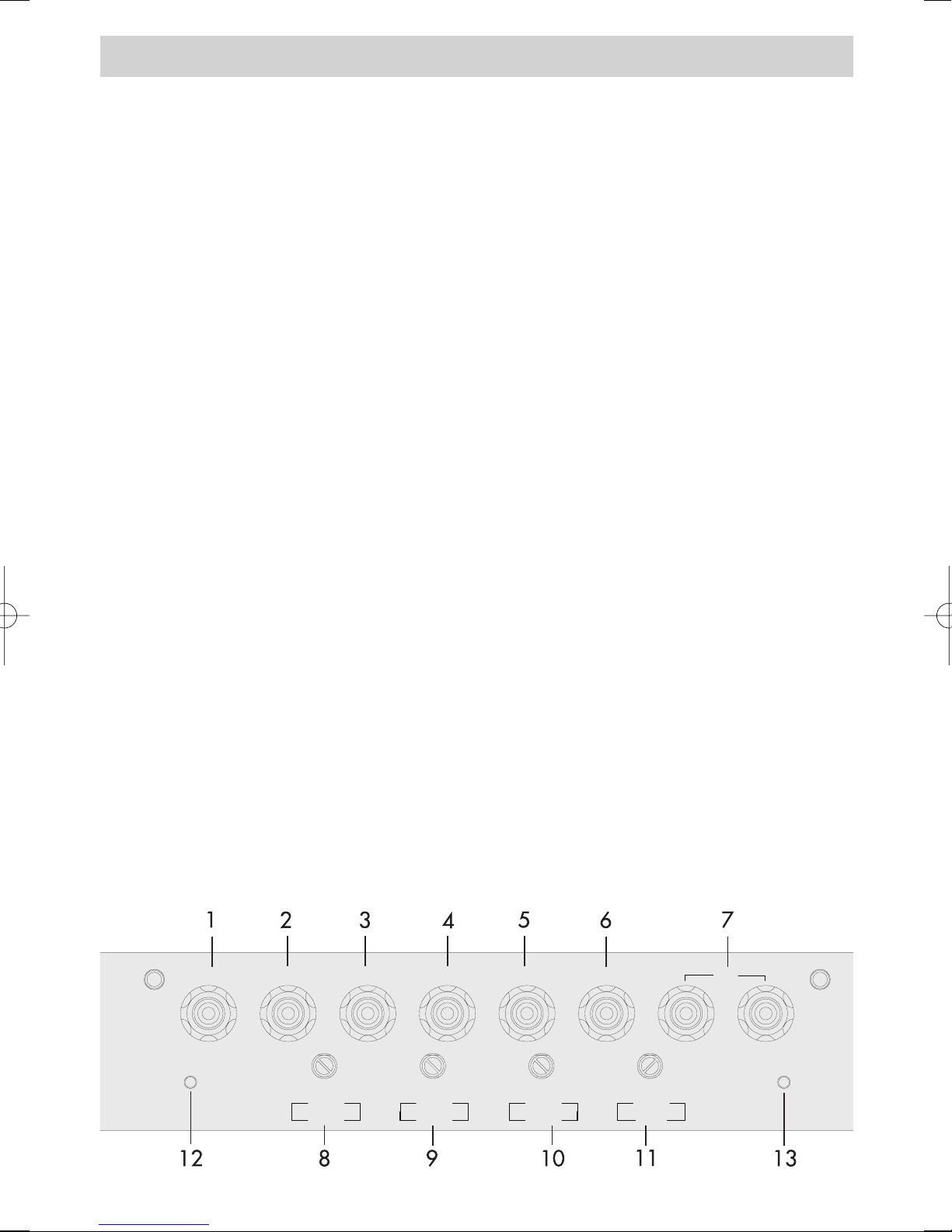
2.1 FRONT PANEL CONNECTIONS & CONTROLS
EA650-200 7-CHANNEL-AMPLIFIER
1 RCA INPUT 1-CH Low-level stereo RCA signal input for connection with head-unit.
2 RCA INPUT 2-CH Low-level stereo RCA signal input for connection with head-unit.
3 RCA INPUT 3-CH Low-level stereo RCA signal input for connection with head-unit.
4 RCA INPUT 4-CH Low-level stereo RCA signal input for connection with head-unit.
5 RCA INPUT 5-CH Low-level stereo RCA signal input for connection with head-unit.
6 RCA INPUT 6-CH Low-level stereo RCA signal input for connection with head-unit.
7 STEREO RCA INPUTS 7-CH Low-level stereo RCA signal input for connection with head-unit.
8 INPUT GAIN CONTROL 1/2-CH
Input level control for 1/2-CH amplifier section - allowing to match the output voltage of the
head-unit's RCA line-outs to the amplifier input section.
9 INPUT GAIN CONTROL 3/4-CH
Input level control for 3/4-CH amplifier section - allowing to match the output voltage of the
head-unit's RCA line-outs to the amplifier input section.
10 INPUT GAIN CONTROL 5/6-CH
Input level control for 5/6-CH amplifier section - allowing to match the output voltage of the
head-unit's RCA line-outs to the amplifier input section.
11 INPUT GAIN CONTROL 7-CH
Input level control for 7-CH amplifier section - allowing to match the output voltage of the
head-unit's RCA line-outs to the amplifier input section.
12 POWER LED
Green "operation" LED, signaling correct operation of the amplifier.
13 PROTECTION LED
Red "protection" LED, signaling faulty speaker connections or general malfunction of the
amplifier.
Page 7
REAR PANEL
EA650-200
7
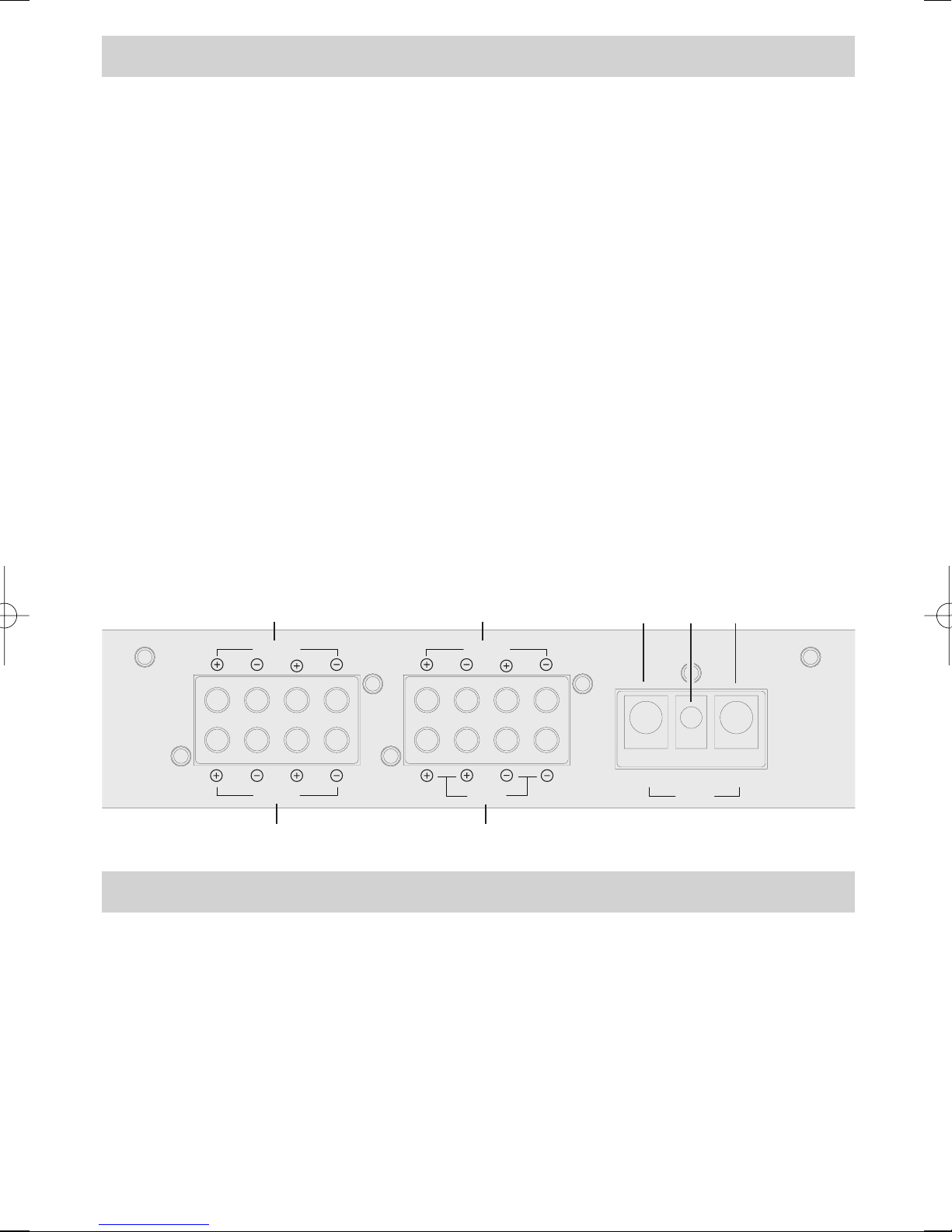
2.2 REAR PANEL CONNECTIONS
EA650-200 7-CHANNEL-AMPLIFIER
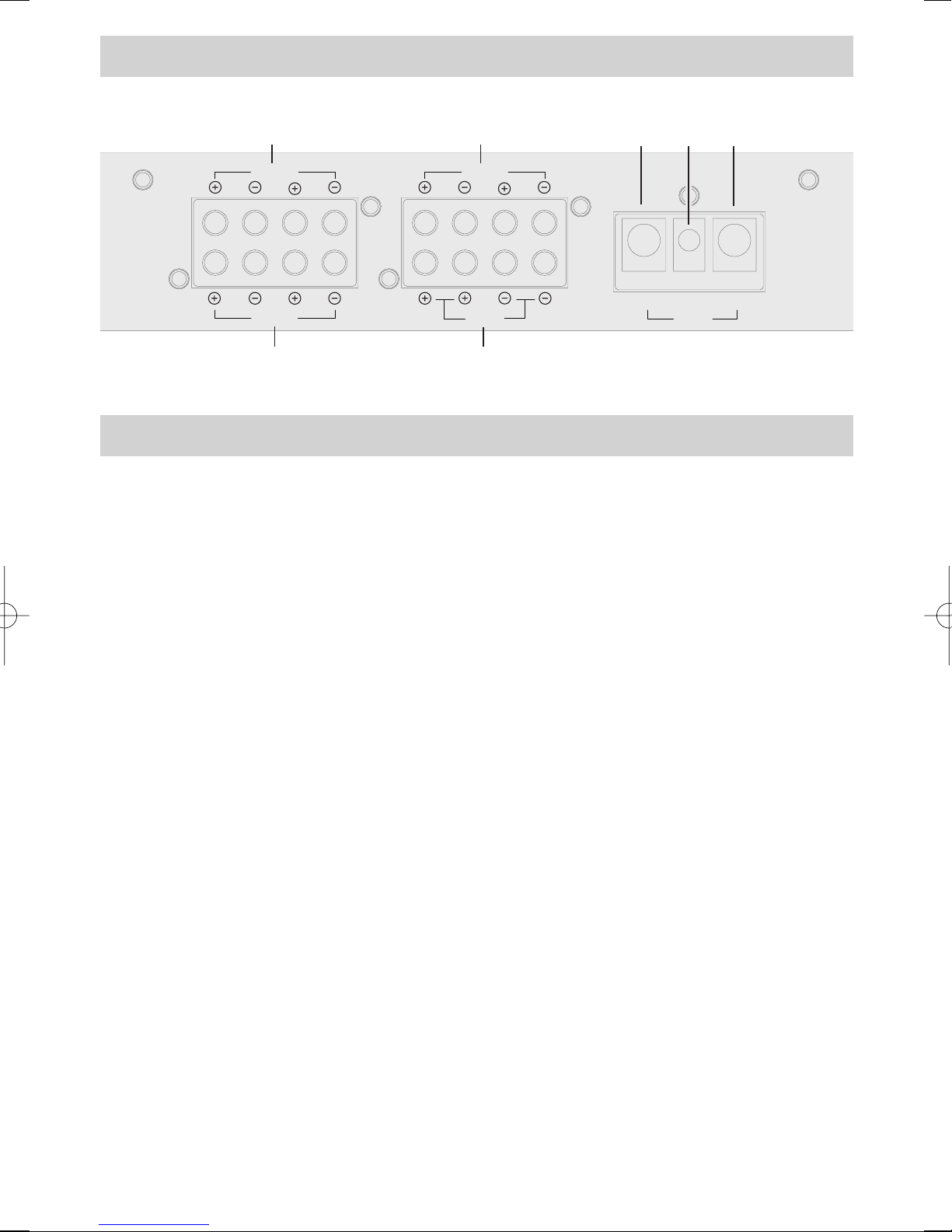
14 SPEAKER OUTPUT TERMINALS 1/2-CH
Output terminal to connect the speakers to the 1/2-CH channels of the amplifier.
15 SPEAKER OUTPUT TERMINALS 3/4-CH
Output terminal to connect the speakers to the 3/4-CH channels of the amplifier.
16 SPEAKER OUTPUT TERMINALS 5/6-CH
Output terminal to connect the speakers to the 5/6-CH channels of the amplifier.
17 SPEAKER OUTPUT TERMINALS 7-CH
Output terminal to connect the speakers to the 7-CH mono channel of the amplifier.
18 POWER INPUT TERMINAL "GND"
Terminal to connect the amplifier to the negative or ground pole of the car battery.
19 REMOTE INPUT TERMINAL "REM"
Terminal to connect the amplifier to the automatic (remote) turn-on / turn-off lead of the
head unit.
20 POWER INPUT TERMINAL "+ 12 V"
Terminal to connect the amplifier to the positive +12V pole of the car battery.
REM +12V
GND
POWER
BRIDGED
3CH 4CH
BRIDGED
1CH 2CH
BRIDGED
5CH 6CH
7CH
MONO
14
15
18 19 20
17
16
2.3 SPEAKER IMPEDANCES & WIRE INFO
The heat dissipation capacity of this amplifier has been designed to cope with low impedance loads,
note the minimum speaker impedances as stated below:
EA650-200
➡ subwoofer channel 2 ohms / satellite channels 2 ohms stereo or 4 ohms bridged
Note: EMPHASER laboratory recommends a minimum main power cable crosssection (5m total length) of 20 to 25 mm
2
, for both the positive and the ground
wires.
These recommendations guarantee trouble-free operation of your amplifier, giving you full power output.
Page 8

8
3. AMPLIFIER MOUNTING
Attention! For your own safety, disconnect the positive battery terminal (+12V) or
remove the main fuse in the positive power cable near the car battery, before you
start any wiring work!
Before you proceed to install this EMPHASER amplifier, it is recommended to map out the complete
audio system and the respective wiring required. Consider all additional electrical requirements and
accessories, such as power cables, interconnect cables etc., to complete this install. Please note that because of possible interference problems with the existing car electrics and electronics - especially the
routing of the signal cables and the chassis ground connection will have a profound impact on a trouble-free (noise free!) operation of the amplifier.
The mounting location should be carefully selected and in the interest of passive driver and passenger
safety, the amplifier must be securely mounted. Make sure that there is no wiring harness, fuel tank etc.
behind or below the mounting surface, that may be damaged by the drilling of the holes for the amplifier mounting screws. After installation, there should be a clearance of at least 5cm on all sides including the top of the amplifier heatsink. Make sure the unit is not exposed to direct sunlight, humidity,
water, oil or spill of other fluids that may enter the amplifier.
Once the location where the amplifier will be mounted is defined, use the unit as a template for the
marking of the mounting holes with pencil or felt-tip marker. The mounting holes should be pilot-drilled, using a 2,5mm or 3mm drill bit. For the actual mounting, always use the supplied rubber washers
before attaching the amp to the panel with the supplied mounting screws.
Important! There must not be a direct contact of the amplifier heatsink, bottom
panel or any other metal part of the amplifier to the vehicle! Electrical groundloops can result in audible hum!
4. WIRE ROUTING
4.1 MAIN POWER WIRES
Run the positive main power cable („+12 V“) directly from the positive terminal of the car battery to
the amplifier. For protection of your car audio system against electrical fire hazards, resulting from a
short-circuit of the main power cable to chassis ground
a main fuse holder must be inserted
within the first 30 cm of the positive main power cable.
The applicable fuse value must
be matched to the limitations of your main power cable AND the current draw of the amplifier – therefore choose an appropriate fuse value.
Attach the ground cable to the amplifier. In most cases it will be best to keep the ground cable
(„-12V“) as short as possible, i.e. to find a chassis contact very close to the amplifier. The ground power
wire must have the same cross-section as the positive power cable. The contact point where the ground
wire is attached to, must be solid and clean, i.e. free from rust or paint!
Tighten both power input terminals of the amplifier, and double check for perfect fit of both main cable
leads!
Page 9

9
4.2 RCA & REMOTE WIRES
Carefully run the audio signal interconnects and the remote wire and from the head-unit to the amplifier. As mentioned before, the audio signal cables should always be routed completely separate from
the power cables. Connect the remote (turn on/turn off) lead to the respective input terminal of the
amplifier and to the remote output of your head-unit. Now you can connect the RCA interconnects to
the respective outputs of your head-unit and to the inputs of the amplifier. Pay attention to connect the
stereo interconnects correspondingly,
left is 1CH, right is always 2CH a.s.o.
4.3 LOUDSPEAKER WIRES
Once the speaker cables have been routed, turn loose the screws of the speaker terminal binding posts
and – after inserting the stripped speaker cables – re-tighten the screws. When baring wires for connection, remove approximately 6-8mm of the insulation and after axially twisting the wires, insert the
bare ends into the corresponding speaker terminal output on the amplifier. Maintain
correct pola-
rity („“ to „“; „“ to „“).
5. INPUT LEVEL ADJUSTMENT
To reach a maximum in dynamic response from each individual head-unit/amplifier/speaker combination, it is important to set the respective input level controls („GAIN“) of all channel pairs correctly.
Before you start, you MUST set all tone controls (Bass, Mid, Treble, Loudness etc.) and the fader
on the head unit to their neutral or center positions.
Now turn all input gain controls of the installed amplifiers anti-clockwise to their minimum positions
and start with the channel pair, that drives the subwoofer system.
➡ SUBWOOFER CHANNEL
Set the volume control of your head-unit to approximately 3/4 of full volume, while playing a dynamic piece of music. Slowly increase the input gain control of the channel pair, that drives the subwoofer(s), by turning the GAIN control clockwise until you can just about hear distorted sounds coming
out of your subwoofer system. Reduce the main volume level on your head-unit to a medium listening
level.
➡ SATELLITE CHANNELS
Slowly increase the input gain control of the channel pair, that drives the loudspeaker system installed
in the front doors, by turning the GAIN potentiometer of the 1/2-CH section clockwise, until you reach
a good tonal balance with a slight emphasis of the bass range. Aim at a full bodied bass response.
Now slowly turn up the input GAIN control potentiometers of all the remaining channel pairs - until
you reach a good tonal balance of all speakers installed in your vehicle.
Page 10

10
Herzlichen Glückwunsch!
Wir danken Ihnen, dass Sie sich zum Kauf dieses EMPHASER Verstärkers entschieden haben.
Damit Sie die Wiedergabequalität und die Leistungsfähigkeit Ihres Verstärkers voll ausschöpfen können, möchten wir Sie bitten, sich eingehend mit den Möglichkeiten und technischen Features dieses
Verstärkers vertraut zu machen. Lesen Sie deshalb die nachfolgenden Abschnitte sorgfältig durch und
bewahren Sie diese Bedienungsanleitung für allfällige, vielleicht später auftauchende Fragen auf.
WICHTIGE INFO:
Wenn Sie den Einbau dieses Car-HiFi Verstärkers selbst vornehmen, lassen Sie
Ihren Einbau abschliessend von Ihrem Händler auf fachgerechte Installation
überprüfen. Damit sichern Sie sich die volle Garantieleistung und stellen weiterhin sicher, dass Ihre Car-HiFi Anlage ihre volle Klangqualität und
Leistungsfähigkeit erreicht.
Page 11

11
1. TECHNISCHER AUFBAU / MERKMALE
■ CAR AUDIO VERSTÄRKER: Dieser Verstärker dient zur Realisierung eines einbaufreundlichen
klangstarken und sehr leistungsfähigen Car Audio Systems mit sieben Kanälen
■ FULL MOS-FET SCHALTUNG: Eine FULL-MOSFET Schaltung sorgt für hohe Musikalität und sehr
hohe Ausgangsleitung
■ 2 OHM STABILITÄT: Die Kanäle dieser Verstärker Serie sind jeder für sich mit Lastimpedanzen
von bis hinunter auf 2 Ohm belastbar. Das Layout der Ausgangstufen ist ausserdem auf niedrigen
Innenwiderstand getrimmt, der Verstärker hat durch den resultierenden hohen Dämpfungsfaktor die
angeschlossenen Lautsprecher voll „im Griff“
■ KOMPROMISSLOSER AUBAU UND KONSTRUKTION: Durch die ausschliessliche
Verwendung von hochwertigsten Materialien in der Fertigung, ist die Betriebssicherheit besonders
hoch. Zum Einsatz kommen z.B. doppelseitig kaschierte Epoxy Glasfaser-Epoxydharzplatinen, hochstromfähige Transistoren etc. Weiterhin verfügt dieser Verstärker über „Direct Power-Input Terminals“,
die für vollen unlimitierten Stromfluss sorgen
■ INTELLIGENTE SCHUTZSCHALTUNG: Die integrierte Schutzschaltung erkennt Kurzschlüsse an
den Lautsprecherausgängen, Gleichspannung im Ausgangssignal und überhöhte Betriebstemperatur.
Fehlerhafte Betriebszustände führen zum sofortigen Abschalten des Gerätes
■ POWER / PROTECT LED’S: Am Side Panel auf der Cinch-Eingangsseite befinden sich zwei
LED’s, welche den Betriebs-Status des Verstärkers anzeigen
■ GROSSER REGELBEREICH DER EINGANGSEMPFINDLICHKEIT: Die Line Level
Eingangspaare akzeptieren Vorverstärker-Signale von 300mV bis 7V. Dies garantiert, dass diese
Endstufe mit allen am Markt erhältlichen Steuergeräten kombiniert werden kann
Page 12

12
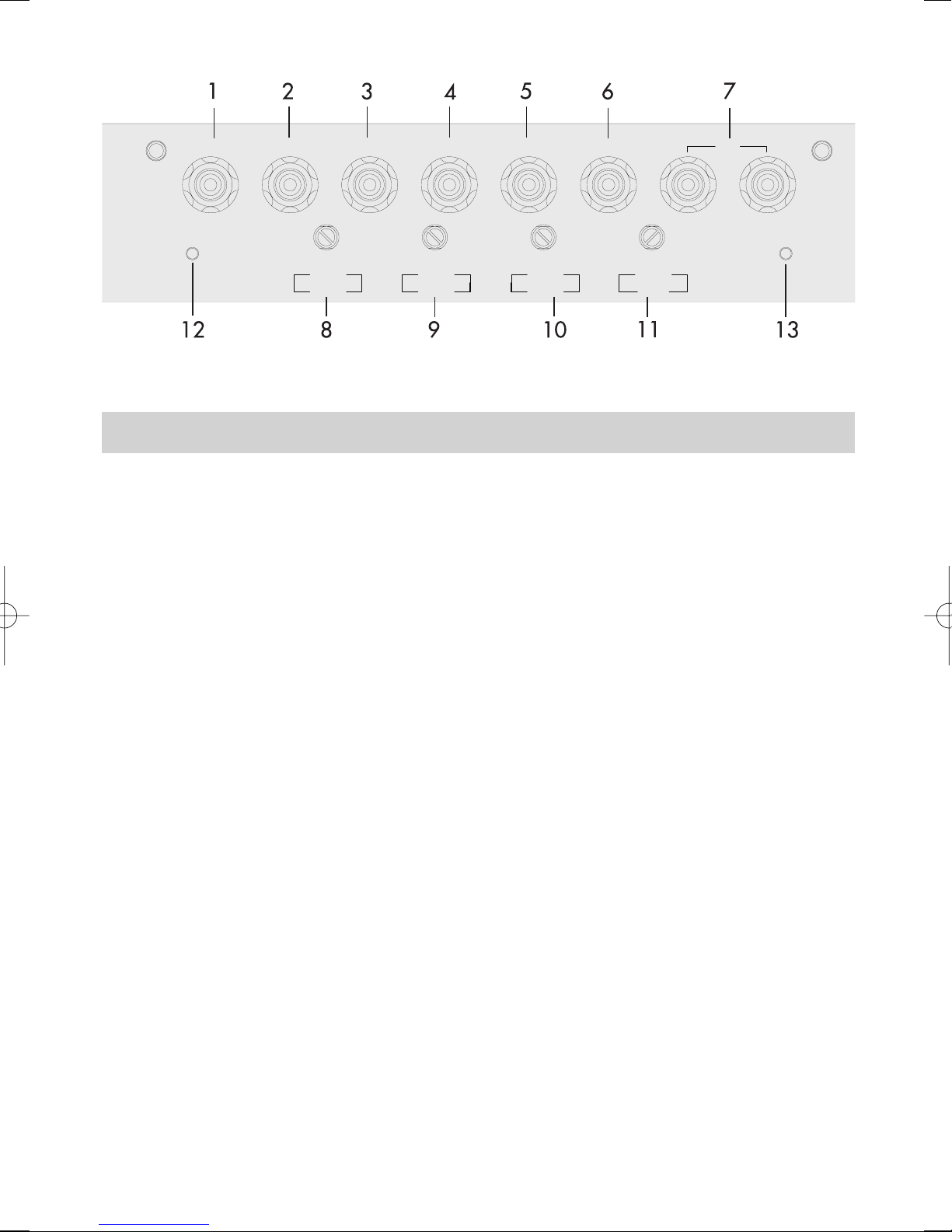
2.1. EINGÄNGE & FUNKTIONEN AM FRONT PANEL
EA650-200 7-KANAL VERSTÄRKER
1 CINCH EINGANG 1-CH
Cinch Eingangsbuchse 1-CH für den Anschluss an die Cinch Ausgänge des Steuergerätes.
2 CINCH EINGANG 2-CH
Cinch Eingangsbuchse 2-CH für den Anschluss an die Cinch Ausgänge des Steuergerätes.
3 CINCH EINGANG 3-CH
Cinch Eingangsbuchse 3-CH für den Anschluss an die Cinch Ausgänge des Steuergerätes.
4 CINCH EINGANG 4-CH
Cinch Eingangsbuchsen 4-CH für den Anschluss an die Cinch Ausgänge des Steuergerätes.
5 CINCH EINGANG 5-CH
Cinch Eingangsbuchse 5-CH für den Anschluss an die Cinch Ausgänge des Steuergerätes.
6 CINCH EINGANG 6-CH
Cinch Eingangsbuchse 6-CH für den Anschluss an die Cinch Ausgänge des Steuergerätes.
7 STEREO CINCH EINGANG 7-CH
Cinch Eingangsbuchsen 7-CH für den Anschluss an die Cinch Ausgänge des Steuergerätes.
8 REGLER EINGANGSEMPFINDLICHKEIT 1/2-CH
Eingangsempfindlichkeitsregler der Kanäle 1/2-CH, zur Anpassung an die
Ausgangsspannung des Steuergerätes.
9 REGLER EINGANGSEMPFINDLICHKEIT 3/4-CH
Eingangsempfindlichkeitsregler der Kanäle 3/4-CH, zur Anpassung an die
Ausgangsspannung des Steuergerätes.
10 REGLER EINGANGSEMPFINDLICHKEIT 5/6-CH
Eingangsempfindlichkeitsregler der Kanäle 5/6-CH, zur Anpassung an die
Ausgangsspannung des Steuergerätes.
11 REGLER EINGANGSEMPFINDLICHKEIT 7-CH
Eingangsempfindlichkeitsregler des Kanals 7-CH, zur Anpassung an die Ausgangsspannung
des Steuergerätes.
12 POWER LED
Grüne “Power” LED; signalisiert den normalen Betriebszustand der Endstufe im eingeschalteten
Zustand.
13 PROTECTION LED
Rote “Protection” LED; signalisiert eine generelle Fehlfunktion der Endstufe, wie z.B. Kurzschluss
an den Lautsprecherausgängen, Überhitzung sowie Gleichspannung an den LautsprecherAusgängen.
Page 13
13
2.2 EINGÄNGE & FUNKTIONEN AM REAR PANEL
EA650-200 7-KANAL VERSTÄRKER
14 LAUTSPRECHER AUSGANGS-TERMINAL 1/2-CH
Lautsprecheranschlussterminal für den Anschluss der Lautsprecher an die Kanäle 1/2-CH der
Verstärkers.
15 LAUTSPRECHER AUSGANGS-TERMINAL 3/4-CH
Lautsprecheranschlussterminal für den Anschluss der Lautsprecher an die Kanäle 3/4-CH der
Verstärkers.
16 LAUTSPRECHER AUSGANGS-TERMINAL 5/6-CH
Lautsprecheranschlussterminal für den Anschluss der Lautsprecher an die Kanäle 5/6-CH der
Verstärkers.
17 LAUTSPRECHER AUSGANGS-TERMINAL 7-CH
Lautsprecheranschlussterminal für den Anschluss der Lautsprecher an den Kanal 7-CH der
Verstärkers.
18 “GND” POWER INPUT TERMINAL
Eingangsterminal für den Anschluss an die Chassis-Masse des Kfz’s, resp. den Minuspol der
Fahrzeugbatterie.
19 “REM” INPUT TERMINAL
Eingangsterminal für den Anschluss des Remote-Kabels vom Headunit.
20 „+12V” POWER INPUT TERMINAL
Eingangsterminal für den Anschluss an den Pluspol der Fahrzeugbatterie.
7V 0.3V 7V 0.3V 7V 0.3V 7V 0.3V
POWER
PROTECT
GAIN GAIN GAIN GAIN
1CH 2CH 3CH 4CH 7CH5CH 6CH
1/2CH 3/4CH 5/6CH 7CH
FRONT PANEL
EA650-200
Page 14
14
2.3 LAUTSPRECHER IMPEDANZ & KABELINFO
Die Wärmekapazität der Kühlrippen dieser Endstufe wurde bei dieser Verstärker-Serie für
niederohmige Lasten ausgelegt. Die minimale Abschlussimpedanz des betroffenen Verstärker Models
entnehmen Sie bitte den technischen Daten. Die angegebenen Impedanzen für stereo und gebrückten
Betrieb sollten nicht unterschritten werden!
EA650-200
➡ Subwoofer Kanal 2 Ohm / Satelliten-Kanäle 2 Ohm stereo oder 4 Ohm gebrückt
➡ HAUPTSTROMKABEL
EMPHASER empfiehlt einen minimalen Kabelquerschnitt (bei einer Länge von 5m) von 20 – 25 mm
2
für das +12V und das Massekabel. Falls die Endstufe an sehr niederohmigen Lasten oder im
Brückenbetrieb arbeiten muss – oder eine weitere Endstufe im Anlagenkonzept integriert ist - empfiehlt sich der Einsatz von 35 mm
2
Haupt- und Masse Stromkabeln.
Diese Empfehlungen garantieren eine problemlose Funktion dieses Verstärkers, sowie die volle
Leistungsabgabe ohne übermässige Erwärmung.
➡ CINCHKABEL
Für besten Klang und hohe Einstörfestigkeit sollten nur beste Cinchkabel verwendet werden.
Verwenden Sie dreifach abgeschirmte Kabel, oder aber sogenannte „Twisted Pair“ Typen. Beachten
Sie, dass speziell die Musiksignalführenden (Cinch-) Kabel soweit als möglich von allen potentiellen
„elektrischen Störsendern“ wie Bordcomputer, Benzinpumpe, Black Boxes, etc. verlegt werden.
➡ LAUTSPERCHER KABEL
Verwenden Sie qualitativ gutes Lautsprecherkabel mit einem minimalen Querschnitt von 2.5mm2. Bei
grösseren Längen um 5m können Kabelquerschnitte bis 4.0mm
2
durchaus Sinn machen.
REAR PANEL
EA650-200
REM +12V
GND
POWER
BRIDGED
3CH 4CH
BRIDGED
1CH 2CH
BRIDGED
5CH 6CH
7CH
MONO
14
15
18 19 20
17
16
Page 15

15
3. MONTAGE DES VERSTÄRKERS
ACHTUNG! Entfernen Sie zu Ihrer eigenen Sicherheit erst das Pluskabel vom
Pluspol der Batterie!
Bei allen nachfolgend beschriebenen Installationsschritten muss der Stromkreis des Kraftfahrzeugs
unterbrochen sein! Erst
nach Abschluss aller Installationsarbeiten wird über das Pluskabel der
Stromkreis wieder geschlossen.
Bevor Sie mit der Montage dieses Verstärkers beginnen: Berücksichtigen Sie vorab die Kabelverläufe
und den Installationsort des Car-Amps.
Der Verstärker sollte im Interesse der Sicherheit bei einem Unfall möglichst gut und solide montiert werden. Die Endstufe sollte auf keinen Fall „unzugänglich verbaut“ werden, wegen der schlechten Kühlung
und auch den abschliessend erfolgenden Einstellarbeiten an den Side-Panels.
Als Montageort eignet sich z.B. ein Platz im Kofferraum oder an einem Seitenteil, bzw jeder andere
Ort, der eine saubere Installation ermöglicht.
Vermeiden Sie Montageorte mit „unbekanntem Hintergrund“. Es könnten sich ein Benzintank, hydraulische Bremsleitungen, Kabelbäume etc. dahinter verbergen! Achten Sie auch auf einen trocken, gegen
mechanische Einwirkungen geschützten Installationsort.
Halten Sie den Verstärker an den gewünschten Ort und markieren Sie mit einem geeigneten Filzstift
die Bohrposition der Befestigungslöcher.
Mit der gebotenen Vorsicht bohren Sie nun die angezeichneten Löcher mit einem 2,5 oder 3 mm
Bohrer.
ACHTUNG: Die Endstufe darf niemals direkt auf die Fahrzeugmasse des Kfz’s geschraubt werden!
Verwenden Sie die beigelegten Gummi-Isolatoren um die Endstufe(n) von der Fahrzeugmasse isoliert
zu montieren.
Legen Sie nun den Verstärker auf die vorgebohrten Löcher und schrauben Sie ihn gut fest.
Page 16

16
4. VERKABELUNG / ELEKTRISCHER ANSCHLUSS
4.1 HAUPT-STROMKABEL
Verlegen Sie nun das Pluskabel direkt von der Batterie zum Verstärker.
Innerhalb der ersten 30 cm nach dem Pluspolklemmenabgriff muss eine Hauptsicherung angebracht
werden (Absicherung des Pluskabels gegen Kurzschluss auf Fahrzeug-Masse und dadurch resultierendem Kabelbrand!)
Verwenden Sie eine dem Stromkabelquerschnitt entsprechende Haupt-Sicherung.
Schliessen Sie nun das Minuskabel am Verstärker an und an eine Massepunkt im Fahrzeug an.
Versuchen Sie dieses Kabel so kurz wie möglich zu halten. Es sollte ausserdem den selben Querschnitt
wie das Pluskabel besitzen. Achten Sie beim Massepunkt auf eine perfekt gesäuberte blanke
Metalloberfläche im Fahrzeug (schlechte Massepunkte sind für über 90 % aller Fälle der auftretenden
Störungen verantwortlich).
4.2 CINCH- & REMOTE KABEL
Verlegen Sie das oder die Cinchkabel und das Remote Kabel von der Endstufe zum Headunit..
Diese Kabel sollten unbedingt räumlich getrennt von der Stromzuführung des Verstärkers eingezogen
werden. Schliessen Sie das Remote-Kabel an das mit „REM“ bezeichnete Terminal an der Endstufe und
an das mit Antenna-Rem. oder Amplifier-Rem. bezeichnete Kabel Ihres Steuergerätes an.
Anschliessend stecken Sie die Cinchkabel in die Cincheingangsbuchsen des Verstärker ein. Beachten
Sie hierbei die Seitenkennung, d.h. 1-CH ist links, 2-CH ist rechts, usw!
4.3 LAUTSPRECHERKABEL
Schliessen Sie nun die Lautsprecher Kabel an. Entfernen Sie ca. 6-8 mm der Isolierung des LS-Kabels
und beachten Sie die richtige Polung der Lautsprecherkabel am Terminal (Plus auf
Plus, Minus auf Minus).
Ziehen Sie die LS-Schraublemmen satt an.
Schliessen Sie nun den Stromkreis zum Verstärker durch das Einsetzen der Hauptsicherung. Ihr
Verstärker sollte nun beim Einschalten des Steuergerätes durch das Aufleuchten der grünen Power-LED
die Betriebsbereitschaft anzeigen. Leuchtet die Protection-LED rot auf, ist Ihre Installation fehlerhaft.
Gehen Sie die gesamten Installationsanweisungen nochmals genau durch.
Page 17

17
5. ANPASSUNG DER EINGANGSEMPFINDLICHKEIT
Die korrekte Eingangsempfindlichkeitseinstellung ist wichtig für die Ausnutzung des optimalen
Dynamikspielraumes Ihrer Steuergerät / Verstärker / Lautsprecherkombination. Diese
Empfindlichkeitseinstellung beeinflusst das Grundrauschen ebenso wie die verzerrungsfrei erzielbare
Maximallautstärke.
ACHTUNG! Bevor Sie mit der Anpassung der Eingangsempfindlichkeiten anfangen müssen zuallererst
alle Klangregler, sowie auch der Fader/Balance in die Mittel (Neutral) Position gebracht werden. Die
Loudnessfunktion ist auch zu deaktivieren.
SUBWOOFER KANAL
Drehen Sie den oder die Input GAIN Regler an der (oder den Endstufen) im Gegenuhrzeigersinn auf
die Minimumposition. Zuerst wird immer der Pegelabgleich des Kanalpaares am Verstärker vorgenommen, welches das Subwoofersystem treibt!
Stellen Sie den Lautstärkeregler Ihres Steuergerätes auf ca. 3/4 der Maximallautstärke und benutzen
Sie für die nun kommende Einstellung ein gut aufgenommenes dynamikreiches Musikstück.
Drehen Sie nun den GAIN Regler vom Subwoofer Kanalpaar langsam im Uhrzeigersinn auf, bis Sie
gerade die Verzerrungsgrenze im Bassbereich erreichen. Dann drehen Sie den GAIN Regler gerade
soweit zurück, dass die Verzerrungen wieder verschwinden.
FRONT KANÄLE & REAR KANÄLE
Stellen Sie nun die Lautstärke an Ihrem Steuergerät auf einen mittleren Lautstärke Wert, und drehen
Sie den GAIN Regler vom Kanalpaar der Frontsysteme (z.B. 1/2-CH für die Satelliten in den
Vordertüren, oder den Center Speaker) langsam auf. „Dosieren“ Sie die Lautstärke des oder der vorderen Lautsprechersystems so hinzu, dass sich ein ausgewogener aber immer noch basskräftiger
Klang ergibt. Nun werden alle weiteren Kanälen entsprechend hinzudosiert, z.B. das
Lautsprechersystem im Heck, etc.
Page 18

18
5. TECHNICAL SPECIFICATIONS
EA650-200
7-CHANNEL FULL RANGE DIGITAL AMPLIFIER
50Wrms x 6 & 200Wrms x 1 @ 4 ohms (> 0.1% THD / 13.8V)
75Wrms x 6 & 320Wrms x 1 @ 2 ohms (> 0.3% THD / 13.8V)
150Wrms x 3 & 200Wrms x 1 mono bridged @ 4 ohms (> 0.3% THD / 13.8V)
2 ohms stable stereo mode / 4 ohms stable bridged mode
Full-MOSFET amplification circuitry
Variable input sensitivity: 0.3 – 7V
Damping factor @ 4 ohms: < 350
Signal to noise ratio: < 100dB
Channel separation: < 50dB
25mm2direct power input terminals
Dimensions WxHxD: 505 x 50 x 275mm
Net weight: 6.86kg
Page 19

19
6. EMPHASER LIMITED WARRANTY
Dear customer
Please read the warranty specifications below carefully.
Should your EMPHASER product require warranty service, please return it to the retailer from whom
it was purchased or the distributor in your country. Please do not send any product to EMPHASER
Inc. U.S.A. Should you have difficulty in finding an authorized EMPHASER service center, details are
available from your local distributor.
This EMPHASER amplifier is fully warranted against defective materials or workmanship for a period
of
two years from date of purchase at retail. Warranty work will not be carried out unless this
warranty certificate is presented fully completed with serial number, purchaser’s address, purchasing
date and dealer stamp together with the original sales slip and either an authorized dealer’s confirmation of installation or authorized dealer’s installation approval!
6.1 WARRANTY LIMITATIONS
This warranty does not cover any damage due to:
1. Unauthorized or unapproved installation, incorrect audio or mains connection(s).
2. Exposure to excessive humidity, fluids, sun rays or excessive dirt or dust.
3. Accidents or abuse, unauthorized repair attempts and
modifications not explicitly authorized by the manufacturer.
This warranty is limited to the repair or the replacement of the defective product at the manufacturer’s option and does not include any other form of damage, whether incidental, consequential or
otherwise. The warranty does not cover any transport costs or damages caused by transport or shipment of the product.
6. EMPHASER GARANTIE-BESTIMMUNGEN
Sehr geehrter Kunde, sehr geehrte Kundin
Wir bitten Sie, die Originalverpackung für einen allfälligen Transport aufzuheben und die untenstehenden Garantie-Bestimmungen genau durchzulesen.
Sollten Sie für Ihren Verstärker Garantie-Leistungen beanspruchen, wenden Sie sich bitte direkt an
den Händler, bei dem Sie das Gerät gekauft haben. Bitte senden Sie keine Geräte an EMPHASER
Inc. U.S.A. Bei Schwierigkeiten, ein geeignetes EMPHASER Service-Center zu finden, erhalten Sie
bei Ihrem jeweiligen Landes-Vertrieb weitere Informationen.
Der Hersteller gewährleistet auf diesen EMPHASER Verstärker für den Fall von Material- oder
Herstellungsfehlern
zwei Jahre Garantie, ab Kaufdatum in Fachhandel. Garantie-Ansprüche kön-
nen nur mit einer korrekt und vollständig ausgefüllten Garantie-Karte zusammen mit dem OriginalKaufbeleg geltend gemacht werden
.
6.1 GARANTIE-EINSCHRÄNKUNGEN
Nicht unter Garantie fallen Schäden infolge von:
1. nicht-autorisierter bzw. nicht vom autorisierten Händler/Installateur geprüftem Selbst-Einbau oder
inkorrekten Audio- oder Stromanschlüssen.
2. schädlichen Einwirkungen von übermässiger Feuchtigkeit, Flüssigkeiten, Hitze,
Sonneneinstrahlung oder übermässiger Verschmutzung.
3. mechanischer Beschädigung durch Unfall, Fall oder Stoss; Schäden durch nicht autorisierte
Reparaturversuche oder nicht durch den Hersteller ausdrücklich autorisierte Modifikationen.
Die Garantie dieses Produkts bleibt in jedem Fall auf die Reparatur bzw. den Ersatz (Entscheidung
beim Hersteller) des jeweiligen EMPHASER Produkts beschränkt. Schäden durch unsachgemässe
Verpackung und daraus resultierende Transportschäden werden nicht durch diese Garantie gedeckt.
Jeder über diese Garantie-Erklärung hinausgehende Anspruch und jede Haftung für direkte oder
indirekte Folgeschäden werden ausdrücklich abgelehnt.
Page 20
7. WARRANTY CARD / GARANTIEKARTE
Model name:
POWER AMPLIFIER EA 650-200
Serial Number:
Date of purchase:
Your name:
Your address:
City:
State: ZIP or Postal Code:
Country:
Your phone number:
Limited Warranty: 24 Months
(Valid with authorized Installation Approval only)
Dealer’s address & stamp
❏ Installed by
authorized dealer
Installation date:
Inspected and
approved by:
Installation Approval
❏ Self-installed
by customer
EMPHASER Inc.,
Wyoming, Michigan, U.S.A.
 Loading...