

Page 1
1
2- AND 4-CHANNEL POWER AMPLIFIER
INSTALLATION & OPERATING MANUAL / EINBAU- & BEDIENUNGSANLEITUNG
EA2190490 Manual neu 31.07.2000 19:02 Uhr Seite 1
Page 2

2
Design Features . . . . . . . . . . . . . . . . . . . . . . . . . 4
Connections & Controls . . . . . . . . . . . . . . . . . . . 5
Installation Planning . . . . . . . . . . . . . . . . . . . . . 7
Amplification Modes . . . . . . . . . . . . . . . . . . . . . 8
System Configuration EA2190 . . . . . . . . . . . . . . 9
System Configuration EA490 . . . . . . . . . . . . . . 10
Settings . . . . . . . . . . . . . . . . . . . . . . . . . . . . . . . 12
Specifications . . . . . . . . . . . . . . . . . . . . . . . . . . 14
Warranty Policy . . . . . . . . . . . . . . . . . . . . . . . . 27
Warranty Certificate . . . . . . . . . . . . . . . . . . . . 28
Technischer Aufbau / Merkmale . . . . . . . . . . . 16
Bedienungselemente . . . . . . . . . . . . . . . . . . . .17
Installation . . . . . . . . . . . . . . . . . . . . . . . . . . . . 19
Konfigurationsvorschlag EA2190 . . . . . . . . . . 21
Konfigurationsvorschlag EA490 . . . . . . . . . . . 22
Einstellungen . . . . . . . . . . . . . . . . . . . . . . . . . . 24
Technische Daten . . . . . . . . . . . . . . . . . . . . . . . 26
Garantiebestimmungen . . . . . . . . . . . . . . . . . . 27
Garantie-Karte . . . . . . . . . . . . . . . . . . . . . . . . . 28
Contents/Inhalt
EA2190490 Manual neu 31.07.2000 19:02 Uhr Seite 2
Page 3
3
Congratulations
And thank you for choosing an EMPHASER automotive amplifier! You now
own a product of uncompromising engineering philosophy and meticulous
craftmanship, designed and thoroughly tested by the laboratories of
EMPHASER Inc., Wyoming U.S.A.
The EMPHASER amplifier series is setting new standards in power handling, sound quality and user-friendly control features.
To maximize the performance of your automotive audio system, we recommend that acquaint yourself thoroughly with its full capabilities and features. Please read this manual carefully before undertaking the installation of
this amplifier.
EMPHASER amplifiers are the result of outstanding craftmanship and the
highest quality control standards. When properly installed these amplifiers
will provide you with many years of incomparable listening pleasure.
IMPORTANT NOTICE:
In case you are installing your EMPHASER amplifier
yourself, you should have your installation checked
and approved by an authorized, professional EMPHASER
dealer/installer in order to qualify for full warranty
protection and best power handling and sound quality possible with your individual automotive audio
system.
EA2190/EA490 OWNER’S MANUAL & INSTALLATION GUIDE
EA2190490 Manual neu 31.07.2000 19:02 Uhr Seite 3
Page 4
4
■ Uncompromising Design and Construction using only the best
electrical and electronic components including glass-fibre reinforced epoxy
circuit boards, high-current handling printed circuitry and low-loss solid brass
24 K gold-plated power and signal input connecting blocks/sockets and loudspeaker terminal blocks.
■ Integrated Electronic Filtering Optionwith separate Low- and High-
Pass Filter sections with 12 dB/oct. slopes. The low- or high-pass cross-over
frequencies are continuously variable between 50 Hz and 250 Hz.
■ Advanced Protection Circuitry 'sensing' short-circuits and DC vol-
tage at the speaker outputs and overheating of power electronics. Faulty
connections or operating modes will cause the amplifier to shut-off immediately.
■ Operating Mode / Fault Monitor LED monitoring the correct func-
tion of the amp.
■ 1 Ohm Stability for simultaneous connection of several loudspeaker
systems on a 2- or 4-channel amplifier or for Tri-Mode amplification. The use
of a regulated MOSFET power supply provides high power headroom for
low-impedance loads. All amplifiers allow bridging mode for increased
power output, e.g. for subwoofer amplification.
■ Stereo, Mono-Bridged and Tri-Modepossible without amplifier in-
ternal switching.
■ Adjustable Input Sensitivity accepting input voltages from 150
mV to 3V allowing system combinations with almost every head-unit on the
market.
■ Soft Start / Soft Turn-Off Circuitry eliminating any amplifier rela-
ted turn-on/turn-off noises.
■ Easy Access Fuse(s) on the control panel.
DESIGN FEATURES
EA2190490 Manual neu 31.07.2000 19:02 Uhr Seite 4
Page 5

5
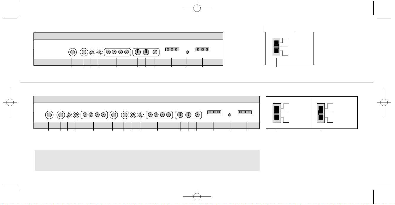
Side Panel Connections & Controls
EMPHASER EA2190/ EA490 Side Panel View
Description of Connections & Controls
1.+2. RCA Inputs (”Left“ & ”Right“). Low-level signal input for
connection with the line-outputs of the head-unit, external electronic
equalizers, cross-overs etc. (see section 2.6.1)
N.B. The 4-channel amplifier model EA490 features 2 pairs of RCA input
sockets, one for „FRONT“ one for „REAR“.
3. Highpass / Lowpass Frequency Control (”FREQ. Hz“) of the
integrated electronic filters. To be used in combination with the
respective bottom panel controls ("Electronic Filter Setting").
(see section 3.2)
4. Input Sensitivity Control (“LEVEL“) to match the RCA output
signal from the head-unit etc. to the amplifier input (see section 3.1)
5. Speaker Connecting Terminal („ L R ”) for the
connection of the loudspeakers (see 2.6.2)
Please note: The 4-channel model EA490 has two speaker output sections; one for„Front“ and one for „Rear”.
6. ”GND“ for connection to chassis ground or negative terminal of car
battery (see section 2.6.4)
7. ”+12V” for connection to positive terminal of car battery
(see section 2.6.3)
8. ”REM“ for the automatic (remote) turn-on/turn-off of the power
amplifier from the head unit's remote lead (or antenna remote
lead). (see section 2.6.1)
9. FUSE („FUSE“) for protection of the amplifier-internal electronics
against electrical overload or wrong operation/manipulation.
10. Operating Mode / Fault Monitor LED („POWER PROTECTION“)
sensing signalling operating mode and faults. (see section 2.6.5)
11 . Electronic High-/ Low-Pass Filter Selector for the optional
selection of 'High- or Low-Pass Filter Mode' in combination with the
High- or Low-Pass Frequency Control(s) („FREQ. Hz“) on the side
panel.
Please note: The electronic filtering selectors are only
accessible from the bottom panel of the amplifiers.
Therefore the operating mode must be selected before
final installation of the amplifier! The 4-channel
model EA490 features two separate filtering sections;
one for „Front“ and one for „Rear“. (see section 2.2)
CONNECTIONS & CONTROLS
EA2190490 Manual neu 31.07.2000 19:02 Uhr Seite 5
Page 6
6
4 LEVEL
5 L R
6 GND
7 +12V
8 REM
9 FUSE
10 LED POWER PROTECTION
11 HIGH-/ LOW-PASS FILTER SETTING
(see previous page)
1 LEFT
2 RIGHT
3 FREQ. Hz
1 2 3 4 5 6 7 8 9 10 9
1 2 3 4 5 1 2 3 4 5 6 7 8 9 10 9
EMPHASER EA2190
FILTER SETTINGS
LOW PASS
FLAT
HIGH PASS
LOW PASS
FLAT
HIGH PASS
LOW PASS
FLAT
HIGH PASS
11
EMPHASER EA2190
2-Channel Amplifier
Bottom Panel Controls
EMPHASER EA490
4-Channel Amplifier
Bottom Panel Controls
EMPHASER EA490
11
11
FRONT FILTER SETTINGS REAR FILTER SETTINGS
EA2190490 Manual neu 31.07.2000 19:02 Uhr Seite 6
Page 7

7
Before you attempt to conduct the installation of the amplifier, it is recommended to map out the complete audio system and the respective wiring
required. Consider all electrical requirements, i.e. safe mounting, sufficient
ventilation and availability of space to access the control panel. Please note
that – because of possible interference problems with the existing car electrics and electronics – especially the routing of the signal cables and the
chassis ground connection will have a profound influence on a troublefree operation of the installed system. It is recommended to use quality
installation material.
If you have no or only little experience with car audio installations, we
strongly recommend to consult your nearest authorized EMPHASER dealer/installer.
2.2 Selecting Operating Modes (Bottom Panel Controls)
As the operating mode selector(s) are only accessible from the bottom panels
of the amplifiers, the operating mode has to be decided and set, before
mounting the amplifier.
– Switch Position "FLAT": Fullrange Mode, ideal for driving soundboards and
high-power-handling rear systems.
– Switch Position "HPF": High-Pass Mode, cutting the low frequency parts of
the music signal below the frequency setting on the side panel ("FREQ.
Hz"). This mode is ideal for driving coaxial and separate component speaker systems.
– Switch Position "LPF": Low-Pass Mode, cutting the high frequency parts of
the music signal above the frequency setting on the side panel ("FREQ.
Hz"). This mode is ideal for driving subwoofer(s).
Please note that the 2-channel model EA2190 feature one single 3-position
mode selector, while the 4-channel model EA490 features two different
3-position mode selectors.
– Switch Modes „Front“: „LPF”, „FLAT“ or „HPF”
– Switch Modes „Rear“: „LPF”, „FLAT“ or „HPF”
Therefore the 4-channel amplifier EA490 allows driving a fully active stereo
subwoofer/satellite system consisting e.g. of a pair of coaxials or separate
component systems in the doors or dashboard operating in HPF mode (using
the two "FRONT" channels) and a subwoofer in the trunk operating in LPF
mode (using the two "REAR" channels see system configuration of the EA490).
The coaxials or component speaker system will be connected to the "FRONT"
section speaker outputs and the subwoofer(s) to the "REAR" speaker outputs.
Please note: In case your head-unit has a separate subwoofer-signal output
and you want to make use of the amplifiers integrated LPF mode, make sure
INSTALLATION PLANNING
EA2190490 Manual neu 31.07.2000 19:02 Uhr Seite 7
Page 8
8
the head-unit's low-pass frequency setting is not lower than the frequency setting ("FREQ. Hz") on your amplifier. In case your head-unit does not have a
separate subwoofer signal output, you will have to 'split' the stereo input
signal by means of a Y-adaptor cable, so that you will have two connectors
for each channel available: one for LPF (using "REAR" section of the amplifier) and one for HPF (using "FRONT" section).
2.3. Stereo, Bridged-Mono or Tri-Mode Amplification
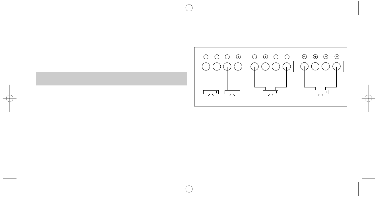
Stereo Connection: please refer to the connecting diagrams below and
make sure, that the polarity of your speaker wiring is correct all the way down
from amplifier output to the speaker terminals: to and to .
Mono-Bridged Connection: In mono (bridged) mode, please refer to the
respective connecting diagram. The mono-mode will provide approximately triple the rated output power of a single stereo channel. In mono-mode, the
load impedance must be kept at or above 2 ohms!
Amplification Modes (for any pair of stereo outputs)
Tri-Mode Connection: This amplification mode describes the connection
of a stereo speaker pair as in the regular stereo mode but with an additional,
third speaker (usually a subwoofer) connected to the same set of speaker terminals. For correct tri-mode connection, please refer to the respective diagram. For best results with tri-mode systems it is recommended to use a special passive tri-mode cross-over. The impedance of each speaker combined
in a tri-mode system should not be below 4 ohms.
AMPLIFICATION MODES
R
L
STEREO CONNECTION
R
L
BRIDGED MONO CONNECTION
R
L
BRIDGED MONO CONNECTION
EA2190490 Manual neu 31.07.2000 19:02 Uhr Seite 8
Page 9
9
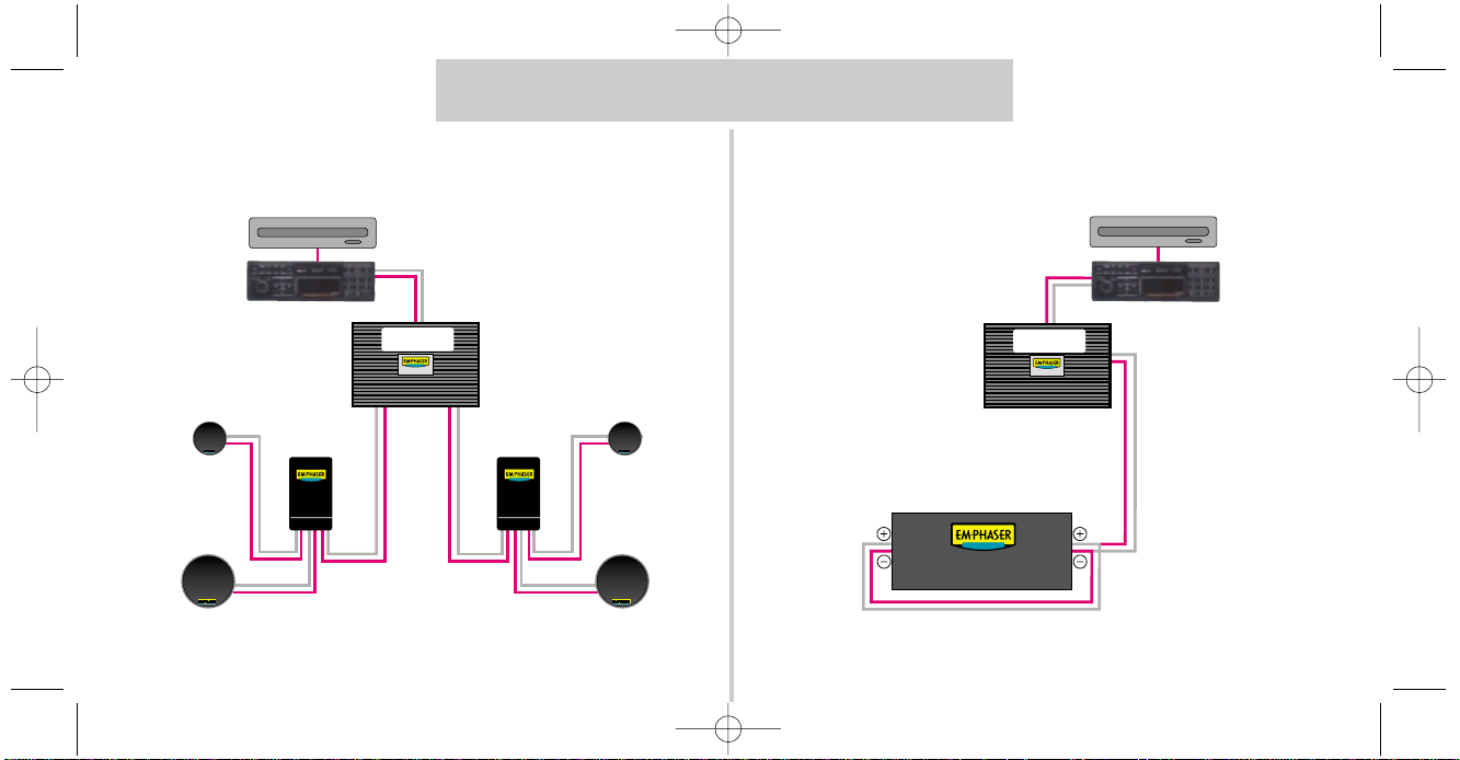
SYSTEM CONFIGURATIONS EA2190
2-Channel Mode Mono Mode
Great American Car Audio
Great American Car Audio
Great American Car Audio
Great American Car Audio
PRE-OUT „REAR”
EA2190
PRE-OUT ”FRONT”
CD-CHANGER
HEAD-UNIT
X-OVER
BASS-MIDRANGE
TWEETER
X-OVER
BASS-MIDRANGE
TWEETER
PRE-OUT „REAR”
EA2190
PRE-OUT ”FRONT”
SUBWOOFER PARALLEL (2 Ω)
CD-CHANGER
HEAD-UNIT
EA2190490 Manual neu 31.07.2000 19:02 Uhr Seite 9
Page 10
Great American Car Audio
Great American Car Audio
Great American Car Audio
Great American Car Audio
Great American Car Audio
Great American Car Audio
Great American Car Audio Great American Car Audio
BASS-MIDRANGE
CD-CHANGER
HEAD-UNIT
X-OVER
X-OVER
TWEETER
X-OVER
X-OVER
BASS-MIDRANGE
TWEETER
EA490
BASS-MIDRANGE
TWEETER
BASS-MIDRANGE
TWEETER
10
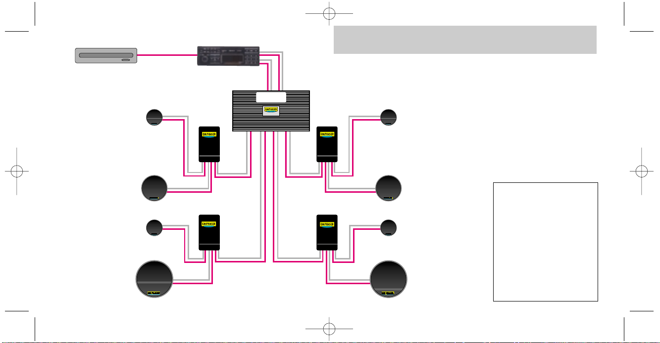
Please note:
This configuration uses the
4-channel amplifier
EA490 either in
– HPF („High-Pass”) Mode
for „FRONT” and
– ‘Fullrange’ („FLAT”) Mode
for „REAR”
or
– Fullrange („FLAT”) Mode
for „FRONT” & „REAR”
SYSTEM CONFIGURATION EA490
EA2190490 Manual neu 31.07.2000 19:02 Uhr Seite 10
Page 11

11
2.6. Wiring
IMPORTANT NOTICE! Disconnect the positive battery terminal („+12 V“) before any wiring work!
Wiring Tips!
Use rubber grommets when running cables through any metal or sharp plastic, to prevent accidental shorting or shearing. Make sure that the cables
do not interfere with normal operation of the vehicle. Especially the signal
cables (RCA interconnects) should be kept far away from any potential
sources of electrical interference e.g. electronic vehicle management systems
(engine computers, relays etc.) fuel pumps, wiring harnesses etc.
2.6.1 Carefully run the audio signal and remote switching cable(s) from the head-unit to the amplifier. The audio signal cables
should be routed completely separate from the power cables. Use only double
or triple shielded quality cables! Connect the remote (turn on/turn-off) lead
to the respective outputs of the head-unit and the amplifier. If your head unit
does not have a remote lead, you may also use the antenna remote option.
Now you connect the audio cable to the respective outputs on the head-unit
and inputs on the amplifier.
2.4 Location of the Amplifier
The location of the power amplifier should be well selected. In the interest
of passive driver and passenger safety, solid mounting of the amp unit is crucial. The actual mounting surface should be completely flat. Any mounting
position allowing for a good air stream across the cooling fins of the amplifiers heatsink will improve cooling (at low impedance loads!) and long-term
stability dramatically. Make sure there is no wiring harness, fuel tank etc. behind or below the mounting surface, that may be damaged by the drilling of
the holes for the amplifier mounting screws. After installation, there should be
a clearance of at least 5 cm on all sides including the top of the amplifier heatsink. Make sure the unit is not exposed to direct sunlight, humidity, water, oil
or other fluids that may enter the amplifier. It is also recommended that the
location of the amplifier allows easy access of all side panel controls.
2.5 Mounting the Amplifier
Once the location for the amplifier is defined, use the unit as a template for
the marking of the mounting holes with a pencil or felt-tip. The mounting
holes should be pilot-drilled using a 2,5 mm or 3 mm drill. For the actual
mounting, the supplied rubber grommets have to be pressed into the mounting holes of the amplifier, before inserting the supplied mounting screws. The
rubber grommets protect the amplifier from electrical ground-loops that can
easily result in audible hum!
EA2190490 Manual neu 31.07.2000 19:02 Uhr Seite 11
Page 12

the head-unit and carefully re-check the steps 2.6.1 to 2.6.5
The same applies, if the LED does not light-up at all.
3.1 Input Sensitivity Setting („LEVEL“)
To obtain the best sound quality and dynamics from your car-audio system,
it is essential to set the correct input sensitivity on the amplifier. This setting has
direct influence on the signal to noise ratio and the maximum distortion free
power output.
„Level“ Adjustment Tips
Turn the "LEVEL" control knob counter-clockwise to its minimum position.
Set the volume control of the head-unit to approximately 3/4 of full volume.
While playing a dynamic track, slowly increase the "LEVEL" control of the amplifier, until you reach the first signs of distorted sound. Slowly turn back the
"LEVEL" control, until the distortion disappears. This is the correct input sensitivity setting.
Considering the 4-channel model EA490 this procedure has to be carried out
twice, once for the front channels and once for the rear channels. In case you
12
2.6.2 Connect the loudspeaker wires. Use speaker cable of minimum 1,5 mm
2
- preferably 2,5 mm2cross section. When stripping wires for
connection, remove approximately 8 mm of the insulation. Insert the bare
ends into the speaker terminal output section on the amplifier. Be sure to follow correct polarity ("" to ""; "" to "" ). Tighten the allen screws of
the amplifier.
2.6.3 Run the positive power cable („+12 V“) directly from the
positive terminal of the car battery to the amplifier. To protect
your car audio system against shorting and your entire car against electrical fire hazards, you must insert a main-fuse (holder) within the first 30 cm of
the battery. Do not insert the fuse until the wiring is completed!
Now you route the ground cable to the amplifier. A very close
point of the chassis ground to the amplifier is preferable. The ground cable
should have the same cross-section as the positive ("+12V") power cable! The
contact-point on the car chassis must be solid and clean, i.e. free from rust or
paint etc. A bad ground contact not only brings an increased risk of interferences but also drastically reduces the voltage resulting in reduced power output and high distortion already at low listening levels.
2.6.5 Close the electrical circuit by inserting the main fuse.
After turning-on the head-unit, the mode/operating LED of the power amplifier should light-up green. If the LED is red, the installation is faulty! Turn off
SETTINGS
EA2190490 Manual neu 31.07.2000 19:02 Uhr Seite 12
Page 13

13
are using the EA490 as in an active subwoofer/satellite system (as e.g. described under section 2.2) you should set the both frequency controls ("FREQ.
Hz") of "FRONT and "REAR" to center position (12 o'clock). Then the start
with the adjustment of the subwoofer"LEVEL", i.e. the "REAR" system. Turn the
sensitivity "LEVEL" on the "REAR" control section of the amplifier at 3/4 to full
(clockwise). Now you mix-in the mid-high frequencies of the 'satellites' using
the "LEVEL" control of the ''FRONT" section until you reach the best balanced
sound with the current cross-over frequency settings. The following section of
this manual (3.2) will describe the fine-tuning of the cross-over frequencies,
after which a final fine-tuning of the input sensitivity setting for the 'satellites'
("FRONT" section) has to be carried out again.
3.2 Cross-Over/Filtering Adjustments („FREQ. Hz“)
All EMPHASER amplifiers incorporate an electronic crossover, that is activated through the switches on the bottom panel of the amplifiers. The individually selectable filtering modes may either be used to drive a subwoofer (in
"LPF"/Low-Pass mode) or a 'satellite' type coaxial or component system (in
"HPF"/High-Pass mode). The 4-channel model EA490 even allows both amplification modes simultaneously.
The correct setting has to be determined by ear. The two most important factors for the individual adjustment will be the reproduction of the mid-bass frequencies and the required power-handling of the satellites system. If the cross-
over frequency is set too low, the mid-bass reproduction will be increased,
but the power-handling of the 'satellites' will be decreased. If the cross-over
frequency is set too high, the mid-bass reproduction will become 'thin', while the power-handling of the 'satellites' will increase. Try to find a setting, that
will suit your personal listening preferences and the physical and electrical
capabilities of your equipment best.
If you are using your (2-channel) amplifier to drive a subwoofer, you should
ideally select your "LPF" cross-over frequency between 50 Hz and 90 Hz. Adjust the "FREQ. Hz" control in a way, that the bass reproduction is dry, yet still
offering a good and solid low end extension. Setting the cross-over frequency too low, will result in a soft and uncontrolled bass response. Setting
the "FREQ. Hz" control too high, will result in a 'booming' and hard sound.
EA2190490 Manual neu 31.07.2000 19:02 Uhr Seite 13
Page 14
14
Rated Power Output
ster
eo at 4 Ohms (13.8 V)
(THD = 1 %)
Rated Power Output
ster
eo at 2 Ohms (13.8 V)
(THD < = 0,1 %)
Rated Power Output
bridged
at 4 Ohms (13.8 V)
(THD < = 0,1 %)
Rated Power Output
bridged
at 2 Ohms (13.8 V)
(THD < = 0,1 %)
Damping Factor
at 4 Ohms
Signal-to-Noise Ratio
(A-Filter)
Frequency Response
(+0 dB / -1 dB)
Channel Separation
Input Sensitivity
Integrated Cross-Over/Filtering
Slope Rate
Cross-Over Frequency
Fuse
2 x 190 W
2 x 290 W
1 x 600 W
fuse will blow
200
< 90 dB
10 Hz - 40 kHz
< 55 dB
150 mV - 3 V
HPF/LPF
12 dB/oct.
continuously adj. 50 -250 Hz
2 x 30 A
EA2190
4 x 90 W
4 x 120 W
2 x 240 W
fuse will blow
200
< 90 dB
10 Hz - 40 kHz
< 55 dB
150 mV - 3 V
HPF/LPF
12 dB/oct.
continuously adj. 50 -250 Hz
2 x 30 A
EA490
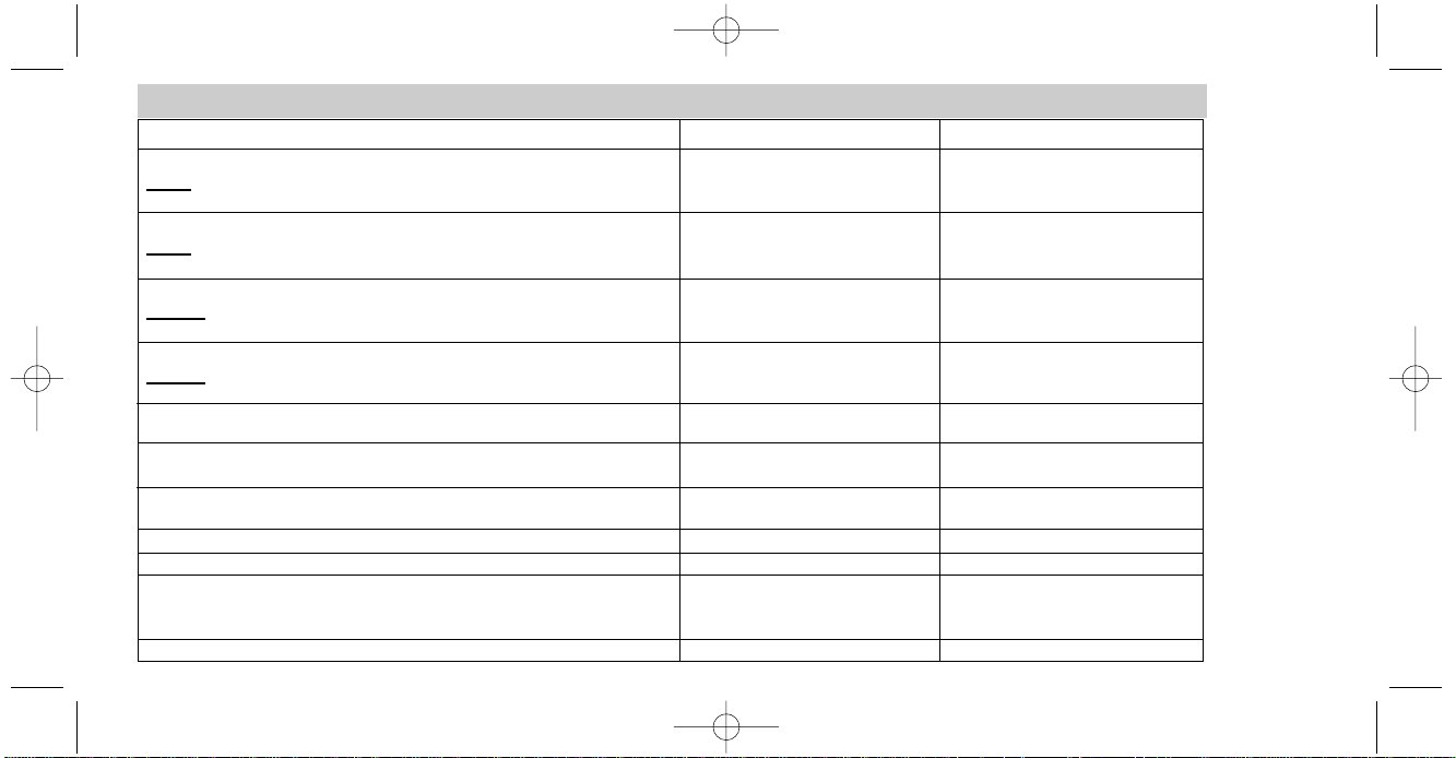
SPECIFICATIONS
EA2190490 Manual neu 31.07.2000 19:02 Uhr Seite 14
Page 15
15
Herzlichen Glückwunsch!
Wir gratulieren Ihnen zum Kauf eines EMPHASER Car-Amplifiers. Ein Produkt das für EMPHASER, Wyoming/USA hergestellt wird. Ausgestattet mit
einem kompromißlosen technischen Aufbau setzt diese Car-Amp Serie Maß-
stäbe bezüglich Leistungsabgabe, Klangqualität und Bedienungsfreundlichkeit.
Damit Sie die Wiedergabequalität und die Leistungsfähigkeit Ihres Verstär-
kers voll ausschöpfen können, möchten wir Sie bitten, sich eingehend mit den
Möglichkeiten und technischen Features dieser Verstärkerserie vertraut zu machen. Lesen Sie deshalb die nachfolgenden Abschnitte sorgfältig durch und
bewahren Sie diese Bedienungsanleitung für vielleicht später auftauchende
Fragen auf.
EMPHASER Car-HiFi Verstärker sind Produkte, die in Handarbeit mit höch-
sten Qualitätstandards und Kontrollen hergestellt werden. Sie werden Ihnen,
korrekte Installation vorausgesetzt, viele Jahre unvergleichlichen Hörspaß be-
reiten. Falls Sie weitere Fragen bezüglich der Anschlußmöglichkeiten des
Gerätes oder deren Installation haben, lassen Sie sich von Ihrem EMPHASER
Händler beraten.
Wichtig für IHREN Garantie-Schutz:
Wenn Sie den Einbau Ihres Auto-HiFi Systems selbst vornehmen, lassen Sie dieses von Ihrem Händler auf fachgerechte Installation überprüfen. Damit sichern Sie sich Ihre
Garantieleistungen und stellen sicher, daß die Anlage ihre
volle Klangqualität und Leistungsfähigkeit erreicht.
EA2190/EA490 BEDIENUNGS- UND INSTALLATIONSANLEITUNG
EA2190490 Manual neu 31.07.2000 19:02 Uhr Seite 15
Page 16
16
■ Kompromißloser Aufbau und Konstruktion durch ausschließ-
liche Verwendung von hochwertigen Materialien und elektrischen Bauteilen,
wie z.B. doppelseitige Glasfaser-Epoxyd-Harzplatinen oder hochstromfähige, hartvergoldete Strom- und Lautsprecheranschlußblöcke aus Massivmessing.
■ Integrierte elektronische Frequenzweiche mit separat schalt-
baren Hoch- und Tiefpass-Filtern mit jeweils 12 dB / Oktave Flankensteilheit.
Stufenlos regelbare Trennfrequenz(en) zwischen 50 bis 250 Hz.
■ Intelligente Schutzschaltung, erkennt Kurzschlüsse an den Laut-
sprecherausgängen, Gleichspannung im Ausgangssignal und überhöhte
Betriebstemperatur. Fehlerhafte Betriebszustände führen zum sofortigen
Abschalten des Gerätes.
■ Betriebsanzeige / Status- LED, zeigt Kurzschlüsse, elektrische
und thermische Überlastung des Verstärkers und Gleichspannung an den
Anschlußklemmen an.
■ 1 Ohm-Stabilität für den gleichzeitigen Anschluß von mehreren Laut-
sprechersystemen an einen Zwei- oder Vierkanalverstärker, oder für den
„Tri-Mode“ Betrieb. Enorme Leistungsreserven für niederohmige Lasten durch
den Einsatz eines geregelten MOSFET Netzteils. Brückbar für noch mehr
Ausgangsleistung z.B. für reinen Subwooferbetrieb.
■ Stereo, Mono-Bridged und Tri-Mode Betrieb ohne interne Um-
schaltung möglich.
■ Regelbare Eingangsempfindlichkeit mit einem breiten Einstell-
bereich von 150 mV bis 3 V. Ermöglicht dadurch die Kombination mit
prakt. allen Steuergeräten.
■ Soft Start / Soft Turnoff für sanftes Ein- und Ausschalten des Ver-
stärkers ohne Störgeräusche und Plops.
■ Leicht zugängliche Sicherung neben den Bedienungselementen.
TECHNISCHER AUFBAU / MERKMALE
EA2190490 Manual neu 31.07.2000 19:02 Uhr Seite 16
Page 17
17
Beschreibung der Bedienungselemente/Legende
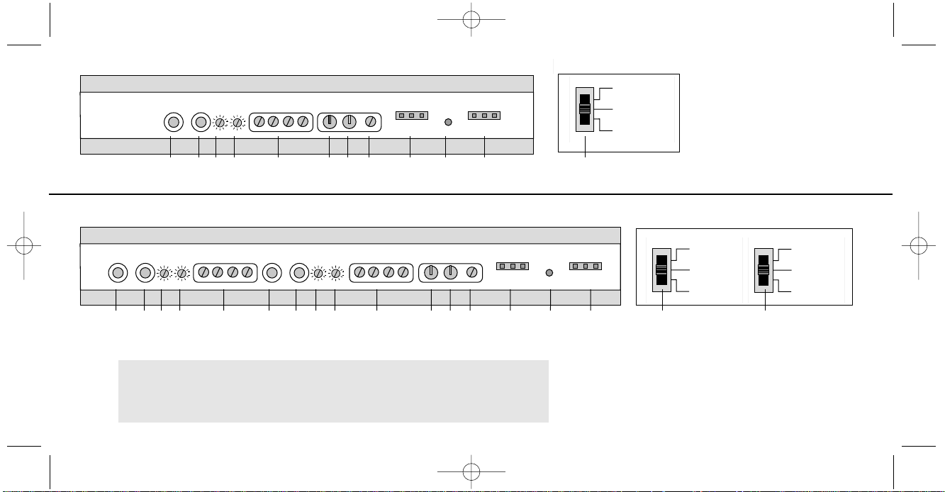
1.+2.Cinch Eingangsbuchsen („LEFT” & „RIGHT”; linker und rechter
Kanal). NF-Signal Eingang für den Anschluß des Steuergerätes
(siehe Abschnitt 2.6.1).
N.B. Beim Vierkanalmodell EA490 sind zwei Buchsenpaare vorhanden
(„FRONT“ und „REAR“).
3. Regler zum Einstellen der Trennfrequenz („FREQ. Hz”) der
integrierten aktiven Frequenzweiche (siehe Abschnitt 3.2).
4. Eingangsempfindlichkeitsregler („LEVEL”) für die Anpassung an die
Ausgangsspannung Ihres Steuergerätes (siehe Abschnitt 3.1).
5. Lautsprecheranschlußterminal („ L R ”) für den Anschluß
der Lautsprecher (siehe Abschnitt 2.6.2).
6. „GND” für den Anschluß an die Chassis-Masse des Kfz´s
(siehe Abschnitt 2.6.4).
7. „+12 V” für den Anschluß an die Autobatterie (siehe Abschnitt 2.6.3).
8. „REM” (Remote) Anschluß für die automatische
An-/Abschaltung des Verstärkers über den Rermote oder AntennaRemote Anschluß Ihres Steuergerätes (siehe Abschnitt 2.6.1).
9. „Fuse” (Sicherung) für die interne Absicherung des Verstärkers
gegen Überlastung und Fehlmanipulation.
10. Betriebszustands-LED „POWER PROTECTION” signalisiert den
Betriebszustand (siehe Abschnitt 2.6.5).
11. Schalter zur Betriebszustandswahl der integrierten aktiven
Frequenzweiche im Bodenblech (siehe Abschnitt 2.2).
BEDIENUNGSELEMENTE
EA2190490 Manual neu 31.07.2000 19:02 Uhr Seite 17
Page 18
18
5. – L + – R +
6. GND
7. +12V
8. REM
9. FUSE
10. LED POWER PROTECTION
11. High-/ Low-Pass Filter Setting
(siehe vorhergehende Seite)
1. Left
2. Right
3. FREQ. Hz
4. LEVEL
1 2 3 4 5 6 7 8 9 10 9
1 2 3 4 5 1 2 3 4 5 6 7 8 9 10 9
EMPHASER EA2190
FILTER SETTINGS
LOW PASS
FLAT
HIGH PASS
11
EMPHASER EA2190
Zweikanalendstufe
Bedienungselemente
Bodenblech
EMPHASER EA490
Vierkanalendstufe
Bedienungselemente
Bodenblech
EMPHASER EA490
11 11
FRONT FILTER SETTINGS REAR FILTER SETTINGS
LOW PASS
FLAT
HIGH PASS
LOW PASS
FLAT
HIGH PASS
EA2190490 Manual neu 31.07.2000 19:02 Uhr Seite 18
Page 19

19
2.1 Montageplan
Bevor Sie mit der Montage beginnen, erstellen Sie am besten eine kurze
Anschluß- und Installationsskizze. Zu berücksichtigen gilt es dabei hauptsächlich die Kabelverläufe und den Installationsort des Car-Amps. Beachten Sie
bitte, daß die Kabelführung sowie der Massepunkt einen entscheidenden Einfluß auf das störungsfreie Funktionieren Ihrer Anlage haben. Besondere Aufmerksamkeit verdient auch die korrekte Plazierung des Verstärkers (ausreichende Luftzufuhr), die richtige Stellung der Betriebsartschalter für den
Arbeitsbereich des Verstärkers, sowie die Qualität des verwendeten Zubehörs
zur fachgerechten Installation (Stromkabel, Cinchkabel, Sicherungshalter,
Verteilerblöcke, etc.).
2.2 Wählen der Betriebsart (Bodenblech)
Entsprechend dem Einsatzzweck des Car-Amps wählen Sie die Schalterstellung im Bodenblech des Verstärkers (siehe Abbildung im Abschnitt 1). Im
Falle des Zweikanalverstärkers EMPHASER EA2190 können jeweils drei
Betriebsarten gewählt werden:
■ Schalterstellung „FLAT“
Fullrangebetrieb, ideal für Soundboards oder große Hecksysteme
■ Schalterstellung „HPF“
Hochpassfilter schneidet Bässe ab. Ideal zum Ansteuern von Koax- und
Komponentensystemen.
■ Schalterstellung „LPF“
Tiefpassfilter schneidet alle Frequenzen außer die Bässe ab. Ideal für den
Betrieb von Subwoofern.
Während der Zweikanalverstärker EMPHASER EA2190 über nur einen Schalter zur Betriebsartwahl verfügen, besitzt das Vierkanalmodell EMPHASER
EA490 zwei Schalter im Bodenblech.
■ Schalterstellung für „FRONT“ LPF, Flat, HPF
■ Schalterstellung für „REAR“ LPF, Flat, HPF
Es kann also mit der Vierkanalendstufe EA490 ein vollaktives Subwoofer-/
Satelliten-System, bestehend z.B. aus einem Paar Komponentenlautsprecher
vorne im Türbereich und einem Subwoofer hinten im Kofferraum realisiert
werden. Dazu werden die Schalter im Bodenblech auf HPF („Front“) und
auf LPF („Rear“) gestellt. Das mit „Front“ bezeichnete Cinchbuchsenpaar mit
dem dazugehörigen Lautsprecheranschlußblock treibt dabei das Frontsystem,
die mit „Rear“ bezeichneten Cincheingänge und LS-Ausgänge den Subwoofer. Falls Ihr Steuergerät nur über einen Cinchausgang verfügt, können
Sie die Aufteilung des NF-Signals auf den Front und Rear Eingang mittels
Y-Adaptern vornehmen.
INSTALLATION
EA2190490 Manual neu 31.07.2000 19:02 Uhr Seite 19
Page 20
20
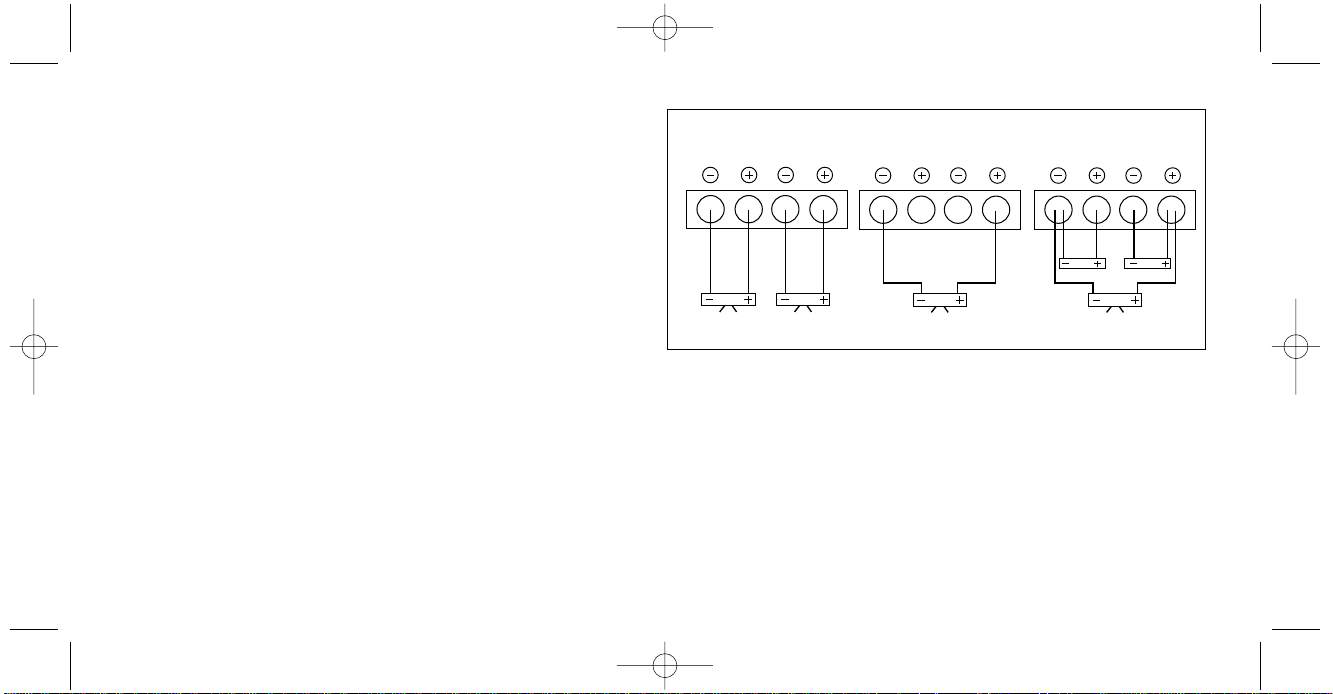
2.3 Stereo, Bridged-Mono und Tri-Mode Betrieb
Jeweils linker und rechter Kanal der Verstärker können für den Einsatz als
Subwoofer-Endstufe Mono „abgegriffen“ (gebrückt) werden. Dies wird durch
entsprechende Lautsprecheranschlußbelegung ermöglicht (siehe separates
Anschlusschema). Beim Mono (Bridged) Betrieb steht ca. die dreifache
Kanalleistung am Lautsprecherausgang zur Verfügung. Es sind Impedanzen von minimal 2 Ohm (zwei 4 Ohm Subwoofer parallel geschaltet) im
Brückenbetrieb zulässig. Tri-Modebetrieb beschreibt den gleichzeitigen
Anschluß eines Stereo-Lautsprecherpaares am normalen Lautsprecherausgang mit einem zusätzlich am gleichen Lautsprecherausgang angeschlossenen Subwoofer. Für diese Betriebsart (siehe auch separates Diagram)
empfehlen wir Ihnen eine entsprechende Tri-Mode Weiche (passiv) zu verwenden. Des weiteren sollten alle eingesetzten Lautsprecher eine MinimumImpedanz von 4 Ohm aufweisen.
2.4 Einbauort
Der Verstärker muß unbedingt gut plaziert und im Interesse der passiven
Sicherheit stabil befestigt werden. Prüfen Sie ob die gewählte Montagefläche
eben und stabil genug zur sicheren Befestigung des schweren Verstärkers ist.
Als Montageort eignet sich z.B. ein Platz im Kofferraum oder unter dem Fahrer- oder Beifahrersitz, bzw. jeder andere Ort, der eine saubere Installation
ermöglicht. Stellen Sie, eine ausreichende Belüftung sicher (mindestens
5 cm Freiraum oberhalb und auf den Seiten der Alu-Kühlkörper Rippen). Vermeiden Sie Montageorte mit „unbekanntem Hintergrund“. Es könnten sich
ein Benzintank, hydraulische Bremsleitungen, Kabel etc. dahinter verbergen!
Achten Sie auch auf einen trocken, gegen mechanische Einwirkungen geschützten Installationsort, der auch nach der Endmontage noch für die Bedienung und Einstellung des Verstärkers gut zugänglich ist.
R
L
STEREO
R
L
BRIDGED-MONO
R
L
TRIMODE
Lautsprecher-Betriebsarten
EA2190490 Manual neu 31.07.2000 19:02 Uhr Seite 20
Page 21
21
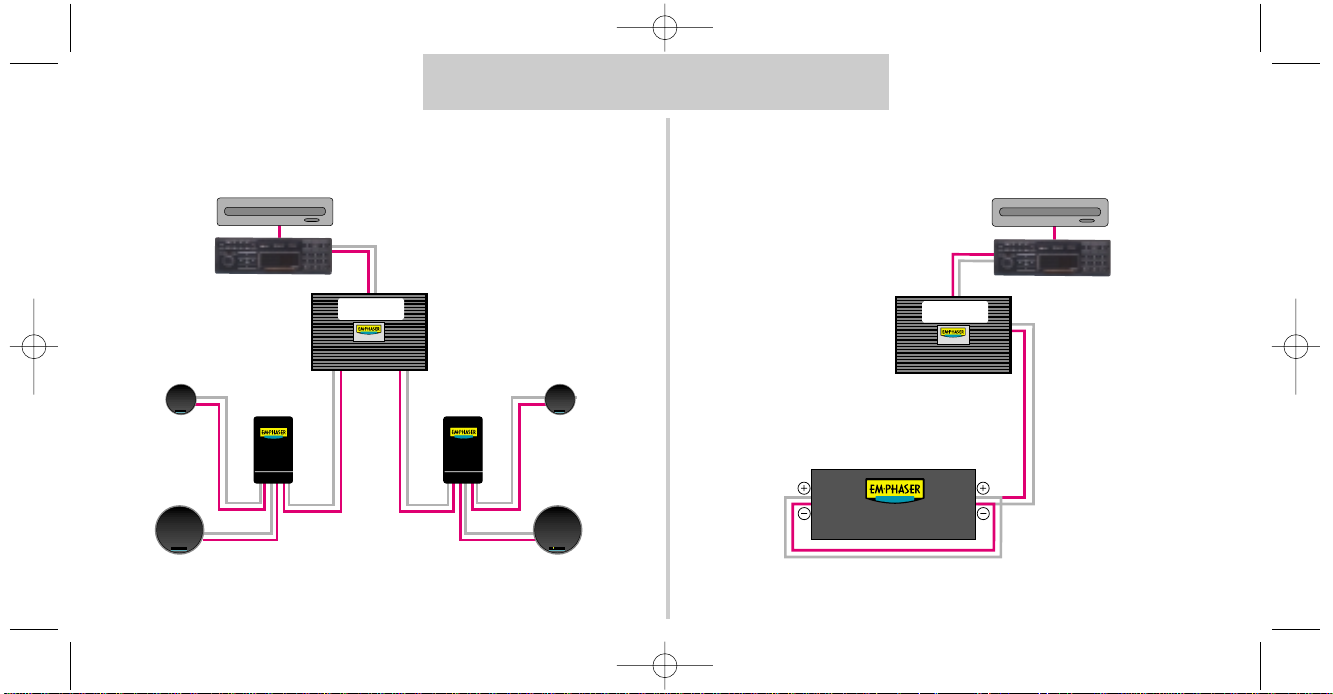
KONFIGURATIONSVORSCHLÄGE EA2190
2-Kanal Mono
Great American Car Audio
Great American Car Audio
Great American Car Audio
Great American Car Audio
CD-WECHSLER
STEUERGERÄT
PRE-OUT „REAR”
WEICHE
PASSIV
WEICHE
PASSIV
HOCHTÖNER
BASS-MITTELTÖNER
EA2190
HOCHTÖNER
BASS-MITTELTÖNER
PRE-OUT ”FRONT”
CD-WECHSLER
STEUERGERÄT
PRE-OUT „REAR”
EA2190
PRE-OUT ”FRONT”
SUBWOOFER PARALLEL (2 Ω)
EA2190490 Manual neu 31.07.2000 19:02 Uhr Seite 21
Page 22
Great American Car Audio
Great American Car Audio
Great American Car Audio
Great American Car Audio
Great American Car Audio
Great American Car Audio
Great American Car Audio Great American Car Audio
BASS-MITTELTÖNER
CD-WECHSLER
STEUERGERÄT
WEICHE
PASSIV
WEICHE
PASSIV
HOCHTÖNER
WEICHE
PASSIV
WEICHE
PASSIV
BASS-MITTELTÖNER
HOCHTÖNER
EA490
HOCHTÖNER
BASS-MITTELTÖNER
BASS-MITTELTÖNER
HOCHTÖNER
22
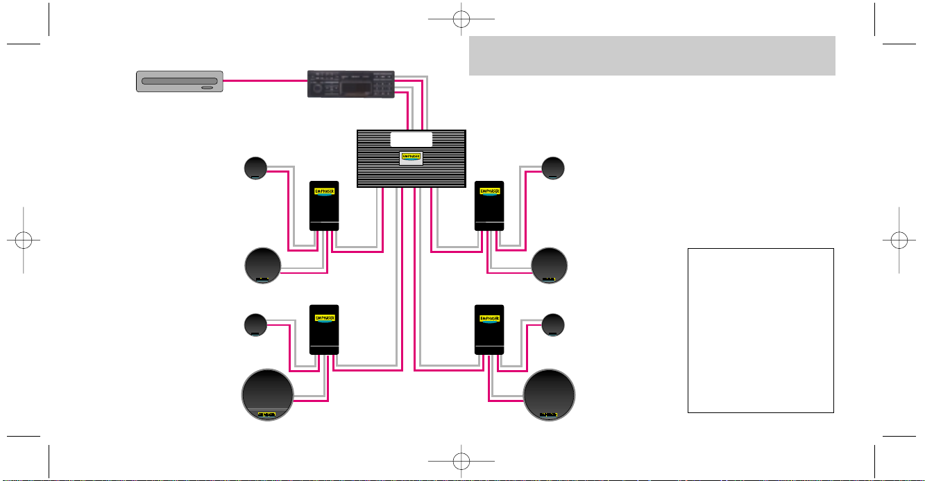
ACHTUNG!
In dieser Konfiguration
kann die 4-kanalige EA490
wie folgt eingesetzt werden:
– HPF („High-Pass”) -Betrieb
für „FRONT” (vorne) und
– ‘Fullrange’ („FLAT”) für
„REAR” (hinten)
oder
–‘Fullrange’-Betrieb („FLAT”)
für „FRONT” & „REAR”
KONFIGURATIONSVORSCHLAG EA490
EA2190490 Manual neu 31.07.2000 19:02 Uhr Seite 22
Page 23

23
2.5 Befestigung des Verstärkers
Halten Sie den Verstärker an den gewünschten Ort und markieren Sie mit einem geeigneten Filzstift die Bohrposition der vier Befestigungslöcher. Mit der
gebotenen Vorsicht bohren Sie nun die angezeichneten Löcher mit einem
2,5 oder 3 mm Bohrer. Drücken Sie die beigelegten Gummitüllen in die
Befestigungslöcher Ihres Verstärkers!! Ein Masseschluß des Verstärkergehäuses
auf die Kfz-Masse muß unbedingt vermieden werden! (Brummschleife!)
Legen Sie nun den Verstärker auf die vorgebohrten Löcher und stecken Sie
die Schrauben von oben in die Befestigungslöcher des Verstärkers. Ziehen Sie
die Schrauben gleichmäßig an und überprüfen Sie abschließend den einwandfreien Sitz des Verstärkers.
2.6 Verkabelung/Elektrischer Anschluß
ACHTUNG!
Entfernen Sie – bevor Sie die Verkabelung in Angriff nehmen
– das Pluskabel vom Pluspol der Batterie!
Bei allen nachfolgend beschriebenen Installationsschritten muß der Stromkreis des Kraftfahrzeugs unterbrochen sein! Erst nach Abschluß aller Instal
-
lationsarbeiten wir
d über die Hauptsicherung der Stromkreis geschlossen!
Einige Tips!
■ Verwenden Sie beim Einziehen der Stromkabel entsprechende Kabeltüllen
aus Gummi um ein Durchscheuern der Isolation an Blechkanten, respektive
den dadurch resultierenden Kurzschluß auf Chassismasse zu vermeiden.
■ Speziell die musiksignalführenden (Cinch-) Kabel müssen soweit wie mög-
lich von allen potentiellen „elektrischen Störsendern“ wie Bordcomputer, Benzinpumpe, Stromversorgungskabel für die Beleuchtung, etc. verlegt werden.
2.6.1 Verlegen Sie das Cinchkabel und das Remote-Kabel
vom Steuergerät zur Endstufe. Diese Kabel sollten unbedingt räumlich getrennt von der Stromzuführung des Verstärkers eingezogen werden. Verwenden Sie nur mindestens doppelt oder dreifach geschirmte Kabel! Schließen
Sie das Remote-Kabel an das mit Antenna-Rem. oder Amplifier-Rem. bezeichnete Kabel Ihres Steuergerätes an. Anschließend stecken Sie die Cinchkabel in die Cincheingangsbuchsen des Verstärkers ein.
2.6.2 Schließen Sie die Lautsprecherkabel an. Verwenden Sie Lautsprecherkabel mit mindestens 1,5 mm
2
, besser aber 2,5 mm2Querschnitt.
Entfernen Sie ca. 8 mm der Isolierung des LS-Kabels und beachten Sie
beim Anschluss unbedingt die richtige Polung der Lautsprecherkabel (Plus auf Plus, Minus auf Minus). Ziehen Sie die LS-
Schraubklemmen satt an.
EA2190490 Manual neu 31.07.2000 19:02 Uhr Seite 23
Page 24

24
EINSTELLUNGEN
2.6.3 Verlegen Sie nun das Pluskabel direkt von der Batterie
zum Verstärker. Innerhalb der ersten 30 cm nach dem Pluspolklemmen-
abgriff muß eine Hauptsicherung angebracht werden (Absicherung des Pluskabels gegen Kabelbrand wegen Kurzschluß auf Masse!) Verwenden Sie eine
dem Stromkabelquerschnitt entsprechende Sicherung. Lassen Sie sich von
Ihrem Händler beraten. Setzen Sie die Sicher
ung erst nach Abschluß aller
Installationsarbeiten in den Sicherungshalter ein!
2.6.4 Nun schließen Sie das Minuskabel am Verstärker an.
Versuchen Sie dieses Kabel so kurz wie möglich zu halten. Es sollte den
gleichen Querschnitt wie das Pluskabel besitzen. Verwenden Sie für den Massepunktanschluß einen vergoldeten Ringkabelschuh, und achten Sie
auf eine perfekt gesäuberte blanke Metalloberfläche (schlech-
te Massepunkte sind für über 90% aller Fälle der auftretenden Störungen verantwortlich). Ein schlechter Massepunkt bedeutet nicht nur erhöhte Störungsanfälligkeit, sondern auch drastisch reduzierte Ausgangsleistung (durch früh
einsetzende Verzerrungen).
2.6.5 Schließen Sie nun den Stromkreis zum Verstärker durch
das Einsetzen der Hauptsicherung. Ihr Autoverstärker sollte nun beim
Einschalten des Steuergerätes durch Aufleuchten der grünen LED die Betriebsbereitschaft anzeigen. Leuchtet die LED rot auf, ist Ihre Installation fehlerhaft. Gehen Sie die Installationsanweisungen von Abschnitt 2.6.1 bis 2.6.5
nochmals genau durch.
3.1 Eingangsempfindlichkeitsanpassung
Die korrekte Eingangsempfindlichkeitseinstellung ist wichtig für die Ausnutzung des optimalen Dynamikspielraumes Ihrer Steuergerät / Verstärker /
Lautsprecherkombination. Diese Empfindlichkeitseinstellung beeinflußt das
Grundrauschen ebenso, wie die verzerrungsfrei erzielbare Maximallautstärke.
Einstelltips: Drehen Sie den (die) „LEVEL“ Regler an Ihrem Verstärker im
Gegenuhrzeigersinn in die Minimumposition. Stellen Sie den Lautstärkereg-
ler Ihres Steuergerätes auf ca. 3/4 der Maximallautstärke, und benutzen Sie
für die nun kommende Einstellung ein gut aufgenommenes dynamikreiches
Musikstück. Drehen Sie nun den „LEVEL“ Regler Ihres Verstärkers langsam im
Uhrzeigersinn auf, bis Sie gerade die Verzerrungsgrenze erreichen. Dann
drehen Sie den Regler gerade soweit zurück, daß die Verzerrungen wieder
verschwinden. Beim Vierkanalmodell EA490 (und Einsatz als Sat/Sub Verstärker!) drehen Sie den „Rear“ „LEVEL“ Regler (Subwoofer) auf 3/4 bis
voll auf, und „dosieren“ die Lautstärke des Mittelhochtonbereiches mit dem
„LEVEL“ Regler des „Front“ Kanals dazu. Der anschließend in Abschnitt 3.2
folgende Abgleich der Trennfrequenzen der integrierten Aktivweiche bedingt
einen nochmaligen Feinabgleich der „Front“ Eingangsempfindlichkeit.
EA2190490 Manual neu 31.07.2000 19:02 Uhr Seite 24
Page 25

25
3.2 Frequenzweicheneinstellung
Die jeweils separat schaltbare Hochpass-/ Tiefpassfunktion der integrierten
Frequenzweiche Ihres Verstärkers kann zum Ansteuern eines Subwoofers, eines Koax- oder Komponentensystems, oder im Falle der Vierkanalendstufe
EA490 sogar zum Ansteuern eines kompletten Soundsystems bestehend
aus einem Paar Satelliten und einem Subwoofer verwendet werden. Mit der
Einstellung der Trennfrequenz des Hochpasses (HPF) soll eine elektrische und
mechanische Entlastung der verwendeten Coax- oder Componentensysteme
erfolgen. Je nach der vorhandenen Membranfläche und Nennbelastbarkeit
der verwendeten (Satelliten)-Systeme empfiehlt sich eine Trennfrequenz im
Bereich zwischen 50 bis 250 Hz. Diese Einstellung kann über den „FREQ-Hz“
Regler vorgenommen werden. Die Abstimmung sollte gehörmäßig erfolgen
und orientiert sich an der Midbasswiedergabe und der gewünschten Pegelfestigkeit der „Satelliten“. Dabei führt eine zu tief gewählte Trennfrequenz zu
einer guten Midbasswiedergabe, schränkt aber die Pegelfestigkeit stark
ein. Eine zu hohe Trennfrequenzeinstellung hat einen „dünnen“ Klang mit guter Pegelfestigkeit zur Folge. Suchen Sie einen dem Einsatzzweck, der Belastbarkeit der verwendeten Lautsprecher und Ihrem Geschmack angepaß-
ten Kompromiß. Wenn Sie Ihren (2-Kanal) Verstärker zum Antrieb eines Subwoofers verwenden, sollte die zu wählende Trennfrequenz des Tiefpasses (LPF)
sinnvollerweise im Bereich zwischen 50 und 90 Hz liegen. Justieren Sie den
„FREQ. Hz“ Regler so, daß der Bass satt und trocken mit genügend Tiefbass-
anteil wiedergegeben wird. Eine zu tiefe Trennfrequenz läßt den Bassbereich
kraftlos und unkonturiert wirken. Eine zu hohe Trennfrequenz bewirkt ein
Dröhnen des Bassbereichs.
EA2190490 Manual neu 31.07.2000 19:02 Uhr Seite 25
Page 26
26
Nennausgangsleistung
Ster
eo an 4 Ohm (13.8 V)
(THD = 1 %)
RMS-Leistung
Ster
eo an 2 Ohm(13.8 V)
(THD < = 0,1 %)
RMS-Leistung
gebrückt
an 4 Ohm (13.8 V)
(THD < = 0,1 %)
RMS-Leistung
gebrückt
an 2 Ohm (13.8 V)
(THD < = 0,1 %)
Dämpfungsfaktor
an 4 Ohm
Geräuschspannungsabstand
(A-Filter)
Frequenzgang
(+0 dB / -1 dB)
Kanaltrennung
Eingangsempfindlichkeit
Integrierte Frequenzweiche
Flankensteilheit
Trennfrequenz
Sicherung
2 x 190 W
2 x 290 W
1 x 600 W
Sicherung brennt durch
200
< 90 dB
10 Hz - 40 kHz
< 55 dB
150 mV - 3 V
HPF/LPF
12 dB/oct.
stufenlos regelbar 50 -250 Hz
2 x 30 A
EA2190
4 x 90 W
4 x 120 W
2 x 240 W
Sicherung brennt durch
200
< 90 dB
10 Hz - 40 kHz
< 55 dB
150 mV - 3 V
HPF/LPF
12 dB/oct.
stufenlos regelbar 50 -250 Hz
2 x 30 A
EA490
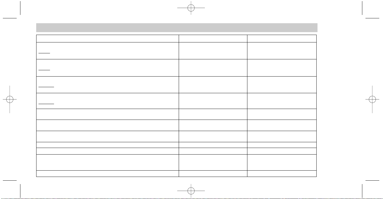
TECHNISCHE DATEN
EA2190490 Manual neu 31.07.2000 19:02 Uhr Seite 26
Page 27

27
WARRANTY POLICY GARANTIEBESTIMMUNGEN
Important!
Dear customer
Thank you for buying this EMPHASER amplifier. It is advizable to keep the orginal packing
material for any future transporting of the product. Please read the warranty specifications
below carefully. Should your EMPHASER product require warranty service, please return it
to the retailer from whom it was purchased or
the distrubutor in your country. Please do not
send any product to EMPHASER Inc. U.S.A. or
ACR AG, Switzerland. Should you have difficulty in finding an authorized EMPHASER service center, details are available from your
local distributor or from the ACR AG address
below.
EMPHASER Limited Warranty
The EMPHASER amplifier listed overleaf is fully warranted against defective materials or
workmanship for a period of One Year from
date of purchase. Warranty work will not
be carried out unless this warranty
certificate is presented fully completed with model, serial nummer, purchaser’s
address, purschasing date and dealer stamp
together with the original sales slip and eit-
her an authorized dealer’s confirma-
tion of installation or authorized dealer’s installation approval!
Warranty Limitations
This warranty does not cover any damage due
to:
1. Unauthorized or unapproved installation,
incorrect audio or power connection(s).
2. Exposure to excessive humidity, fluids,
heat, sunrays or excessive dirt or dust.
3. Accidents or abuse, unauthorized repair attempts and modifications not explicitly authorized by the manufacturer.
This warranty is limited to the repair or the
replacement of the defective product at the manufacturer’s option and does not include include any other form of damage, whether incitential, consequential or otherwise. The warranty does not cover any transport costs or damages caused by transport or shipment of
the product.
Wichtig!
Sehr geehrter Kunde, sehr geehrte Kundin Vielen Dank, daß Sie sich zum Kauf eines EMPHASER Verstärkers entschlossen haben. Wir
möchten Sie bitten, die Originalverpackung für
einen allfälligen Transport aufzuheben und die
untenstehenden Garantie-Bestimmungen genau durchzulesen. Sollten Sie für Ihren Verstärker Garantie-Leistungen beanspruchen,
wenden Sie sich bitte direkt an den Händler,
bei dem Sie das Gerät gekauft haben. Bitte senden Sie keine Geräte an EMPHASER Inc. U.S.A.
oder an ACR AG. Bei Schwierigkeiten, ein geeignetes EMPHASER Service-Center zu finden,
erhalten Sie bei ACR AG
in CH-5330 Zurzach
weitere Informationen.
EMPHASER Garantie-Bestimmungen
Der Hersteller gewährleistet auf den umseitig
aufgeführten EMPHASER-Verstärker für den
Fall von Material- oder Herstellungsfehlern ein
Jahr Garantie. Garantieansprüche
können nur mit einer korrekt und vollständig ausgefüllten Garantie-Karte
zusammen mit dem Original-Kaufbeleg und
einer Bescheinigung
über den autorisierten Einbau bzw. dem Prüfungsnachweis eines autorisierten Händ-
lers über den korrekten Selbst-Einbau
(„Installation Approved“) geltend gemacht
werden!
Garantie Einschränkungen
Nicht unter Garantie fallen Schäden infolge
von:
1. nicht-autorisierter bzw. nicht vom autorisierten Händler/lnstallateur geprüftem SelbstEinbau oder inkorrekten Audio- oder Stromanschlüssen.
2. schädlichen Einwirkungen von übermässi-
ger Feuchtigkeit, Flüssigkeiten, Hitze, Sonneneinstrahlung oder übermässiger Verschmutzung.
3. mechanischer Beschädigung durch Unfall,
Fall oder Stoss; Schäden durch nicht autorisierte Reparaturversuche oder nicht durch den
Hersteller ausdrücklich autorisierte Modifikationen.
Die Garantie dieses Produkts bleibt in jedem
Fall auf die Reparatur bzw. den Ersatz (Entscheidung beim Hersteller) des jeweiligen EMPHASER-Produkts beschränkt. Schäden durch
unsachgemässe Verpackung oder Transportschäden werden nicht durch diese Garantie
gedeckt. Jeder über diese Garantie Erklärung
hinausgehende Anspruch und jede Haftung für
direkte oder indirekte Folgeschäden werden
ausdrücklich abgelehnt.
EA2190490 Manual neu 31.07.2000 19:02 Uhr Seite 27
Page 28
WARRANTY CERTIFICATE
Model name:
POWER AMPLIFIER EA 2190 / EA 490
Serial Number:
Date of purchase:
Your name:
Your address:
City:
State: ZIP or Postal Code:
Country:
Your phone number:
Limited Warranty: 12 Months
(Valid with authorized Installation Approval only)
Your EMPHASER Dealer:
❏ Installed by
authorized dealer
Installation date:
Inspected and
approved by:
Installation Approval
❏ Installed by
customer
EMPHASER Inc.,
Wyoming, Michigan, U.S.A.
EA2190490 Manual neu 31.07.2000 19:02 Uhr Seite 28
 Loading...