

Page 1
6-CHANNEL POWER AMPLIFIER
INSTALLATION & OPERATING MANUAL
EINBAU- & BEDIENUNGSANLEITUNG
EA 6-CH Manual 12.03.2002 13:31 Uhr Seite 1
Page 2

2
CONTENTS
1. EA 4100-500 DESIGN FEATURES . . . . . . . . . . . . . . . . . . . . . . . . . . . . . . . . . . . . . . . . 5
2. CONNECTIONS & CONTROLS . . . . . . . . . . . . . . . . . . . . . . . . . . . . . . . . . . . . . . . . . 6-8
2.1 FRONT PANEL CONNECTION & CONTROLS . . . . . . . . . . . . . . . . . . . . . . . . . . . . . . 6/7
2.2 REAR PANEL CONNECTIONS & CONTROLS . . . . . . . . . . . . . . . . . . . . . . . . . . . . . . . . .8
3. INSTALLATION PLANNING . . . . . . . . . . . . . . . . . . . . . . . . . . . . . . . . . . . . . . . . . . . . . .9
3.1 PLAN OF ATTACK . . . . . . . . . . . . . . . . . . . . . . . . . . . . . . . . . . . . . . . . . . . . . . . . . . . .9
3.2 MOUNTING LOCATION . . . . . . . . . . . . . . . . . . . . . . . . . . . . . . . . . . . . . . . . . . . . . . .9
4. GENERAL INFO ABOUT WIRE CROSS SECTIONS AND CABLE QUALITY . . . . . . . . . . . . .10
4.1 MAIN POWER CABLE CROSS SECTION . . . . . . . . . . . . . . . . . . . . . . . . . . . . . . . . . . .10
4.2 RCA INTERCONNECTS . . . . . . . . . . . . . . . . . . . . . . . . . . . . . . . . . . . . . . . . . . . . . . .10
4.2 LOUDSPEAKER CABLES . . . . . . . . . . . . . . . . . . . . . . . . . . . . . . . . . . . . . . . . . . . . . . .10
4.3 MINIMUM SPEAKER IMPEDANCES . . . . . . . . . . . . . . . . . . . . . . . . . . . . . . . . . . . . . . .10
5. AMPLIFIER MOUNTING . . . . . . . . . . . . . . . . . . . . . . . . . . . . . . . . . . . . . . . . . . . . . . .10
6. CABLE ROUTING . . . . . . . . . . . . . . . . . . . . . . . . . . . . . . . . . . . . . . . . . . . . . . . . . . . .11
6.1 RCA INTERCONNECTS AND REMOTE WIRING . . . . . . . . . . . . . . . . . . . . . . . . . . . . . .11
6.2 CONNECTION OF LOUDSPEAKER WIRES . . . . . . . . . . . . . . . . . . . . . . . . . . . . . . . . . .11
6.3 MAIN POWER CABLE ROUTING . . . . . . . . . . . . . . . . . . . . . . . . . . . . . . . . . . . . . . . . .11
6.4 SYSTEM CONFIGURATIONS . . . . . . . . . . . . . . . . . . . . . . . . . . . . . . . . . . . . . . . . .12-14
7. ADJUSTMENT OF THE CONTROL FUNCTIONS . . . . . . . . . . . . . . . . . . . . . . . . . . . .15-18
7.1 SELECTING THE OPERATION MODE FOR 1/2CH & 3/4CH . . . . . . . . . . . . . . . . . . . . . .15
7.2 SELECTING A CROSSOVER FREQUENCY POINT FOR SATELLITE SPEAKERS . . . . . . . . . . .15
7.3 SELECTING A CROSSOVER FREQUENCY POINT FOR THE KICKBASS SPEAKERS . . . . . . .16
7.4 LOWPASS CROSSOVER FREQUENCY ADJUSTMENTS FOR THE SUBWOOFER . . . . . . . .16
7.5 SUBSONIC CROSSOVER FREQUENCY ADJUSTMENT FOR THE SUBWOOFER . . . . . . . . .17
7.6 ADJUSTMENT OF THE INPUT GAIN CONTROLS . . . . . . . . . . . . . . . . . . . . . . . . . . . . . .17
7.7 PHASE SHIFT CONTROL . . . . . . . . . . . . . . . . . . . . . . . . . . . . . . . . . . . . . . . . . . . . . . .18
8. TECHNICAL SPECIFICATIONS . . . . . . . . . . . . . . . . . . . . . . . . . . . . . . . . . . . . . . . . . . .30
9. EMPHASER LIMITED WARRANTY . . . . . . . . . . . . . . . . . . . . . . . . . . . . . . . . . . . . . . . . .31
9.1 WARRANTY LIMITATIONS . . . . . . . . . . . . . . . . . . . . . . . . . . . . . . . . . . . . . . . . . . . . .31
10. WARRANTY CARD . . . . . . . . . . . . . . . . . . . . . . . . . . . . . . . . . . . . . . . . . . . . . . . . . .32
EA 6-CH Manual 12.03.2002 13:31 Uhr Seite 2
Page 3

3
INHALT
1. TECHNISCHER AUFBAU / MERKMALE . . . . . . . . . . . . . . . . . . . . . . . . . . . . . . . . . . . . .20
2. ANSCHLÜSSE & BEDIENUNGSELEMENTE . . . . . . . . . . . . . . . . . . . . . . . . . . . . . . . .21-23
2.1. EINGÄNGE & FUNKTIONEN AM FRONT PANEL . . . . . . . . . . . . . . . . . . . . . . . . . .21/22
2.2 EINGÄNGE & FUNKTIONEN AM REAR PANEL . . . . . . . . . . . . . . . . . . . . . . . . . . . . . .23
3. PLANUNG DER INSTALLATION . . . . . . . . . . . . . . . . . . . . . . . . . . . . . . . . . . . . . . . . . .24
3.1 MONTAGEORT . . . . . . . . . . . . . . . . . . . . . . . . . . . . . . . . . . . . . . . . . . . . . . . . . . . . .24
4. INFO'S ZU DEN KABELQUERSCHNITTEN & QUALITÄT . . . . . . . . . . . . . . . . . . . . . . . . .25
4.1 STROMKABEL QUERSCHNITT . . . . . . . . . . . . . . . . . . . . . . . . . . . . . . . . . . . . . . . . . . .25
4.2 CINCHKABEL . . . . . . . . . . . . . . . . . . . . . . . . . . . . . . . . . . . . . . . . . . . . . . . . . . . . . .25
4.3 LAUTSPERCHER KABEL . . . . . . . . . . . . . . . . . . . . . . . . . . . . . . . . . . . . . . . . . . . . . . . .25
4.4 MINIMALE LASTIMPEDANZ DER LAUTSPRECHER . . . . . . . . . . . . . . . . . . . . . . . . . . . . .25
5. MONTAGE DES VERSTÄRKERS . . . . . . . . . . . . . . . . . . . . . . . . . . . . . . . . . . . . . . . . . .25
6. VERKABELUNG / ELEKTRISCHER ANSCHLUSS . . . . . . . . . . . . . . . . . . . . . . . . . . . . . . .25
6.1 VERLEGEN VON CINCH- UND REMOTE KABELN . . . . . . . . . . . . . . . . . . . . . . . . . . . . .26
6.2 ANSCHLUSS DER LAUTSPRECHERKABEL . . . . . . . . . . . . . . . . . . . . . . . . . . . . . . . . . . .26
6.3 VERLEGEN UND ANSCHLUSS DER HAUPT-STROMKABEL . . . . . . . . . . . . . . . . . . . . . . .26
7. EINSTELLUNGEN AN DER FREQUENZWEICHE . . . . . . . . . . . . . . . . . . . . . . . . . . . .27-29
7.1 WAHL DES "OPERATING MODES" DER FREQUENZWEICHE . . . . . . . . . . . . . . . . . . . . .27
7.2 WAHL DER TRENNFREQUENZ FÜR DIE SATELLITENSYSTEME . . . . . . . . . . . . . . . . . . . . .27
7.3 WAHL DER TRENNFREQUENZEN FÜR EIN KICKBASS-SYSTEM . . . . . . . . . . . . . . . . . . . .28
7.4 LOWPASS EINSTELLUNG FÜR DEN SUBWOOFER . . . . . . . . . . . . . . . . . . . . . . . . . . . . .28
7.5 SUBSONIC HOCHPASS TRENNFREQUENZ FÜR DEN SUBWOOFER . . . . . . . . . . . . . . . .28
7.6 ANPASSUNG DER EINGANGSEMPFINDLICHKEIT . . . . . . . . . . . . . . . . . . . . . . . . . . . . .29
7.7 EINSTELLUNG DES PHASE SHIFTS . . . . . . . . . . . . . . . . . . . . . . . . . . . . . . . . . . . . . . . .29
8. TECHNICAL SPECIFICATIONS . . . . . . . . . . . . . . . . . . . . . . . . . . . . . . . . . . . . . . . . . . .30
9. EMPHASER GARANTIE-BESTIMMUNGEN . . . . . . . . . . . . . . . . . . . . . . . . . . . . . . . . . .31
9.1 GARANTIE-EINSCHRÄNKUNGEN . . . . . . . . . . . . . . . . . . . . . . . . . . . . . . . . . . . . . . . .31
10. GARANTIEKARTE . . . . . . . . . . . . . . . . . . . . . . . . . . . . . . . . . . . . . . . . . . . . . . . . . . .32
EA 6-CH Manual 12.03.2002 13:31 Uhr Seite 3
Page 4
4
Congratulations!
And thank you for choosing this EMPHASER 6-channel car audio amplifier! You now own a product
of uncompromising engineering philosophy, meticulous craftsmanship and unprecedented functionality.
To maximize the performance of this amplifier and your car audio system install, we recommend that
you acquaint yourself thoroughly with all capabilities and features of this EMPHASER amplifier unit.
Please read this manual carefully, before attempting the installation of this amplifier. Please retain this
manual and your purchasing / installation receipts for future reference.
IMPORTANT NOTICE:
In case you are installing your EMPHASER amplifier yourself, you should
have your installation checked and approved by an authorized professional
EMPHASER dealer/installer in order, to qualify for full warranty protection
and also, to reach maximum power- and audio performance possible with
your individual car audio system.
Prolonged listening at high levels may result in hearing loss! Please exercise caution to prevent hearing damage.
EA 6-CH Manual 12.03.2002 13:31 Uhr Seite 4
Page 5

5
1. EA 4100-500 DESIGN FEATURES
■ 6-CHANNEL AMPLIFIER: The EA 4100-500 allows the cross-over controlled amplification of a
twin satellite/subwoofer or satellite / kickwoofer / subwoofer car audio system, without the need for
two or more amplifiers, and or an additional external active crossover
■ DASH-MOUNT REMOTE LOWPASS LEVEL CONTROL: The EA 4100-500 comes complete
with a compact remote "Lowpass-Level" control unit, which can be conveniently mounted on or under
the dashboard of your car. This control device allows the individual level adjustment of the volume level
(applicable for the lowpass operated channels 5/6 only)
■ TWO INDEPENDENT MOSFET POWER SUPPLIES: The EA4100-500 features independent
power supplies for "satellite" and subwoofer channels, to prevent unwanted interference between the
two amplifier sections
■ 1 OHM IMPEDANCE LOAD STABILITY: All channels of this amplifier are 1 ohm stable.
Furthermore, the output stage layout provides a very high damping factor and thus, the amplifier will
give you a very precise reproduction of any music material
■ INTEGRATED ELECTRONIC FREQUENCY FILTERING CONTROLS: All three crossover sec-
tions are totally independent and feature individually adjustable highpass, lowpass or bandpass filtering, as well as fulllrange loop through. All internal active filters feature crossover slope rates of 12
dB/octave
■ UNCOMPROMISING DESIGN AND CONSTRUCTION: Only best electrical and electronic
components found their way into this amplifier, for example double-sided glass-fiber epoxy circuit
boards equipped with high current output devices. The power input side features molded 35mm
2
ter-
minals for full unrestricted current flow
■ ADVANCED PROTECTION CIRCUITRY: The protection circuitry safe-guards the amplifier from
short-circuits at the speaker outputs, DC offset voltage at the outputs and overheating of power electronics
■ STATUS AND PROTECTION LED'S: A green and a red LED enable you to easily monitor the
operating status of your EA4100-500 amplifier. The LED's are signaling normal operation and problems, such as short-circuits, electrical or thermal overload and DC voltage at the speaker outputs
■ ADJUSTABLE INPUT SENSITIVITY: Each RCA line-input pair accepts input voltages from
200mV to 9V, providing a good match to the line-output levels of almost any head-unit on the market
■ EXTERNAL FUSES: Maxi type fuses which that located at the power input side panel of the ampli-
fier, for fast and convenient exchange of blown fuses
■ INTERNAL FAN: This amplifier features advanced heat management by a temperature controlled
internal fan
EA 6-CH Manual 12.03.2002 13:31 Uhr Seite 5
Page 6

6
2. CONNECTIONS & CONTROLS
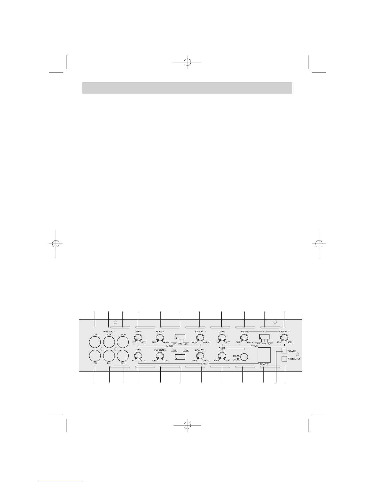
2.1 FRONT PANEL CONNECTIONS & CONTROLS
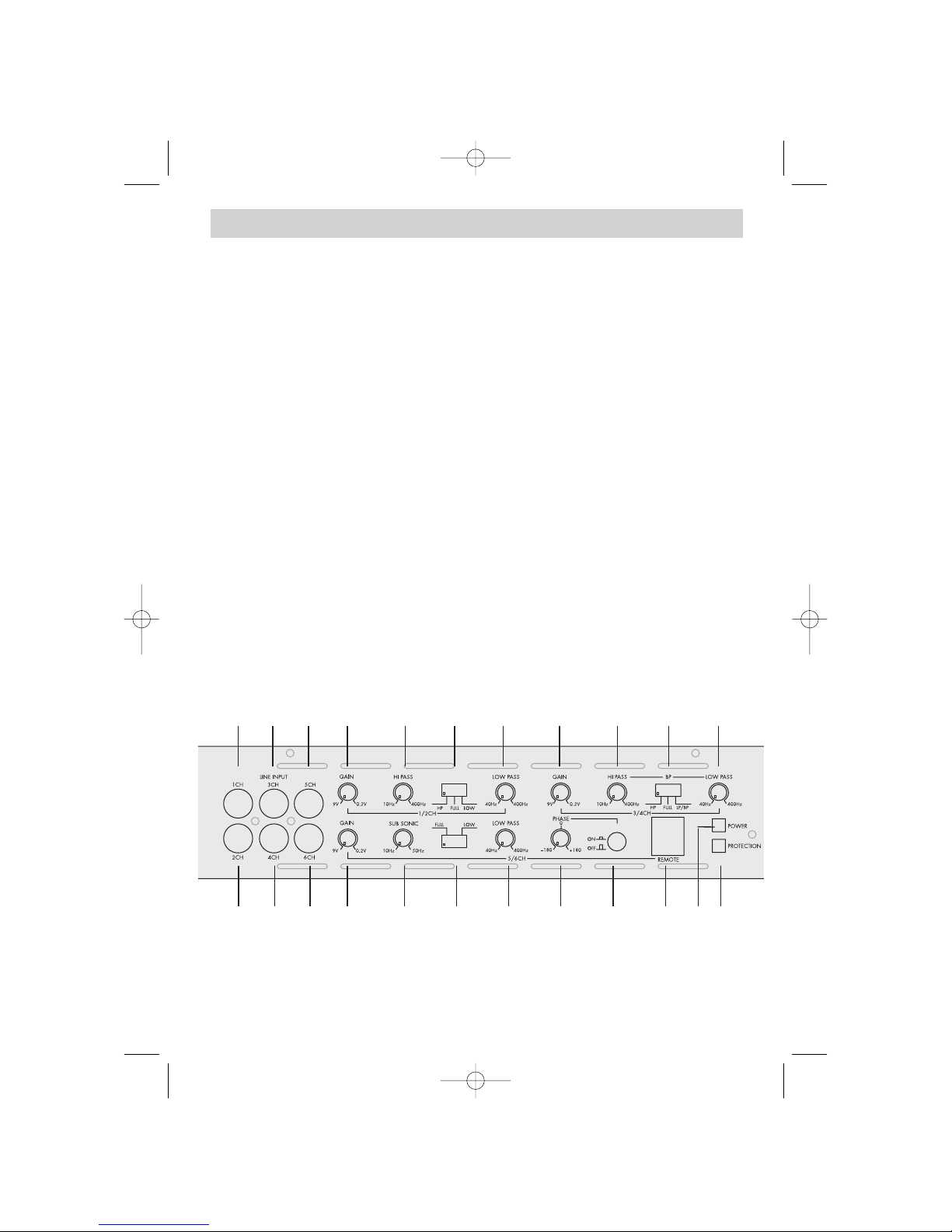
1a/1b RCA INPUTS 1/2-CH
Low-level stereo RCA signal input for connection with head-unit. See chapter 6.1
2a/2b RCA INPUTS 3/4-CH
Low-level stereo RCA signal input for connection with head-unit. See chapter 6.1
3a/3b RCA INPUTS 5/6CH
Low-level stereo RCA signal input for connection with head-unit. See chapter 6.1
4 INPUT GAIN CONTROL 1/2-CH
Input level control for 1/2-CH amplifier section - allowing to match the output voltage of the
head-unit's RCA line-outs to the amplifier input section. See chapter 7.6
5 HIGH PASS FREQUENCY CONTROL 1/2-CH
Control for the frequency adjustment of the 12dB/oct. high-pass filtering of the speakers
connected to 1/2-CH output terminals. See chapter 7.2
6 OPERATION MODE SWITCH 1/2-CH
Switch to select the operation mode of the active filter driving 1/2-CH section of the
amplifier. See chapter 7.1
7 LOW PASS FREQUENCY CONTROL 1/2-CH
Control for the frequency adjustment of the 12dB/oct. low-pass filtering of the speakers
connected to 1/2-CH output terminals. See chapter 7.4
8 INPUT GAIN CONTROL 3/4-CH
Input level control for 3/4-CH amplifier section - allowing to match the output voltage of the
head-unit's RCA line-outs to the amplifier input section. See chapter 7.6
9 HIGH PASS FREQUENCY CONTROL 3/4-CH
Control for the frequency adjustment of the 12dB/oct. high-pass filtering of the speakers
connected to 3/4-CH output terminals. See chapter 7.2 or 7.3
10 OPERATION MODE SWITCH 3/4-CH
Switch to select the operation mode of the active filter driving 3/4-CH section of the
amplifier. See chapter 7.1
11 LOW PASS FREQUENCY CONTROL 3/4-CH
Control for the frequency adjustment of the 12dB/oct. low-pass filtering of the speakers
connected to 3/4-CH output terminals. See chapter 7.3 or 7.5
12 INPUT GAIN CONTROL 5/6-CH
Input level control for 5/6-CH amplifier section - allowing to match the output voltage of the
head-unit's RCA line-outs to the amplifier input section. See chapter 7.6
13 SUBSONIC FREQUENCY CONTROL 5/6-CH
Control for the subsonic 12dB/oct. high-pass frequency adjustment of the speakers
connected to 5/6-CH output terminals. See chapter 7.5
14 OPERATION MODE SWITCH
Switch to select the operation mode of the active filter driving 5/6-CH section of the
amplifier. See chapter 7.1
EA 6-CH Manual 12.03.2002 13:31 Uhr Seite 6
Page 7
7
2. CONNECTIONS & CONTROLS
15 LOW PASS FREQUENCY CONTROL 5/6-CH
Control for the frequency adjustment of the 12dB/oct. low-pass filtering of the speakers
connected to 5/6-CH output terminals. See chapter 7.5
16 PHASE SHIFT CONTROL
Control for the relative phase adjustment of the speaker(s) connected to 5/6-CH amplifier
output terminals. See chapter 7.7
17 PHASE SHIFT ON/OFF CONTROL
ON/OFF switch to activate or deactivate the phase shift function of the speaker(s)
connected to 5/6-CH amplifier output terminals. See chapter 7.7
18 REMOTE LOW PASS LEVEL INPUT
Telephone jack input socket for connection with the dash-mounted low-pass level remote unit.
The remote low pass level control is for channels 5/6-CH, and it is only active when the
operation mode switch is set to lowpass! See chapter 6.1
19 POWER LED
Green "operation" LED, signaling correct operation of the amplifier. See chapter 7.5
20 PROTECTION LED
Red "protection" LED, signaling faulty speaker connections or general malfunction of the
amplifier. See chapter 7.5
1a 2a 3a 4 5 6 7 8 9 10 11
123b 132b1b 14 15 16 17 18 19 20
EA 6-CH Manual 12.03.2002 13:31 Uhr Seite 7
Page 8
8
2. CONNECTIONS & CONTROLS
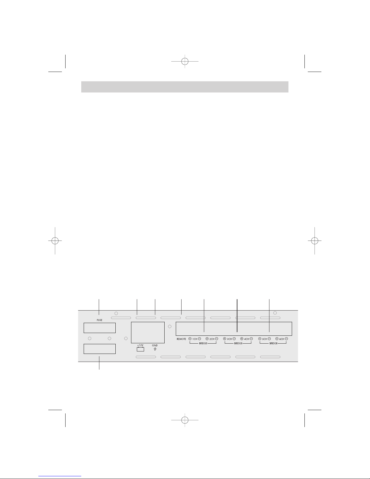
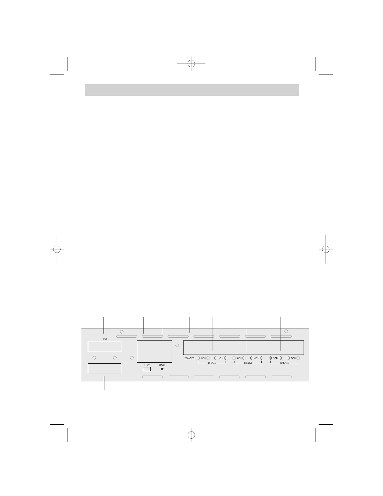
21a 22
21b
23 24 25 26 27
2.2 REAR PANEL CONNECTIONS & CONTROLS
21a/ FUSES
21b
Two 80A Maxi fuses for protection of the amplifier electronics against overload or
wrong operation / manipulation. See chapter 8.0
22 POWER INPUT TERMINAL "+ 12 V"
Terminal to connect the amplifier to the positive +12V pole of the car battery.
See chapter 6.3
23 POWER INPUT TERMINAL "GND"
Terminal to connect the amplifier to the negative or ground pole of the car battery.
See chapter 6.3
24 REMOTE INPUT TERMINAL
Terminal to connect the amplifier to the automatic (remote) turn-on / turn-off lead of the
head unit. See chapter 6.1
25 SPEAKER OUTPUT TERMINALS 1/2-CH
Output terminal to connect the speakers to the 1/2-CH channels of the amplifier.
See chapter 6.2
26 SPEAKER OUTPUT TERMINALS 3/4-CH
Output terminal to connect the speakers to the 3/4-CH channels of the amplifier.
See chapter 6.2
27 SPEAKER OUTPUT TERMINALS 5/6-CH
Output terminal to connect the speakers to the 5/6-CH channels of the amplifier.
See chapter 6.2
EA 6-CH Manual 12.03.2002 13:32 Uhr Seite 8
Page 9

9
3. INSTALLATION PLANNING
3.1 PLAN OF ATTACK
Before you proceed to install the EA 4100-500 6-channel amplifier, it is recommended to map out the
complete audio system and the respective wiring required. Consider all additional electrical requirements and accessories, such as power cables, interconnect cables and power ring terminals/battery
clamps needed, to connect this amplifier. Consider i.e. a safe mounting, sufficient ventilation, convenient accessibility of the fuses and the side panel controls, as well as availability of space for all peripheral system equipment. Your work will be considerably simplified, if you have a clear idea or 'plan
of attack'.
Please note that - because of possible interference problems with the existing car electrics and electronics - especially the routing of the signal cables and the chassis ground connection will have a profound impact on a trouble-free operation of the amplifier.
If you have no or only little experience with complex car audio installations, we
strongly recommend you to consult your nearest authorized EMPHASER
dealer/installer.
3.2 MOUNTING LOCATION
The mounting location should be carefully selected and in the interest of passive driver and passenger
safety, the amplifier must be securely mounted. Check the suitability of your preferred amplifier location carefully, before you start any installation attempts. Any mounting position - preferably in the trunk
compartment - that allows sufficient cooling is okay. A good air stream across the fins of the amplifier's heatsink will provide adequate ventilation and therefore improve cooling and full output capability dramatically. The air in- and outlets in the side-panels must not be covered, since they are part
of the amplifier’s internal heat management by a temperature controlled fan!
Make sure there is no wiring harness, fuel tank etc. behind or below the mounting surface, that may
be damaged by the drilling of the holes for the amplifier mounting screws. After installation, there
should be a clearance of at least 5cm on all sides including the top of the amplifier heatsink. Make
sure the unit is not exposed to direct sunlight, humidity, water, oil or spill of other fluids that may enter
the amplifier.
EA 6-CH Manual 12.03.2002 13:32 Uhr Seite 9
Page 10

10
4. GENERAL INFO ABOUT WIRE CROSS SECTIONS AND
CABLE QUALITY
4.1 MAIN POWER CABLE CROSS SECTION
EMPHASER recommends a minimum power cable cross-section of 35mm2concerning the main and the ground power supply cables for the EA4100-500. In case
of very low impedance loads, such as 1 ohms stereo or 2 ohms bridged, it is suggested to operate this amplifier with 50mm
2
main power cables.
These recommendations guarantee trouble-free operation of the EA4100-500 amplifier, giving you full
and trouble-free power output. Using main power cables with cross sections smaller than 35mm2will
result in unnecessary over-heating of the amplifier circuitry, distortion at high volume levels and it may
even cause the thermal protection circuitry to trigger, and shut-down the amplifier!
4.2 RCA INTERCONNECTS
It is obvious that for best performance of your EA4100-500 amplifier, you should stick to high quality RCA interconnect cables. Use twisted pair or triple shielded types only. Keep in mind, the RCA interconnects should always be kept far away from any potential sources of electrical interference e.g. electronic vehicle management systems (engine computers, relays etc.) fuel pumps, wiring harnesses etc.!
4.2 LOUDSPEAKER CABLES
Use good quality speaker wires of minimum 2.5mm2, up to 4.0mm2cross-section, depending on the
necessary total length!
4.3 MINIMUM SPEAKER IMPEDANCES
The heat dissipation capacity of this 6-channel amplifier has been designed to cope with low impedance loads, such as 1 ohms for stereo speaker setups or 2 ohms in bridged mode operation.
However, EMPHASER laboratories recommend to stay above 2 ohms in bridged operation mode, to
guarantee a good damping factor to precisely control the connected speaker(s).
5. AMPLIFIER MOUNTING
Attention! For your own safety, disconnect the positive battery terminal (+12V) or
remove the main fuse in the positive power cable near the car battery, before you
start any wiring work!
Once the location where the amplifier will be mounted is defined, use the unit as a template for the
marking of the mounting holes with pencil or felt-tip marker. The mounting holes should be pilot-drilled, using a 2,5mm or 3mm drill bit. For the actual mounting, the supplied rubber washers have to be
pressed into the mounting holes before attaching the amp to the panel with the supplied mounting
screws.
Important! There must not be a direct contact of the amplifier heatsink, bottom
panel or any other metal part of the amplifier to the vehicle! Electrical groundloops can easily result in audible hum! Now secure the amplifier in its position by
tightening the screws evenly and re-check proper fit after completion.
EA 6-CH Manual 12.03.2002 13:32 Uhr Seite 10
Page 11

11
6. CABLE ROUTING
6.1 RCA INTERCONNECTS AND REMOTE WIRING
Carefully run the audio signal interconnects, the remote lead and the cable of the remote low pass level
boost unit from the head-unit or dashboard to the amplifier. As mentioned before, the audio signal
cables should be routed completely separate from the power cables. Connect the remote (turn on/turn
off) lead to the respective input terminal of the amplifier and to the remote output of your head-unit.
Now you can connect the RCA interconnects to the respective outputs of your head-unit and to the
inputs of the amplifier. Pay attention to connect the stereo interconnects correspondingly, left is 1-CH,
right is always 2-CH (uneven numbers are left, even numbers are right).
Mount the remote low pass level boost unit in a convenient position under or besides the dashboard
and connect the respective cable between the remote device and the amplifier. If your head-unit features a variable sub-level output, you can omit the mounting of this additional low pass level remote
control device ("it's up to you to choose, which of both options will serve you better"!).
6.2 CONNECTION OF LOUDSPEAKER WIRES
Once the speaker cables have been routed, turn loose the Allen screws of the speaker terminal binding posts and - after inserting the stripped speaker cables - re-tighten the screws. When baring wires
for connection, remove approximately 6-8mm of the insulation and after axially twisting the wires,
insert the bare ends into the corresponding speaker terminal output on the amplifier. Maintain correct
polarity ("+" to "+"; "-" to "-").
6.3 MAIN POWER CABLE ROUTING
Run the positive main power cable ("+12 V") directly from the positive terminal of the car battery to
the amplifier. Make sure to use an appropriate battery clamp, that accepts big gauge cable diameters. Make sure to clean both battery poles from surface corrosion, before connecting the battery
clamps. For protection of your car audio system against electrical fire hazards, resulting from a shortcircuit of the main power cable to chassis ground an ANL fuse holder must be inserted wit-
hin the first 30cm of the positive main power cable. The applicable fuse value must be
matched to the limitations of your main power cable AND the current draw of the amplifier - therefore choose a fuse value of either 150 or 200A. Always keep in mind, that the EA4100-500 amplifier
is capable of 160A max. current drain!
Now you attach the ground cable to the amplifier. In most cases it will be best to keep the
ground cable ("-12V") as short as possible, i.e. to find a chassis contact very close to the amplifier.
The ground power cable must have the same cross-section as the positive power cable. It is recommended to use a corrosion-resistant gold-plated ground clamp to obtain the lowest possible contact
resistance for the chassis ground connection. The contact surface point on the car chassis must be solid
and clean, i.e. free from rust or paint!
Tighten both power input terminals of the amplifier, and double check for perfect fit of both main cable
leads!
EA 6-CH Manual 12.03.2002 13:32 Uhr Seite 11
Page 12
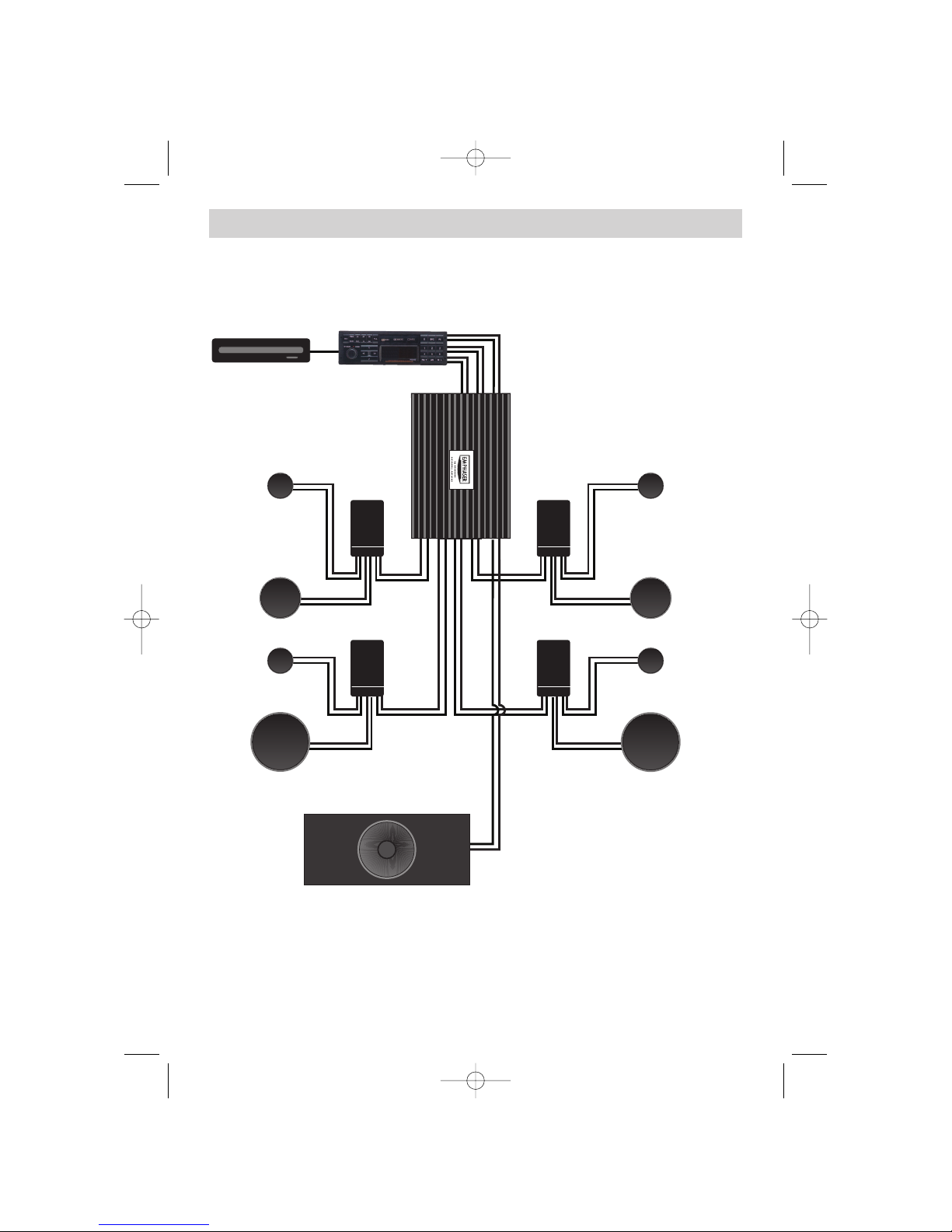
12
6.4 TWIN-SATELLITE / SUBWOOFER SYSTEM
CD-CHANGER HEAD-UNIT
PRE-OUT FRONT, REAR & SUB
BASS-MIDRANGE
X-OVER X-OVER
TWEETER
X-OVER
X-OVER
BASS-MIDRANGE
TWEETER
BASS-MIDRANGE
TWEETER
BASS-MIDRANGE
TWEETER
CHANNEL 1-CH
CHANNEL 3-CH
CHANNEL 2-CH
CHANNEL 4-CH
CHANNEL
5/6-CH
TRUNKBOX SUBWOOFER
EA 6-CH Manual 12.03.2002 13:32 Uhr Seite 12
Page 13
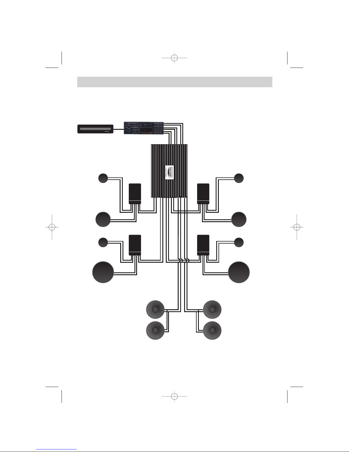
13
6.4 TWIN-SATELLITE / KICKBASS SYSTEM
CD-CHANGER HEAD-UNIT
PRE-OUT FRONT, REAR & SUB
BASS-MIDRANGE
X-OVER X-OVER
TWEETER
X-OVER
X-OVER
BASS-MIDRANGE
TWEETER
BASS-MIDRANGE
TWEETER
BASS-MIDRANGE
TWEETER
CHANNEL 1-CH
CHANNEL 3-CH
CHANNEL 2-CH
CHANNEL 4-CH
KICKBASS
STEREO
CHANNEL 5
CHANNEL 6
EA 6-CH Manual 12.03.2002 13:32 Uhr Seite 13
Page 14
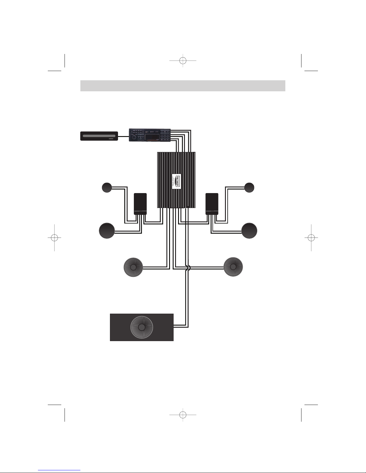
14
6.4 FRONT SATELLITE / KICKBASS/ SUBWOOFER SYSTEM
CD-CHANGER HEAD-UNIT
PRE-OUT FRONT, REAR & SUB
BASS-MIDRANGE
X-OVER X-OVER
TWEETER
BASS-MIDRANGE
TWEETER
CHANNEL 1-CH
CHANNEL 3-CH
CHANNEL 2-CH
CHANNEL 4-CH
KICKBASS
STEREO
CHANNEL
5/6-CH
TRUNKBOX SUBWOOFER
KICKBASS
STEREO
EA 6-CH Manual 12.03.2002 13:32 Uhr Seite 14
Page 15

15
7. ADJUSTMENT OF THE CONTROL FUNCTIONS
7.1 SELECTING THE OPERATION MODE FOR 1/2-CH & 3/4-CH CHANNELS
Before you power up your amplifier, you must select and set an appropriate operation mode first,
depending on the speaker systems connected to the "satellite channel pairs" 1/2-CH and 3/4-CH.
The EMPHASER EA4100-500 is multi-channel amplifier with integrated active crossovers and thus,
offers different amplification modes which can be set by the operation mode slide switches. Three of
these switches can be found on your amplifier. These switches enable you to configure each stereo
channel pair to work in either in fullrange, highpass, lowpass or even bandpass mode. Therefore you
must now select the appropriate operation mode for each channel pair: For example select HIGHPASS,
if the speaker system is a component-, coaxial- or triaxial- type, respectively LOWPASS / BANDPASS
in case of a kickbass system or a subwoofer. If you own a head-unit, that spots an integrated DSP controlled active crossover, it is recommended to use the DSP based crossovers - in this case you need to
set all three operation mode slide switches to FULL(range)!
In all other cases, i.e. when your head-unit does NOT feature integrated DSP controlled active filters
or for some reasons you don't want to use them, you MUST set the OPERATION MODE of each channel pair to the corresponding HP, LP or BP setting, that correlates to the function of the connected
speaker pair! Otherwise, your speaker system might be damaged!
Selecting the appropriate operating mode for each channel pair makes sure, that the speakers connected to the amplifier outputs will only receive filtered signals, so the speakers will only have to work
in the frequency bands they can reproduce best.
7.2 SELECTING A CROSSOVER FREQUENCY POINT FOR SATELLITE
SPEAKERS
The channel pairs 1/2-CH and 3/4-CH are mostly used and intended to drive satellite speakers.
Therefore these channels feature a highpass ("HP") crossover. For satellite speakers, you must select
the position "HP" on the OPERATION MODE switch. "HP" operation mode will take away unnecessary mechanical and electrical 'strain' from coaxial or component speaker systems, as they cannot reproduce strong and low bass signals anyway. Depending on the actual cone surface, voice-coil diameter
and the rated power handling of the installed 'satellite' speakers, it is recommended to set the highpass cross-over frequency point between 50 and 150Hz, using the "HI PASS" frequency control.
Note, that the appropriate setting should always be determined by ear! The two most important factors for this individual adjustment will be the reproduction of the mid-bass frequencies and the required safe power-handling capacity (cone excursion!) of the satellites, so the highpass crossover frequency point is always a compromise setting.
Front Door Satellite Speaker System ("HP" enabled, 1/2-CH) HP Cross-Over Frequency
13 cm 2-way Component System 80 - 110Hz
16 cm 2- or 3-way Component System 50 - 80Hz
Rear Satellite Speaker System ("HP" enabled, 3/4-CH) HP Cross-Over Frequency
13 cm 2-way Coaxial or Component System 100 - 120Hz
16 cm 2-way Coaxial or Component System 100 - 120Hz
6x9" or 7x10" Triaxial Speaker System 100 - 120Hz
EA 6-CH Manual 12.03.2002 13:32 Uhr Seite 15
Page 16

16
7. ADJUSTMENT OF THE CONTROL FUNCTIONS
7.3 SELECTING A CROSSOVER FREQUENCY POINT FOR THE KICKBASS
SPEAKERS
For a front door installed 16cm kickbass system - consisting of one up to four 16cm kickbass speaker
units per door - the OPERATION MODE switch must be set to LP/BP. This mostly concerns channel pair
3/4-CH, while channel pair 1/2-CH will be used to drive the satellite system mounted in the front
doors. So the OPERATION MODE switch of 1/2-CH section must be set to HP, if this is the case.
The cross-over frequency point settings should be chosen according to the recommendations below:
Kickbass Speakers System ("LP/BP" enabled, 3/4-CH) HI PASS LOW PASS
1 x 16cm kickwoofer unit per front door 100 - 110Hz 200 - 300Hz
2 x 16cm kickwoofer units per front door 90 - 100Hz 200 - 300Hz
3 x 16cm kickwoofer units per front door 80 - 100Hz 200 - 300Hz
7.4 LOWPASS CROSSOVER FREQUENCY ADJUSTMENTS FOR THE SUBWOOFER
The EA 4100-500 enables the user to use all three channel pairs in lowpass (subwoofer) mode operation, although this function is mostly centered around the channels 5/6-CH, which offer the highest
power output of the six channels. Furthermore, the 5/6-CH channels feature a subsonic filter and a
phase shift control.
Select the switch position "LOW" on the OPERATION MODE CONTROL switch, of the 5/6-CH control section, in order to let this channel pair operate in low-pass mode.
Before you can attempt to find the sonically best lowpass crossover frequency point, you must set the
subsonic highpass filter control to its lowest position (10Hz).
Close the electrical circuit by inserting the main fuse. Now switch on your head unit. The green OPERATING LED of the EA4100-500 power amplifier should light-up. If the LED lights up red, your installation is faulty! Turn off the head-unit and carefully re-check previous installation steps!
The LOW PASS cut-off frequency point setting depends on the amplitude response and the frequency
extension of the installed subwoofer system. As a rule of thumb, settings in a range between 60 to 90
Hz will render best sonic results. This setting is mostly a matter of taste, and should therefore be 'played by ear'. Turn up the input gain control knob of CH5/6 to "noon" position, and turn on your head
unit. Now set the desired lowpass frequency by adjusting the LOW PASS frequency control knob. In
general, setting the lowpass cross-over frequency too low, will result in a weak and muddy sounding
bass, while setting this crossover frequency too high will result in a 'booming' bass sound and reduced low end extension.
EA 6-CH Manual 12.03.2002 13:32 Uhr Seite 16
Page 17

17
7. ADJUSTMENT OF THE CONTROL FUNCTIONS
7.5 SUBSONIC CROSSOVER FREQUENCY ADJUSTMENT FOR THE SUBWOOFER
Ideally, the subsonic highpass frequency should be set according to the size and function principle of
the subwoofer system, installed in this system configuration. The higher the subsonic crossover frequency is set, the higher the mechanical power handling of the subwoofer system will be. The tradeoff is reduced low end extension, since nothing comes free! So turn up the volume of your head unit
and set the subsonic (highpass) frequency to fit your own taste and requirements, in a way you reach
a good compromise of power handling and convincing low end reproduction. There are no specific
recommendations…
7.6 ADJUSTMENT OF THE INPUT GAIN CONTROLS
To reach a maximum in dynamic response from each individual head-unit/amplifier/speaker combination, it is important to set the respective input sensitivity controls ("GAIN") of all channel pairs correctly.
Before you start, you MUST set all tone controls (Bass, Mid, Treble, Loudness etc.) and the fader
on the head unit to their neutral or center positions.
Now turn all three input gain controls (CH1/2, CH3/4 and CH5/6) on the amplifier anti-clockwise to
their minimum positions. The REMOTE LOW PASS LEVEL BOOST of the remote unit shall be set to its
minimum position too.
SUBWOOFER CHANNELS
Set the volume control of your head-unit to approximately 3/4 of full volume, while playing a dynamic track of music. Slowly increase the input gain control of channels 5/6-CH by turning the control
knob clockwise, until you can just about hear distorted sounds from your subwoofer. Reduce the main
volume level on your head-unit to a medium listening level.
CHANNELS 1/2-CH
Slowly increase the input gain control of channels1/2-CH by turning the knob clockwise until you
reach a good tonal balance, with a slight emphasis of the bass range. Aim at a full bodied bass
response.
REAR CHANNELS / FRONT KICKBASS CHANNELS
Now slowly turn up the input gain control of the channel pair 3/4-CH, until you have either reached
a good balance between the front and rear satellites, or the front satellites and the kickbass woofer
units. In case of a front door installed kickbass system, a slight emphasis on the kickbass range is
recommended, as this will be compensated later by normal driving noises.
FINE TUNING OF ALL CROSSOVER FREQUNCY POINT SETTINGS
Finally you can attempt to fine-tune the HP, BP and LP cross-over frequencies on your amplifier, to
reach the maximum tonal balance and channel integration of all loudspeakers connected to your
EA4100-500.
EA 6-CH Manual 12.03.2002 13:32 Uhr Seite 17
Page 18

18
7. ADJUSTMENT OF THE CONTROL FUNCTIONS
7.7 PHASE SHIFT CONTROL
The phase shift control - to be activated by the ON/OFF switch on channel section 5/6-CH - provides
you with a simple "tool" to match the front door installed satellite system with the subwoofer playing
in the trunk compartment of your car. The phase shift control is used to achieve a good match of the
phase (time) relation between satellite and subwoofer system.
Since the satellite speaker system and the subwoofer are playing in locations separated by at least
2.5m, there is always a time difference between these two speaker systems, that usually cross over between 60 to 120Hz. But a difference in phase bigger than 90° will cause a partial cancellation of the
frequencies that are radiated at the specific crossover point. Two effects derive from this fact: 1. the
sound reproduction is not as tight as it can be, and 2. the subwoofer can easily be localized to play
in the trunk of your car.
There is no rule of thumb, so this setting must entirely matched by ear! The assistance of somebody
adjusting the phase shift in the back of your car, while you monitor the change of sound - complicates this matter. At least, you need a buddy to help you and an optimised phase match between satellite speakers and the subwoofer is well worth the efforts!
EA 6-CH Manual 12.03.2002 13:32 Uhr Seite 18
Page 19
19
BEDIENUNGS- UND INSTALLATIONSANLEITUNG
Herzlichen Glückwunsch!
Wir danken Ihnen, dass Sie sich zum Kauf der EMPHASER EA4100-500 6-Kanalendstufe entschieden
haben. Sie besitzen nun ein sehr hochwertiges Produkt, das mit einem kompromisslosen technischen
Aufbau aufwartet. Die EA4100-500 setzt Masstäbe bezüglich Leistungsabgabe, Klangqualität und
Bedienungsfreundlichkeit.
Damit Sie die Wiedergabequalität und die Leistungsfähigkeit Ihres Verstärkers voll ausschöpfen können, möchten wir Sie bitten, sich eingehend mit den Möglichkeiten und technischen Features dieses
Verstärkers vertraut zu machen. Lesen Sie deshalb die nachfolgenden Abschnitte sorgfältig durch und
bewahren Sie diese Bedienungsanleitung für allfällige, vielleicht später auftauchende Fragen auf.
WICHTIGE INFO:
Wenn Sie den Einbau Ihres Car-HiFi Systems selbst vornehmen, lassen Sie
dieses von Ihrem Händler auf fachgerechte Installation überprüfen. Damit
sichern Sie sich Ihre Garantieleistungen und stellen sicher, dass die Anlage
ihre volle Klangqualität und Leistungsfähigkeit erreicht.
Längere Einwirkung von sehr hohen Schallpegeln kann zu Gehörschäden
führen. Seien Sie daher bitte vorsichtig, Hörschäden sind irreversibel!
EA 6-CH Manual 12.03.2002 13:32 Uhr Seite 19
Page 20

20
1. TECHNISCHER AUFBAU / MERKMALE
■ 6-KANAL VERSTÄRKER: Die EA4100-500 dient zur Realisierung eines einbaufreundlichen
klangstarken 5/6-kanaligen Subwoofer/Satelliten Systems, z.B. bestehend aus zwei Sets
Komponentenlautsprecher (im Front und Heckbereich) und einem Subwoofer (im Kofferraum)
■ SUBWOOFERPEGELREGELUNG ÜBER EXTERNE KABELFERNBEDIENUNG: Das im Fond
des Fahrzeuges frei montierbare kleine Bedienteil ermöglicht die Fernbedienung der Lautstärke des
Subwoofers, bzw. der Kanäle 5 und 6 im Tiefpass-Betrieb
■ Zwei einzelne vollständig getrennte MOS-FET Netzteile: Die EA4100-500 ist mit zwei
separaten Netzteilen bestückt, dies verhindert eine gegenseitige Beeinflussung der einzelnen
Verstärker-Kanäle für die Satelliten und den Subwoofer
■ 1 OHM STABILITÄT: Dieser 6-Kanal Amp lässt sich auf jedem Kanal mit Lastimpedanzen bis auf
1 Ohm belasten. Das Design der Ausgangstufe ist ausserdem auf niedrigen Innenwiderstand getrimmt,
alle Kanäle haben durch den resultierenden hohen Dämpfungsfaktor die angeschlossenen
Lautsprecher voll "im Griff"
■ INTEGRIERTE ELEKTRONISCHE FREQUENZWEICHE: Die drei Kanalpaare werden über drei
einzelne, vollkommen unabhängige elektronische Frequenzweichen mit einer Flankensteilheit von 12
dB/Okt. angesteuert. Es lassen sich Hochpassfilter, Tiefpassfilter und Bandpassfilter wählen, oder der
jeweilige Weichenzweig kann vollständig umgangen werden
■ KOMPROMISSLOSER AUFBAU UND KONSTRUKTION: Durch die ausschliessliche
Ver wendung von hochwertigsten Materialien in der Fertigung, ist die Betriebssicherheit besonders
hoch. Zum Einsatz kommen z.B. doppelseitig kaschierte Glasfaser-Epoxydharzplatinen, hochstromfähige Transistoren etc. Weiterhin verfügt die EA4100-500 über 35mm
2
Power-Input Terminals, für vol-
len unlimitierten Stromfluss sorgen
■ INTELLIGENTE SCHUTZSCHALTUNG: Die integrierte Schutzschaltung erkennt Kurzschlüsse an
den Lautsprecherausgängen, Gleichspannung im Ausgangssignal und überhöhte Betriebstemperatur.
Fehlerhafte Betriebszustände führen zum sofortigen Abschalten des Gerätes
■ POWER / PROTECT LED'S: Am Input-Side Panel befinden sich zwei LED's, die grün leuchtende
Status LED, welche normale Operation des Verstärkers anzeigt, als auch eine weitere rote LED, die bei
Problemen wie Kurzschlüssen, elektrischer / thermische Überlastung und Gleichspannung an den
Anschlussklemmen rot aufleuchtet
■ GROSSER REGELBEREICH DER EINGANGSEMPFINDLICHKEIT: Alle Line Level
Eingangspaare akzeptieren Vorverstärker-Signale von 200mV bis 9V. Dies garantiert, dass diese
Endstufe mit allen am Markt erhältlichen Steuergeräten kombiniert werden kann
■ EXTERNE SICHERUNGEN: Für die Absicherung des internen Verstärker-Netzteiles befinden sich
auf der Power-Eingansseite zwei entsprechende 80A Maxi-Sicherungen. Diese lassen sich im
Bedarfsfalle schnell austauschen
■ INTERNER LÜFTER: Diese Endstufe ist intern mit einem temperaturgesteuerten Lüfter ausgestattet.
Er sorgt auch bei Vollastbetrieb für ein sehr effektives Hitzemanagement
EA 6-CH Manual 12.03.2002 13:32 Uhr Seite 20
Page 21

21
2. ANSCHLÜSSE & BEDIENUNGSELEMENTE
2.1. EINGÄNGE & FUNKTIONEN AM FRONT PANEL
1a/1b CINCH INPUTS 1/2-CH
Cinch Eingangsbuchsen 1/2-CH für den Anschluss der Cinch Ausgänge des Steuergerätes
siehe Abschnitt 6.1
2a/2b CINCH INPUTS 3/4-CH
Cinch Eingangsbuchsen 1/2-CH für den Anschluss der Cinch Ausgänge des Steuergerätes
siehe Abschnitt 6.1
3a/3b CINCH INPUTS 5/6-CH
Cinch Eingangsbuchsen 1/2-CH für den Anschluss der Cinch Ausgänge des Steuergerätes,
siehe Abschnitt 6.1
4 REGLER EINGANGSEMPFINDLICHKEIT 1/2-CH
Eingangsempfindlichkeitsregler der Kanäle 1/2-CH, für die Anpassung an die
Ausgangsspannung des Steuergerätes, siehe Abschnitt 7.7
5 REGLER HOCHPASS TRENNFREQUENZ 1/2-CH
Regler zum Einstellen der Hochpass-Trennfrequenz an der integrierten
elektronischen Frequenzweiche der Kanäle 1/2-CH, siehe Abschnitt 7.2
6 SCHALTER FÜR OPERATION MODE DER KANÄLE 1/2
Schiebeschalter für die Festelegung der Arbeitsweise der integrierten elektronischen
Frequenzweiche der Kanäle 1/2-CH, siehe Abschnitt 7.1
7 REGLER TIEFPASS TRENNFREQUENZ DER KANÄLE 1/2-CH
Regler zum Einstellen der Tiefpass-Trennfrequenz an der integrierten
elektronischen Frequenzweiche der Kanäle 1/2-CH, siehe Abschnitt 7.4
8 REGLER EINGANGSEMPFINDLICHKEIT DER KANÄLE 3/4-CH
Eingangsempfindlichkeitsregler der Kanäle 3/4-CH, für die Anpassung an die
Ausgangsspannung des Steuergerätes, siehe Abschnitt 7.7
9 REGLER HOCHPASS TRENNFREQUENZ 3/4-CH
Regler zum Einstellen der Hochpass-Trennfrequenz an der integrierten
elektronischen Frequenzweiche der Kanäle 3/4-CH, siehe Abschnitt 7.2
10 SCHALTER FÜR OPERATION MODE DER KANÄLE 3/4-CH
Schiebeschalter für die Festelegung der Arbeitsweise der integrierten elektronischen
Frequenzweiche der Kanäle 3/4-CH, siehe Abschnitt 7.1
11 REGLER TIEFPASS TRENNFREQUENZ DER KANÄLE 3/4-CH
Regler zum Einstellen der Tiefpass-Trennfrequenz an der integrierten
elektronischen Frequenzweiche der Kanäle 3/4-CH, siehe Abschnitt 7.4
12 REGLER EINGANGSEMPFINDLICHKEIT DER KANÄLE 5/6-CH
Eingangsempfindlichkeitsregler der Kanäle 5/6-CH, für die Anpassung an die
Ausgangsspannung des Steuergerätes, siehe Abschnitt 7.7
EA 6-CH Manual 12.03.2002 13:32 Uhr Seite 21
Page 22
22
2. ANSCHLÜSSE & BEDIENUNGSELEMENTE
13 REGLER SUBSONIC TRENNFREQUENZ DER KANÄLE 5/6-CH
Regler zum Einstellen der Subsonic Hochpass-Trennfrequenz an der integrierten
elektronischen Frequenzweiche der Kanäle 5/6-CH, siehe Abschnitt 7.6
14 SCHALTER FÜR OPERATION MODE DER KANÄLE 5/6-CH
Schiebeschalter für die Festelegung der Arbeitsweise der integrierten elektronischen
Frequenzweiche der Kanäle 5/6-CH, siehe Abschnitt 7.1
15 REGLER TIEFPASS TRENNFREQUENZ DER KANÄLE 5/6-CH
Regler zum Einstellen der Tiefpass-Trennfrequenz an der integrierten
elektronischen Frequenzweiche der Kanäle 3/4-CH, siehe Abschnitt 7.5
16 REGLER FÜR DIE PHASEN-EINSTELLUNG DER KANÄLE 5/6-CH
Regler zum Einstellen der elektrischen Ausgangsphasenlage an der integrierten
elektronischen Frequenzweiche der Kanäle 5/6-CH, siehe Abschnitt 7.8
17 SCHALTER ZUM EIN- ODER AUSSCHALTEN DER PHASEN-REGELUNG
Schiebeschalter zum aktivieren oder deaktivieren der Phase-Shift Funktion an der
integrierten elektronischen Frequenzweiche der Kanäle 5/6-CH, siehe Abschnitt 7.8
18 EINGANG FÜR DIE SEPARATE FERNBEDIENUNGSEINHEIT
Telefonbuchsen Eingang, zum Anschluss der Verbindungskabels der Fernbedienungseinheit
der Kanäle 5/6-CH, siehe Abschnitt 6.1
19 POWER LED
Grüne "Power" LED; signalisiert den normalen Betriebszustand der Endstufe im
eingeschalteten Zustand, siehe auch Abschnitt 7.5
20 PROTECTION LED
Rote "Protection" LED; signalisiert eine generelle Fehlfunktion der Endstufe, wie z.B.
Kurzschluss an den Lautsprecherausgängen, Überhitzung sowie Gleichspannung an den
LS-Ausgängen, siehe Abschnitt 7.5
1a 2a 3a 4 5 6 7 8 9 10 11
123b 132b1b 14 15 16 17 18 19 20
EA 6-CH Manual 12.03.2002 13:32 Uhr Seite 22
Page 23
23
2. ANSCHLÜSSE & BEDIENUNGSELEMENTE
2.2 EINGÄNGE & FUNKTIONEN AM REAR PANEL
21a/ FUSES
21b Zwei 80A Maxi-Sicherungen für die interne Absicherung des Verstärkers gegen Überlastung
und Fehlmanipulation. Verwenden Sie für diese Endstufe nur 80 Ampere Maxi-Sicherungen,
siehe Abschnitt 8.0
22 + 12V" POWER INPUT TERMINAL
35mm
2
Eingangsterminal für den Anschluss an den Pluspol der Fahrzeugbatterie, siehe
Abschnitt 6.3
23 "GND" POWER INPUT TERMINAL
35mm
2
Eingansterminal für den Anschluss an die Chassis-Masse des Kfz's, oder den
Minuspol der Fahrzeugbatterie, siehe Abschnitt 6.3
24 "REM" INPUT TERMINAL
Eingangsterminal für den Anschluss des Remote-Kabels über den Amp- oder AntennaRemote Ausgang des Steuergerätes, siehe Abschnitt 6.1
25 LAUTSPRECHER AUSGANGS-TERMINAL FÜR KANÄLE 1/2-CH
Lautsprecheranschlussterminal für den Anschluss von einem Paar stereo Lautsprecher, oder
einem Lautsprecher in Brückenmodus an die Kanäle 1/2-CH, siehe Abschnitt 6.2
26 LAUTSPRECHER AUSGANGS-TERMINAL FÜR KANÄLE 3/4-CH
Lautsprecheranschlussterminal für den Anschluss von einem Paar stereo Lautsprecher, oder
einem Lautsprecher in Brückenmodus an die Kanäle 3/4-CH, siehe Abschnitt 6.2
27 LAUTSPRECHER AUSGANGS-TERMINAL FÜR KANÄLE 5/6-CH
Lautsprecheranschlussterminal für den Anschluss von einem Paar stereo Lautsprecher, oder
einem Lautsprecher in Brückenmodus an die Kanäle 5/6-CH, siehe Abschnitt 6.2
21a 22
21b
23 24 25 26 27
EA 6-CH Manual 12.03.2002 13:32 Uhr Seite 23
Page 24

24
3. PLANUNG DER INSTALLATION
Bevor Sie mit der Montage der EA4100-500 beginnen, erstellen Sie am besten eine kurze Anschlussund Installationsskizze. Zu berücksichtigen gilt es dabei hauptsächlich die Kabelverläufe und den
Installationsort des Car-Amps. Bedenken Sie bitte alle für den Anschluss dieser Endstufe benötigten
Zubehör- und Peripherie Teile, wie z.B. Stromkabel, Cinchkabel, Batterieklemmen, etc.
Der Verstärker sollte - auch angesichts seiner Grösse und seines Gewichts - möglichst gut und sicher
montiert werden. Besondere Aufmerksamkeit verdient sicher die "korrekte" Plazierung des Verstärkers
(ausreichende Luftzufuhr!), die Endstufe sollte auf keinen Fall "unzugänglich verbaut" werden, denn
am Schluss erfolgen an den Side-Panels die unumgänglichen Einstellarbeiten.
Beachten Sie bitte, dass die Kabelführung sowie der Massepunkt einen entscheidenden Einfluss auf das
störungsfreie Funktionieren Ihrer Anlage hat.
Wenn Sie wenig, oder gar keine Erfahrung mit dem Einbau von komplexen Car
Audio Geräten haben, empfehlen wir Ihnen unbedingt den Einbau dieser
Komponente durch den autorisierten und geschulten Fachhandel!
3.1 MONTAGEORT
Der Verstärker muss im Interesse der passiven Sicherheit stabil befestigt werden. Prüfen Sie, ob die
gewählte Montagefläche eben und stabil genug zur sicheren Befestigung des schweren Verstärkers ist.
Als Montageort eignet sich z.B. ein Platz im Kofferraum oder an einem Seitenteil, bzw jeder andere
Ort, der eine saubere Installation ermöglicht.
Stellen Sie eine ausreichende Belüftung sicher (mindestens 5 cm Freiraum oberhalb der Endstufe und
seitlich der Side-Panels). Dies ist sehr wichtig, weil die EA4100-500 über einen internen Lüfter verfügt
und der Luftaustausch durch kleine Fenster in den Side-Panels vonstatten geht. Diese Lüftungsöffnungen
dürfen auf keinen Fall abgedeckt werden. Vermeiden Sie weiterhin Montageorte mit "unbekanntem
Hintergrund". Es könnten sich ein Benzintank, hydraulische Bremsleitungen, Kabelbäume etc. dahinter verbergen! Achten Sie auch auf einen trocken, gegen mechanische Einwirkungen geschützten
Installationsort, der auch nach der Endmontage noch für die Bedienung und Einstellung
(Trennfrequenz- und Eingangsempfindlichkeits- Regelung etc!) des Verstärkers gut zugänglich ist.
EA 6-CH Manual 12.03.2002 13:32 Uhr Seite 24
Page 25
25
4. INFO'S ZU DEN KABELQUERSCHNITTEN & QUALITÄT
4.1 STROMKABEL QUERSCHNITT
EMPHASER empfiehlt als Minimum Kabelquerschnitt (bei einer Länge von 5m) 35mm2für +12V und
Massekabel. Falls die Endstufe an sehr niederohmigen Lasten arbeiten muss, z.B. 1 Ohm pro Kanal
stereo, oder 2 Ohm im Brückenmodus, empfiehlt sich der Einsatz von 50mm
2
Stromkabel.
Diese Vorschläge garantieren eine problemlose Funktion der EA4100-500, sowie die volle
Leistungsabgabe ohne übermässige Erwärmung. Bei zu gering gewähltem Batteriekabelquerschnitt
kann es zu einer starken Erhitzung des Verstärkers kommen, auf Grunde dessen dann die
Thermosicherung anspricht.
4.2 CINCHKABEL
Für eine Endstufe dieser Klasse sollten sie nur beste Cinchkabel verwenden. Verwenden Sie nur dreifach abgeschirmte Kabel, oder noch besser sogenannte "Twisted Pair" Typen. Beachten Sie, dass speziell die Musiksignalführenden (Cinch-) Kabel soweit wie nur möglich von allen potentiellen "elektrischen Störsendern" wie Bordcomputer, Benzinpumpe, Black Boxes, etc. verlegt werden.
4.3 LAUTSPERCHER KABEL
Ver wenden Sie qualitativ gutes Lautsprecherkabel mit einem minimalen Querschnitt von 2.5mm2, bei
grösseren Längen machen Kabelquerschnitte bis 4.0mm
2
durchaus Sinn.
4.4 MINIMALE LASTIMPEDANZ DER LAUTSPRECHER
Die Wärmekapazität der Kühlrippen dieser Endstufe wurde für sehr niederohmige Lasten ausgelegt.
Unterstützend wirkt der innenliegende Lüfter, der im Normalfall das Überhitzen der EA4100-500 verhindert. Die Kühlkapazität ermöglicht den Betrieb von allen Kanälen stereo an 1 Ohm. Trotzdem empfehlen wir Ihnen, im Brückenmodus (betrifft meist Kanäle 5/6) nicht unter 2 Ohm Lastimpedanz zu
gehen, da sonst der gute Dämpfungsfaktor entsprechend reduziert wird und die Endstufe an Kontrolle
einbüsst.
5. MONTAGE DES VERSTÄRKERS
ACHTUNG! Entfernen Sie zu Ihrer eigenen Sicherheit erst das Pluskabel vom
Pluspol der Batterie!
Bei allen nachfolgend beschriebenen Installationsschritten muss der Stromkreis des Kraftfahrzeugs
unterbrochen sein! Erst nach Abschluss aller Installationsarbeiten wird über das Pluskabel der
Stromkreis wieder geschlossen.
Halten Sie den Verstärker an den gewünschten Ort und markieren Sie mit einem geeigneten Filzstift
die Bohrposition der Befestigungslöcher.
Mit der gebotenen Vorsicht bohren Sie nun die angezeichneten Löcher mit einem 2,5 oder 3 mm
Bohrer.
Drücken Sie die beigelegten Gummitüllen in die Befestigungslöcher Ihres Verstärkers!! Ein
Masseschluss des Verstärkergehäuses auf die Kfz-Masse muss unbedingt vermieden werden!
(Brummschleife!)
Legen Sie nun den Verstärker auf die vorgebohrten Löcher und schrauben Sie die EA4100-500 fest.
Ziehen Sie die Schrauben gleichmässig an und überprüfen Sie abschliessend den einwandfreien Sitz
des Verstärkers.
EA 6-CH Manual 12.03.2002 13:32 Uhr Seite 25
Page 26

26
6. VERKABELUNG / ELEKTRISCHER ANSCHLUSS
6.1 VERLEGEN VON CINCH- UND REMOTE KABELN
Verlegen Sie das oder die Cinchkabel, das Fernbedienungskabel für die Pegel-Regelung von Kanälen
5/6 und das Remote-Kabel vom Steuergerät zur Endstufe.
Diese Kabel sollten unbedingt räumlich getrennt von der Stromzuführung des Verstärkers eingezogen
werden. Schliessen Sie das Remote-Kabel an das mit "REM" bezeichnete Terminal an der Endstufe und
an das mit Antenna-Rem. oder Amplifier-Rem. bezeichnete Kabel Ihres Steuergerätes an.
Anschliessend stecken Sie die Cinchkabel in die Cincheingangsbuchsen des Verstärker ein. Beachten
Sie hierbei die Seitenkennung, d.h. 1-CH ist links, 2-CH ist rechts, etc!
Nun wird noch das Fernbedienungseinheit (Kanal 5/6) in Griffnähe angebracht und die Stecker des
Kabels in die Buchsen am Verstärker und am Bedien-Panel eingesteckt. Diese Pegelregelung des
Kanalpaares 5/6-CH über die Fernbedienungseinheit ist optional. Sollten Sie eine Regelung der
Kanäle 5/6-CH über die regelbaren SUB-Line-Outs des Steuergerät bevorzugen, können Sie das
Kabel und die Fernbedienungseinheit auch weglassen.
6.2 ANSCHLUSS DER LAUTSPRECHERKABEL
Schliessen Sie nun die Lautsprecher Kabel an. Für den Anschluss am Verstärker benötigen Sie einen
Inbusschlüssel und ein Messer oder eine Zange, für das Abisolieren der Kabel. Entfernen Sie ca. 6-8
mm der Isolierung des LS-Kabels und beachten Sie die richtige Polung der
Lautsprecherkabel am Terminal (Plus auf Plus, Minus auf Minus). Ziehen Sie die LSSchraublemmen satt an.
6.3 VERLEGEN UND ANSCHLUSS DER HAUPT-STROMKABEL
Verlegen Sie nun das Pluskabel direkt von der Batterie zum Verstärker. Wir empfehlen die Verwendung von massiven Batterieklemmen, wegen dem grossen
Kabelquerschnitt.
Innerhalb der ersten 30 cm nach dem Pluspolklemmenabgriff muss eine Hauptsicherung angebracht
werden (Absicherung des Pluskabels gegen Kurzschluss auf Fahrzeug-Masse und dadurch resultierendem Kabelbrand!)
Ver wenden Sie eine dem Stromkabelquerschnitt entsprechende ANL Metallstreifen-Sicherung (normalerweise entweder 150A oder gar 200A). Setzen Sie die Sicherung erst nach Abschluss aller
Installationsarbeiten in den Sicherungshalter ein.
Nun schliessen Sie dass Minuskabel am Verstärker an. Versuchen Sie dieses Kabel so kurz wie möglich zu halten. Es sollte denselben Querschnitt wie das Pluskabel besitzen. Verwenden Sie für den
Massepunktanschluss eine Masseklemme, und achten Sie auf eine perfekt gesäuberte blanke
Metalloberfläche im Fahrzeug (schlechte Massepunkte sind für über 90 % aller Fälle der auftretenden
Störungen verantwortlich). Ein schlechter Massepunkt bedeutet nicht nur erhöhte Störungsanfälligkeit
und unnötige Erhitzung der Endstufe, sondern auch reduzierte Ausgangsleistung.
Schliessen Sie nun den Stromkreis zum Verstärker durch das Einsetzen der ANL Hauptsicherung. Ihr
Autoverstärker sollte nun beim Einschalten des Steuergerätes durch aufleuchten der grünen Power-LED
die Betriebsbereitschaft anzeigen. Leuchtet die Protection-LED rot auf, ist Ihre Installation fehlerhaft.
Gehen Sie die Installationsanweisungen nochmals genau durch.
EA 6-CH Manual 12.03.2002 13:32 Uhr Seite 26
Page 27

27
7. EINSTELLUNGEN AN DER FREQUENZWEICHE
7.1 WAHL DES "OPERATING MODES" DER FREQUENZWEICHE
In Abhängigkeit der angeschlossenen Lautsprechersysteme müssen Sie nun für die jeweiligen
Kanalpaare die Arbeitsweise der integrierten elektronischen Frequenzweiche definieren, bzw. den
OPERATION MODE Schiebeschalter für alle drei Kanalpaare in die gewünschte Stellung bringen.
Jedes Kanalpaar kann unabhängig von den andern Paaren entweder in Hochpass, Tiefpass oder
Bandpass Betrieb arbeiten.
Die Hochpass / Tiefpassfunktion der integrierten Frequenzweichen teilt den eingesetzten
Lautsprechersystemen wie z.B. Subwoofer, Koax- oder Komponentensystemen nur den
Frequenzbereich zu, für welchen die Lautsprecher geeignet sind. Falls Sie am Kanalpaar 1/2-CH ein
Komponentensystem betreiben wollen, müssen Sie den Operation Mode Schalter auf "HP" (für
Hochpass) stellen. Für ein Kickbass-System wählen Sie Bandpass, etc.
Falls Ihr Steuergerät über eine DSP basierte Frequenzweiche verfügt, so können Sie sämtliche
Aktivweichen in dieser Endstufe umgehen, die Konfiguration der Frequenzweichen auf DSP Basis
erfolgt dann direkt am Steuergerät. Hierzu müssen alle drei Operation Mode Schalter an der Endstufe
auf "FULL" gestellt werden. Wählen Sie also entsprechend entweder die DSP basierte Weiche an Ihrem
Steuergerät (falls vorhanden), oder die Weichenfunktionen an der Endstufe! Ein Betrieb von Kompooder Koaxialsystemen ohne (Hochpass)Weiche kann die angeschlossenen Lautsprecher zerstören!
7.2 WAHL DER TRENNFREQUENZ FÜR DIE SATELLITENSYSTEME
Mit der Einstellung der Trennfrequenz des Hochpasses (HP) soll eine elektrische und mechanische
Entlastung der verwendeten Koax oder Komponentensysteme erfolgen. Je nach der vorhandenen
Membranfläche und Nennbelastbarkeit der verwendeten (Satelliten)-Systeme empfiehlt sich eine
Trennfrequenz im Bereich zwischen 50 bis 150Hz. Diese Einstellung kann über den "HI-PASS" Regler
vorgenommen werden.
Die Einstellung der Hochpass Trennfrequenz - sie stellt immer einen Kompromiss dar - sollte gehörmässig erfolgen und orientiert sich an der Midbasswidergabe und der gewünschten Pegelfestigkeit der
"Satelliten".
Dabei führt eine zu tief gewählte Trennfrequenz zu einer guten Midbasswiedergabe, schränkt aber die
Pegelfestigkeit stark ein. Eine zu hohe Trennfrequenzeinstellung hat einen "dünnen" Klang mit guter
Pegelfestigkeit zur Folge. Als gute Annäherungen an die übliche Praxis können folgende Einstellungen
gelten:
Kompo oder Koaxsystem Front ("HP" aktiviert, 1/2-CH) HP Trennfrequenz
13 cm 2-Weg Koax- oder Komponentensystem 80 - 110Hz
16 cm 2-Weg Koax- oder Komponentensystem 50 - 80Hz
Kompo oder Koaxsystem im Heckbereich ("HP" aktiviert, 3/4-CH) HP Trennfrequenz
13 cm 2-Weg Koax- oder Komponentensysteme 100 - 120Hz
16 cm 2-Weg Koax- oder Komponentensysteme 100 - 120Hz
6x9" oder 7x10" Triaxialsystem 100 - 120Hz
EA 6-CH Manual 12.03.2002 13:32 Uhr Seite 27
Page 28

28
7. EINSTELLUNGEN AN DER FREQUENZWEICHE
7.3 WAHL DER TRENNFREQUENZEN FÜR EIN KICKBASS-SYSTEM
Für ein in den Vordertüren des Fahrzeugs installiertes Kickbass System - bestehend aus einem bis vier
16er Kickbässen pro Türe - müssen Sie den Operation Mode Schalter von 3/4-CH in die Stellung
"LP/BP" bringen. Nachfolgend einige Empfehlungen für die Trennfrequenzen der KickbassKonfiguration.
Kickbass System Front ("LP/BP" aktiviert, 3/4-CH) Trennfrequenz Trennfrequenz
Hochpass Tiefpass
1 x 16 cm Kickbass pro Türseite 100 - 110Hz 200 - 300Hz
2 x 16 cm Kickbass pro Türseite 90 - 100Hz 200 - 300Hz
3 x 16cm Kickbass pro Türseite 80 - 100Hz 200 - 300Hz
Normalerweise treiben die Kanäle 3/4-CH den Kickbassbereich an, mit den oben empfohlenen
Trennfrequenz-Einstellungen, die beiden Kanäle 1/2-CH treiben das Komposystem im Frontbereich,
welches oben am Kickbass Übertragungsbereich anschliesst. Die Trennfrequenz des Tiefpasses vom
Kicksystem darf sich nicht mit der Hochpass Trennfrequenz des Satellitensystemes überlappen, sonst
entsteht im Übernahmebereich eine starke Frequenzgangüberhöhung.
7.4 LOWPASS EINSTELLUNG FÜR DEN SUBWOOFER
Die EA4100-500 erlaubt für alle drei Kanalpaare die Aktivierung eines Tiefpasses, wenngleich diese
Funktion wohl hauptsächlich für das Kanalpaar 5/6-CH genutzt werden wird. Denn die beiden Kanäle
5 und 6 bieten die höchste Ausgangsleistung aller Kanäle der EA4100-500. Die zu wählende
Trennfrequenz des Tiefpasses (LPF) bei Betrieb eines Subwoofers sollte sinnvollerweise im Bereich zwischen 50 bis 90 Hz liegen. Justieren Sie den "LOW PASS" Regler so, dass der Bass satt und trocken
mit genügend Tiefbassanteil wiedergegeben wird. Diese Einstellung erfolgt wieder rein gehörmässig,
daher müssen Sie den GAIN Regler von Kanal 5/6-CH auf ca. 12 Uhr Stellung bringen und Ihr
Steuergerät einschalten, um eine passende Trennfrequenz festzulegen. Eine zu tiefe Trennfrequenz lässt
den Bassbereich kraftlos und unkonturiert wirken. Eine zu hohe Trennfrequenz bewirkt ein Dröhnen
des Bassbereichs.
Die "passende" Tiefpass Trennfrequenz ist übrigens stark abhängig vom Frequenzgang des angeschlossenen Subwoofers, sie muss für jeden Woofer genau ermittelt/eingeregelt werden!
7.5 SUBSONIC HOCHPASS TRENNFREQUENZ FÜR DEN SUBWOOFER
Das Kanalpaar 5/6-CH verfügt über einen fest integrierten, nicht abschaltbaren Subsonic Hochpass.
Dieser Subsonicfilter schneidet alle Frequenzen unter dem eingestellten Wert mit 12dB/Okt. ab. Das
Ziel des Subsonicfilters ist das Herausfiltern von sehr tiefen Frequenzanteilen im Programmaterial, die
der angeschlossene Subwoofer entweder nicht wiedergeben kann, oder die ihn bei hohen
Ausgangspegeln zu extremen Auslenkungen treiben würden. In seiner tiefsten Stellung (10Hz) ist der
Subsonicfilter absolut unhörbar. Je nach Grösse und Belastbarkeit des angeschlossenen Subwoofers
und anhand der erwünschten Endlautstärke sollte diese Einstellung erfolgen. Diese Einstellung ist wieder ein Kompromiss, je höher die Subsonic Trennfrequenz gestellt wird, desto weniger Tiefbass wird
der Subwoofer übertragen, aber desto pegelfester wird er.
EA 6-CH Manual 12.03.2002 13:32 Uhr Seite 28
Page 29

29
7. EINSTELLUNGEN AN DER FREQUENZWEICHE
7.6 ANPASSUNG DER EINGANGSEMPFINDLICHKEIT
Die korrekte Eingangsempfindlichkeitseinstellung ist wichtig für die Ausnutzung des optimalen
Dynamikspielraumes Ihrer Steuergerät / Verstärker / Lautsprecherkombination. Diese
Empfindlichkeitseinstellung beeinflusst das Grundrauschen ebenso wie die verzerrungsfrei erzielbare
Maximallautstärke.
Bevor Sie mit der Anpassung der Eingangsempfindlichkeiten anfangen müssen zuallererst alle
Klangregler, sowie auch der Fader/Balance in die Mittel (Neutral) Position gebracht werden. Die
Loudnessfunktion ist auch zu deaktivieren.
Drehen Sie die drei GAIN Regler an Ihrem Verstärker im Gegenuhrzeigersinn auf die
Minimumposition.
Stellen Sie den Lautstärkeregler Ihres Steuergerätes auf ca. 3/4 der Maximallautstärke und benutzen
Sie für die nun kommende Einstellung ein gut aufgenommenes dynamikreiches Musikstück.
Drehen Sie nun den GAIN Regler vom Kanalpaar 5/6-CH (Subwoofer Kanal) Ihres Verstärkers langsam im Uhrzeigersinn auf, bis Sie gerade die Verzerrungsgrenze im Bassbereich erreichen. Dann drehen Sie den GAIN Regler gerade soweit zurück, dass die Verzerrungen wieder verschwinden.
Stellen Sie nun die Lautstärke an Ihrem Steuergerät auf einen etwas leiseren Wert, und drehen Sie nun
den GAIN Regler vom Kanalpaar 1/2-CH (Frontsystem) langsam auf. "Dosieren" Sie die Lautstärke
des vorderen Lautsprechersystems so hinzu, dass sich ein ausgewogener basskräftiger Klang einstellt.
Nun können Sie noch als letzten Step den GAIN Regler von 3/4-CH entsprechend öffnen, entweder
um das Hecksystem einzupegeln, oder um das Kickbass System in der Lautstärke anzupassen. Meist
ist am Schluss nochmals ein Feinabgleich dieser drei Eingangsempfindlichkeits-Regler fällig, im gleichen Zug empfiehlt es sich auch, die Trennfrequenzen aller drei Kanalpaare nochmals fein anzupassen.
7.7 EINSTELLUNG DES PHASE SHIFTS
Die Phase-Shift Funktion kann über den entsprechenden Druck-Knopf an der Frequenzweichen Sektion
des Kanalpaares 5/6-CH aktiviert oder deaktiviert werden. Für die Einstellung des Phase-Shifts benötigen Sie eine zweite Person, die Ihnen hilft. Der klangliche Effekt beim Verstellen dieses Reglers muss
auf dem Fahrersitz in "Real-Time" beurteilt werden, aber die Einstellung erfolgt an der Endstufe.
Der Phase-Shift ermöglicht, die vom Kanalpaar 5/6-CH verstärkten Frequenzen - die vom Subwoofer
wiedergegeben werden - zeitlich um bis eine ganze Wellenlänge zu verzögern, also eine zeitliche
Anpassung des Subwooferkanals an die vorne montierten Lautsprechersysteme. Der Grund dafür ist,
dass der Subwoofer recht weit vom Frontsystem entfernt spielt, und sich dadurch Laufzeitdifferenzen
der Schallanteile im Übergangsbereich ergeben (bei der Trennfrequenz zwischen Subwoofer und den
in den vorderen Türen spielenden Satelliten-Systemen). Die Anpassung bewirkt, das der Klang im oberen Bassbereich sauberer wird, und dass der Subwoofer weniger als separate Schallquelle im
Kofferraum geortet werden kann.
EA 6-CH Manual 12.03.2002 13:32 Uhr Seite 29
Page 30

30
8. TECHNICAL SPECIFICATIONS
EA4100-500 6-Channel Amplifier
Rated Power Output (RMS)
At 4 Ohms load / 13.8V (THD<=0.1%)
Channels 1/2-CH and 3/4-CH 82Wx4 all channels driven simultaneously
Channels 5/6-CH 225Wx2 all channels driven simultaneously
Rated Power Output (RMS)
At 4 Ohms load / 13.8V (THD<=1%)
Channels 1/2-CH and 3/4-CH 90Wx4 all channels driven simultaneously
Channels 5/6-CH 241Wx2 all channels driven simultaneously
Rated Power Output (RMS)
At 2 Ohms load / 13.8V (THD<=0.1%)
Channels 1/2-CH and 3/4-CH 135Wx4 all channels driven simultaneously
Channels 5/6-CH 313Wx2 all channels driven simultaneously
Rated Power Output (RMS)
At 2 Ohms load / 13.8V (THD<=1%)
Channels 1/2-CH and 3/4-CH 144Wx4 all channels driven simultaneously
Channels 5/6-CH 329Wx2 all channels driven simultaneously
Rated Power Output (RMS)
At 4 Ohms load / 13.8V (THD<=0.1%)
Channels 1/2-CH and 3/4-CH bridged 270Wx2 all channels driven simultaneously
Channels 5/6-CH bridged 620Wx1 all channels driven simultaneously
Damping Factor
All Channels stereo @ 4Ohms/100Hz > 200
Signal-to-Noise Ratio
(All channels) > 93 dB
Frequency Response
(all channels, frequency filtering
controls deactivated) 10Hz - 50 kHz (+0 dB / - 1 dB)
Channel Separation > 60 dB
(all channels)
Input Sensitivity
(all channels) 200 mV - 9.4V
Integrated Active Filtering
Slope Rates 12 dB /octave
Cross-Over Frequency
High Pass continuously variable 10 - 400 Hz
Low Pass continuously variable 40 - 400Hz
Fuse 2 x 80 A
Dimensions (W x H x D) 610 x 71 x 277 mm
EA 6-CH Manual 12.03.2002 13:32 Uhr Seite 30
Page 31

31
9. EMPHASER LIMITED WARRANTY
Dear customer
Please read the warranty specifications below carefully.
Should your EMPHASER product require warranty service, please return it to the retailer from whom it was
purchased or the distributor in your country. Please do not send any product to EMPHASER Inc. U.S.A.
Should you have difficulty in finding an authorized EMPHASER service center, details are available from your
local distributor.
This EMPHASER EA4100-500 amplifier is fully warranted against defective materials or workmanship for a
period of two years from date of purchase. Warranty work will not be carried out unless this warranty
certificate is presented fully completed with serial number, purchaser's address, purchasing date and dealer
stamp together with the original sales slip and either an authorized dealer's confirmation of installation or
authorized dealer's installation approval!
9.1 WARRANTY LIMITATIONS
This warranty does not cover any damage due to:
1. Unauthorized or unapproved installation, incorrect audio or mains connection(s).
2. Exposure to excessive humidity, fluids, sun rays or excessive dirt or dust.
3. Accidents or abuse, unauthorized repair attempts and modifications not explicitly authorized by the
manufacturer.
This warranty is limited to the repair or the replacement of the defective product at the manufacturer's option
and does not include any other form of damage, whether incidental, consequential or otherwise. The warranty does not cover any transport costs or damages caused by transport or shipment of the product.
EMPHASER GARANTIE-BESTIMMUNGEN
Wichtig!
Sehr geehrter Kunde, sehr geehrte Kundin
Wir bitten Sie, die Originalverpackung für einen allfälligen Transport aufzuheben und die untenstehenden
Garantie-Bestimmungen genau durchzulesen.
Sollten Sie für Ihren Verstärker Garantie-Leistungen beanspruchen, wenden Sie sich bitte direkt an den
Händler, bei dem Sie das Gerät gekauft haben. Bitte senden Sie keine Geräte an EMPHASER Inc. U.S.A. Bei
Schwierigkeiten, ein geeignetes EMPHASER Service-Center zu finden, erhalten Sie bei Ihrem jeweiligen
Landes-Vertrieb weitere Informationen.
Der Hersteller gewährleistet auf diesen EMPHASER EA4100-500 Verstärker für den Fall von Material- oder
Herstellungsfehlern zwei Jahre Garantie. Garantie-Ansprüche können nur mit einer korrekt und vollständig ausgefüllten Garantie-Karte zusammen mit dem Original-Kaufbeleg geltend gemacht werden.
9.1 GARANTIE-EINSCHRÄNKUNGEN
Nicht unter Garantie fallen Schäden infolge von:
1. nicht-autorisierter bzw. nicht vom autorisierten Händler/Installateur geprüftem Selbst-Einbau oder inkor
rekten Audio- oder Stromanschlüssen.
2. schädlichen Einwirkungen von übermässiger Feuchtigkeit, Flüssigkeiten, Hitze, Sonneneinstrahlung oder
übermässiger Verschmutzung.
3. mechanischer Beschädigung durch Unfall, Fall oder Stoss; Schäden durch nicht autorisierte
Reparaturversuche oder nicht durch den Hersteller ausdrücklich autorisierte Modifikationen.
Die Garantie dieses Produkts bleibt in jedem Fall auf die Reparatur bzw. den Ersatz (Entscheidung beim
Hersteller) des jeweiligen EMPHASER Produkts beschränkt. Schäden durch unsachgemässe Verpackung und
daraus resultierende Transportschäden werden nicht durch diese Garantie gedeckt. Jeder über diese
Garantie-Erklärung hinausgehende Anspruch und jede Haftung für direkte oder indirekte Folgeschäden
werden ausdrücklich abgelehnt.
EA 6-CH Manual 12.03.2002 13:32 Uhr Seite 31
Page 32
WARRANTY CARD / GARANTIEKARTE
Model name:
POWER AMPLIFIER EA 4100-500
Serial Number:
Date of purchase:
Your name:
Your address:
City:
State: ZIP or Postal Code:
Country:
Your phone number:
Limited Warranty: 24 Months
(Valid with authorized Installation Approval only)
Dealer’s address & stamp
❏ Installed by
authorized dealer
Installation date:
Inspected and
approved by:
Installation Approval
❏ Self-installed
by customer
EMPHASER Inc.,
Wyoming, Michigan, U.S.A.
EA 6-CH Manual 12.03.2002 13:32 Uhr Seite 32
 Loading...